Circuit Theory 2 · AC maximum power transfer
#09 Optimize load resistance and reactance for a fixed sinusoidal Thevenin source
Separate reactance cancellation from resistance optimization, derive conjugate matching and distinguish maximum load power from efficiency.
Question

Consider a linear one-port at one fixed nonzero frequency in sinusoidal steady state. Replace the source network by a fixed open-circuit complex RMS voltage phasor V_th in series with a fixed finite impedance Z_th=R_th+jX_th, where R_th is strictly positive and V_th is nonzero. The passive load has Z_L=R_L+jX_L with R_L nonnegative; both resistance and reactance are independently adjustable unless explicitly restricted. Phasor I flows from the source into the positive-reference terminal of the load. Use volts, amperes, ohms and watts consistently, with complex RMS phasors, not peak amplitudes. Load real power is |I|^2 R_L. At fixed R_L, cancellation X_L=-X_th minimizes the denominator and maximizes current magnitude and load real power. Then varying R_L gives R_L=R_th; both steps are necessary for the unconstrained optimum. The conjugate star reverses only the imaginary part. Show the source example Z_th=4+j3 ohms, Z_L=4-j3 ohms, total 8 ohms, I=V_th/(8 ohms), and P_L,max=|V_th|^2/(16 ohms). No numerical source voltage was supplied. The formula |V_th|^2/(4R_th) assumes RMS voltage; with a peak amplitude the denominator would be 8R_th. Ideal reactance exchanges stored energy and consumes zero cycle-average real power, so residual reactance must not be described as wasting additional current: at fixed voltage and resistances it reduces current magnitude and real load power. At match the series Thevenin resistance and load dissipate equal real power. This is a two-resistance equivalent-model balance, not proof that the original source network is 50 percent efficient. Maximum delivered power is not maximum efficiency. A purely resistive adjustable load instead has R_L=|Z_th|; for 4+j3 ohms this is 5 ohms and reaches a smaller maximum than unrestricted conjugate matching. Equal impedance coincides with conjugate matching only when the source reactance is zero. Zero or negative source resistance, source saturation, component ratings, nonlinear behavior and broadband matching are outside this result. Do not interpret this ideal circuit calculation as physical installation instructions. The original audio/video are unchanged. The cropped conjugate plot, DC sine-source symbol, mislabeled a/b wire, imprecise current/effort explanation and outdated next-topic ending remain manual source/teaching/publication QA notes. The actual next indexed lesson is Balanced Three-Phase Intuition, not resonance. This is an unpublished draft.
Written solution and narration transcript(shows the full solution)
Below are all the lines written in the notebook together with the full narration transcript.
1. Match a fixed Thevenin source
Original-video reference card, not a newly corrected circuit. Five problematic scenes use this lesson's bridge or maximum-power card. Formulas assume a fixed RMS Thevenin source with positive resistance and adjustable load; source narration remains unchanged and awaits teaching/publication QA. Start with a fixed Thevenin source and strictly positive source resistance; maximize average real power delivered to a passive load.For direct current (DC), fixed source voltage and positive source resistance:For alternating current (AC), separate the source resistance and reactance; j is the imaginary unit:Allow the load resistance and reactance to vary independently at this one frequency:Narration transcript
Maximum power transfer already had a clean DC rule. Match the load resistance to the source resistance seen from the load, and the delivered power is maximized. But in AC circuits, impedance has both real and imaginary parts. So the matching rule also has to grow into a complex form.
2. Distinguish DC and AC load matching

Original-video reference card, not a newly corrected circuit. Five problematic scenes use this lesson's bridge or maximum-power card. Formulas assume a fixed RMS Thevenin source with positive resistance and adjustable load; source narration remains unchanged and awaits teaching/publication QA. The purely resistive DC model is a special case of the matching result:In sinusoidal AC, first cancel total reactance, then optimize load resistance; this assumes both can be adjusted.The star means complex conjugate, reversing the imaginary part:Using a complex root-mean-square (RMS) source-voltage phasor, maximize load real power:Narration transcript
In DC, the condition is simple: R load equals R Thevenin. In AC, we no longer match with resistance alone. Instead, the load impedance must become the complex conjugate of the Thevenin impedance. That is the AC maximum power transfer condition.
3. Mirror the reactance, retain the resistance
Original-video reference card, not a newly corrected circuit. Five problematic scenes use this lesson's bridge or maximum-power card. Formulas assume a fixed RMS Thevenin source with positive resistance and adjustable load; source narration remains unchanged and awaits teaching/publication QA. Source impedance in ohms:Conjugate load impedance in ohms:Add real and imaginary parts separately, in ohms:Reactance cancellation alone is not enough; the equal-resistance condition completes the unconstrained optimum.Narration transcript
Suppose the source side looks like four plus j three ohms. Then the best load is four minus j three ohms. The real parts stay equal, while the imaginary parts cancel. That cancellation is the key reason the total path becomes most favorable for real power transfer.
4. Apply the four-plus-j-three example
Original-video reference card, not a newly corrected circuit. Five problematic scenes use this lesson's bridge or maximum-power card. Formulas assume a fixed RMS Thevenin source with positive resistance and adjustable load; source narration remains unchanged and awaits teaching/publication QA. The RMS current flows from the source into the load's positive-reference terminal:The source voltage stays fixed; total impedance in the example is:With voltage in volts and current in amperes, divide by the 8-ohm total:Narration transcript
Now apply that rule to a Thevenin source. If V Thevenin is fixed and Z Thevenin is four plus j three, then choosing Z load as four minus j three makes the total impedance purely real. The current becomes easier to interpret, and the load receives the greatest possible real power from that source.
5. Separate reactance cancellation and resistance optimization
Original-video reference card, not a newly corrected circuit. Five problematic scenes use this lesson's bridge or maximum-power card. Formulas assume a fixed RMS Thevenin source with positive resistance and adjustable load; source narration remains unchanged and awaits teaching/publication QA. Name the total series impedance:Collect real and imaginary parts before optimizing:At fixed resistances, this cancellation maximizes current magnitude and real load power:Residual reactance lowers current and load power at fixed voltage and resistances. Ideal reactance does not dissipate average real power.Narration transcript
Write the total impedance as Z Thevenin plus Z load. That becomes R Thevenin plus R load, plus j times X Thevenin plus X load. When the load reactance is the negative of the source reactance, the imaginary part disappears. The source no longer wastes effort supporting a leftover reactive mismatch.
6. State the RMS maximum-power result
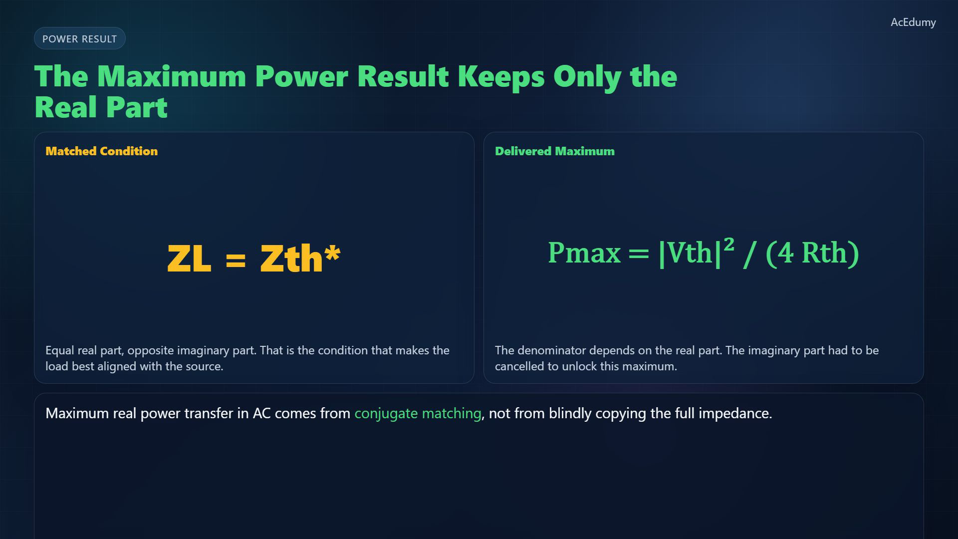
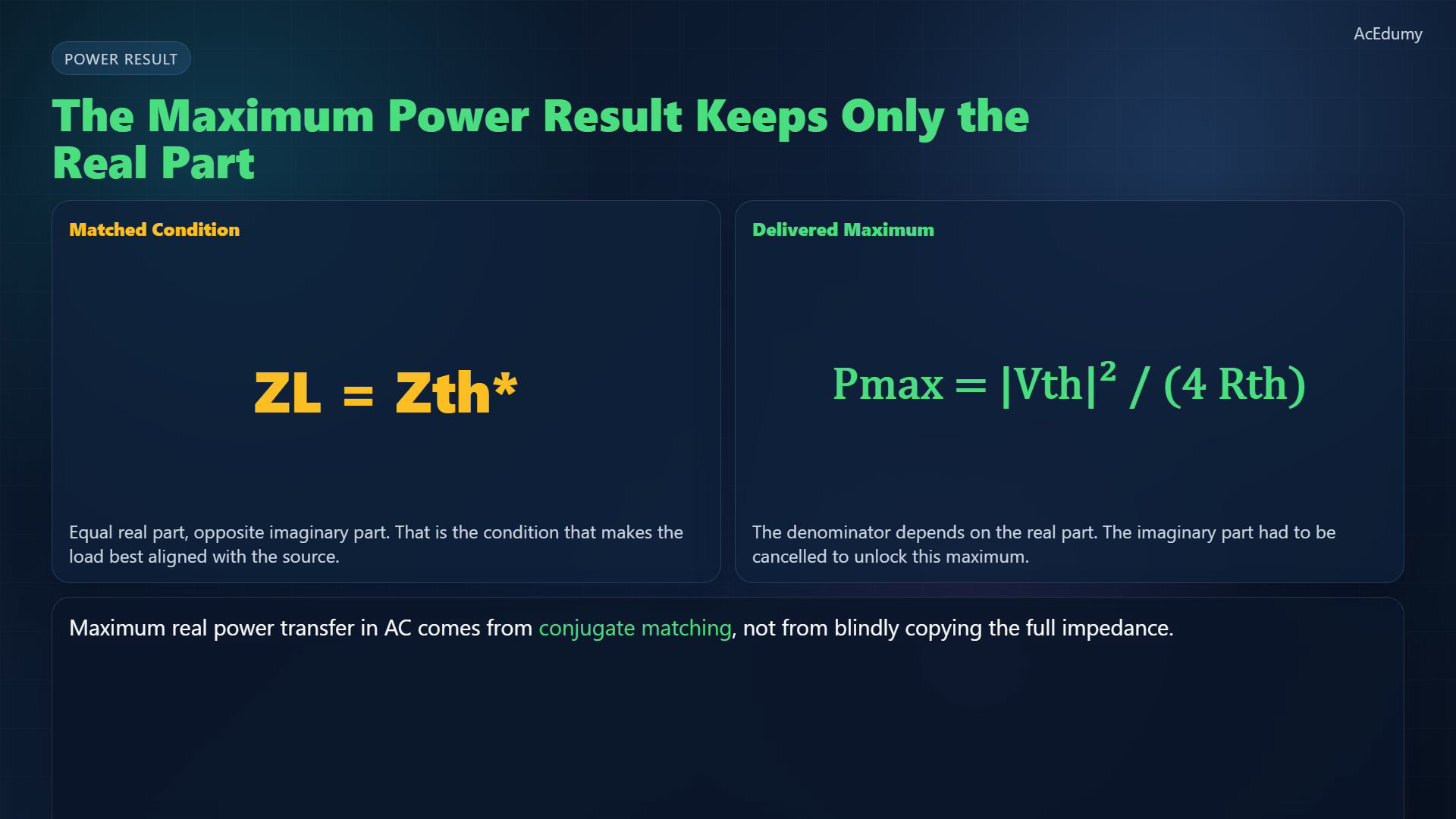
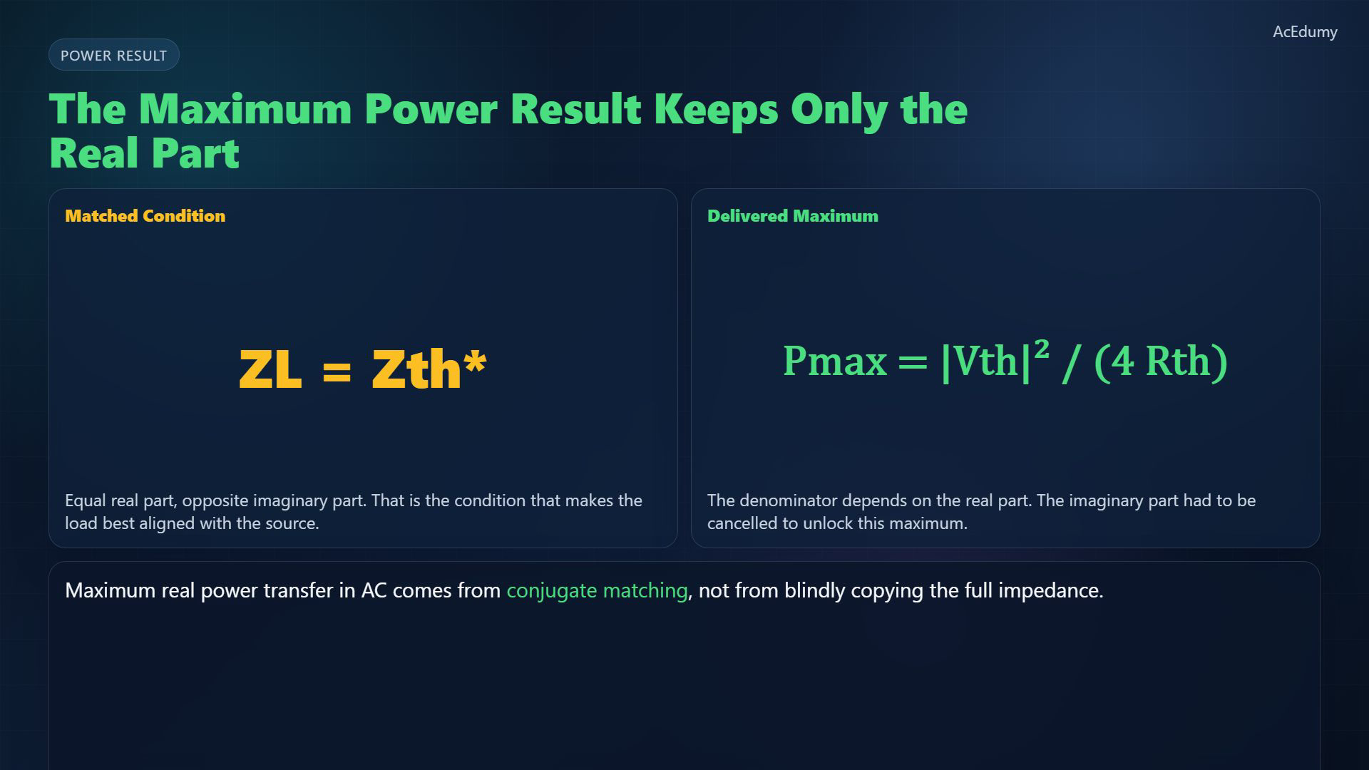
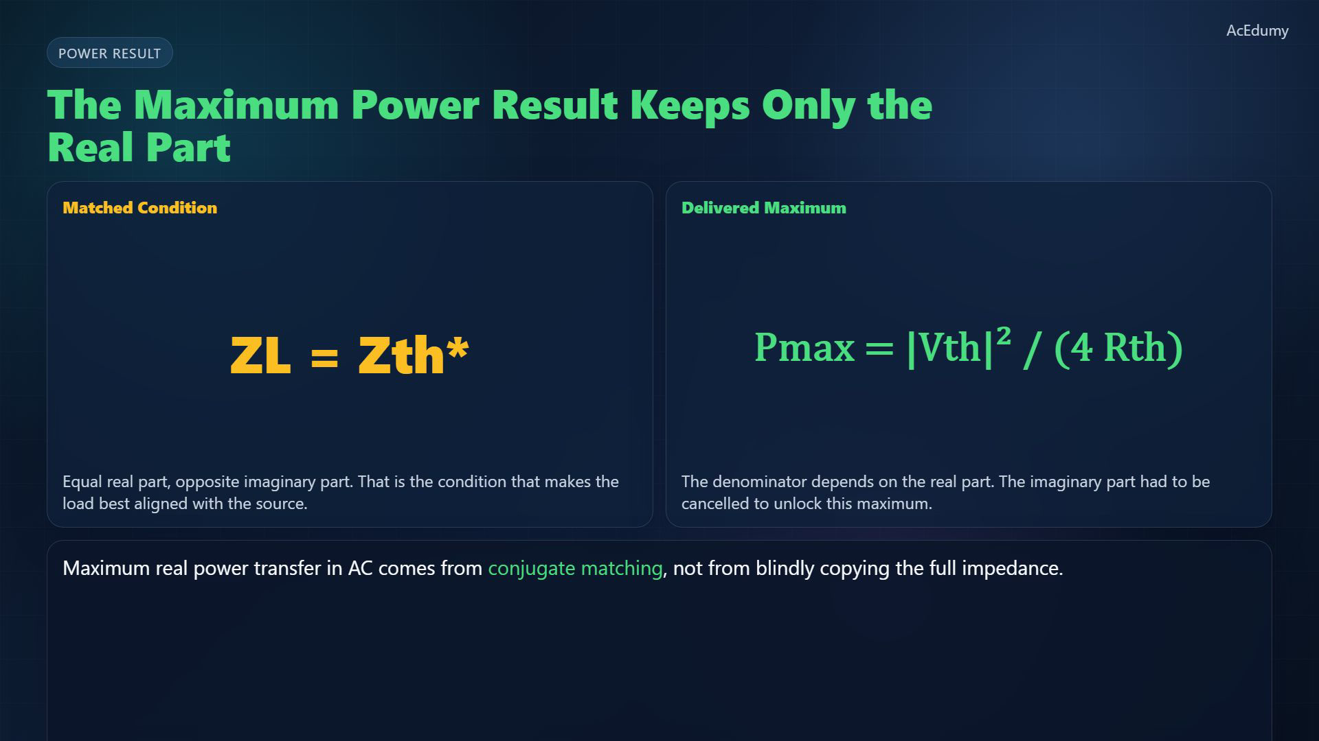
Original-video reference card, not a newly corrected circuit. Five problematic scenes use this lesson's bridge or maximum-power card. Formulas assume a fixed RMS Thevenin source with positive resistance and adjustable load; source narration remains unchanged and awaits teaching/publication QA. At conjugate match, with RMS source voltage and strictly positive source resistance:For this 4-ohm source, voltage in volts gives maximum load power in watts:In the ideal two-resistance Thevenin model, matched real powers are equal; this is not a maximum-efficiency claim:Narration transcript
Under the matched condition, the maximum real power delivered to the load becomes the magnitude of V Thevenin squared divided by four times R Thevenin. Notice what remains in the denominator: only the real part. That is why the reactive part must be cancelled instead of copied.
7. Keep the conjugate-matching conditions

Original-video reference card, not a newly corrected circuit. Five problematic scenes use this lesson's bridge or maximum-power card. Formulas assume a fixed RMS Thevenin source with positive resistance and adjustable load; source narration remains unchanged and awaits teaching/publication QA. Equal impedance agrees with conjugate matching only when the source reactance is zero.The unconstrained result requires independently adjustable load resistance and reactance:If only a purely resistive load can vary, its optimum instead is:The original ending mentions resonance. The next indexed lesson is Balanced Three-Phase Intuition.Narration transcript
So the AC rule is not equal impedance. It is conjugate matching. Keep the real parts equal, flip the sign of the imaginary part, and the load receives the maximum real power available from that source. Next, we move toward resonance and frequency-selective behavior.
Source video: Circuit Theory-2 #09 AC Maximum Power Transfer (2:35)