Circuit Theory 2 · AC source transformations, Thevenin and Norton equivalents
#05 Preserve a one-port voltage-current relation with explicit terminal references and equivalent impedance
Convert series-voltage and parallel-current source forms, verify the full terminal relation, and compute the same load response with Thevenin or Norton.
Question

Work with a linear time-invariant lumped AC network in sinusoidal steady state at one common frequency. Uppercase V and I denote phasors, with a consistent peak or root-mean-square (RMS) convention. Remove the external load before finding the equivalent. Define terminal voltage as a minus b, load current as leaving a and returning at b, voltage-source polarity as upper terminal positive, and Norton source current as flowing internally from b toward a. The original sine-source drawing leaves polarity unmarked; these are explicit notebook references. Derive source conversion for a finite nonzero impedance Z, preserving its value but changing its connection from series with the voltage source to parallel with the current source. Verify the complete terminal relation, open-circuit voltage and short-circuit current. Matching two zero source readings does not identify an impedance: use a test source or the complete port relation. Thevenin and Norton formulas require well-defined equivalents; ideal zero-impedance voltage sources, ideal infinite-impedance current sources and singular networks need separate treatment. To find equivalent impedance, remove the load, set only independent sources to zero (short ideal voltage sources, open ideal current sources), retain dependent sources, and use a nonzero test current into terminal a with voltage a minus b. Do not deactivate sources when finding the original open-circuit voltage or short-circuit current. Reconnect the same load between a and b. The load-current formula requires Z_TH+Z_L nonzero; the admittance formula also requires finite nonzero Z_L and a nonzero total admittance. Equivalent load-facing behavior does not assert identical internal branch currents or power. The source video and narration remain unchanged; their shorthand generalizations and legacy diagram/readability issues require manual publication QA.
Written solution and narration transcript(shows the full solution)
Below are all the lines written in the notebook together with the full narration transcript.
1. Preserve the behavior seen at the two terminals
Original-video reference, not a newly corrected diagram. For the two-terminal drawing, take voltage a minus b, the voltage source upper terminal positive and source current toward a; the load connects across a and b. Use the impedance domain for a linear time-invariant network in sinusoidal steady state at one common frequency.Source transformations, Thevenin and Norton describe the same two-terminal network, called a one-port.Keep the load-facing behavior, not necessarily the internal branch currents or power.Take voltage a minus b and load current leaving a. With the voltage source upper terminal positive, the terminal relation is:Narration transcript
Once we move into the impedance domain, some circuits can still look crowded. Source transforms, Thevenin, and Norton give us a cleaner one-port viewpoint. The goal is not to change the physics. The goal is to preserve the same terminal behavior while using a simpler equivalent form.
2. Change source form while keeping the same impedance
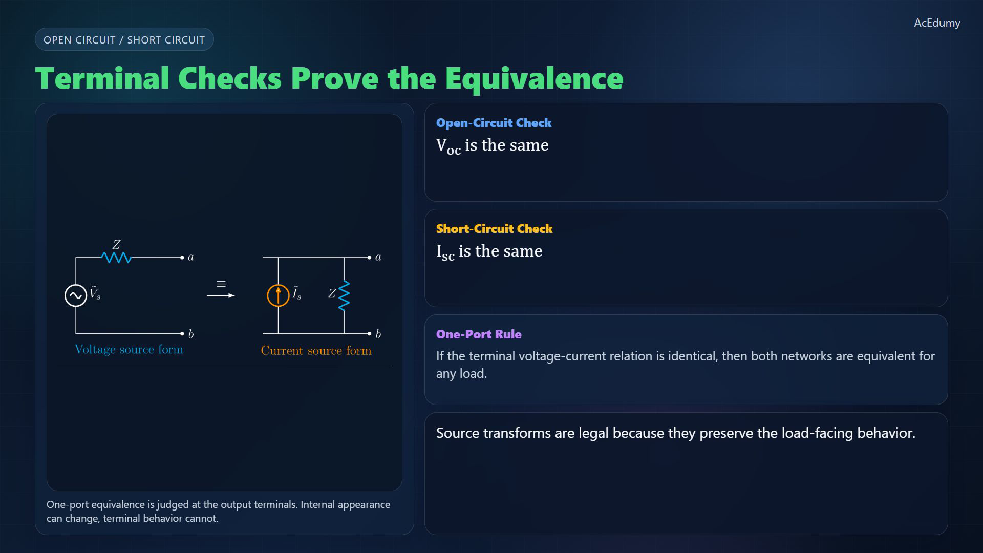
Original-video reference, not a newly corrected diagram. For the two-terminal drawing, take voltage a minus b, the voltage source upper terminal positive and source current toward a; the load connects across a and b. Alternating-current (AC) source conversion replaces the direct-current (DC) resistance by a finite, nonzero impedance.A voltage source with series Z converts to a current source with parallel Z. Source current points from b toward a:The impedance keeps its value, but its connection changes from series to parallel. The reverse source relation is:The parallel form gives the same load current by Kirchhoff's current law:Narration transcript
In A C, the source-transform rule is the same idea as in D C, except resistance becomes impedance. A voltage source V sub s in series with Z is equivalent to a current source I sub s in parallel with the same Z, where I sub s equals V sub s over Z. The impedance does not disappear and it does not change value. Only the source description changes.
3. Check the open circuit and short circuit
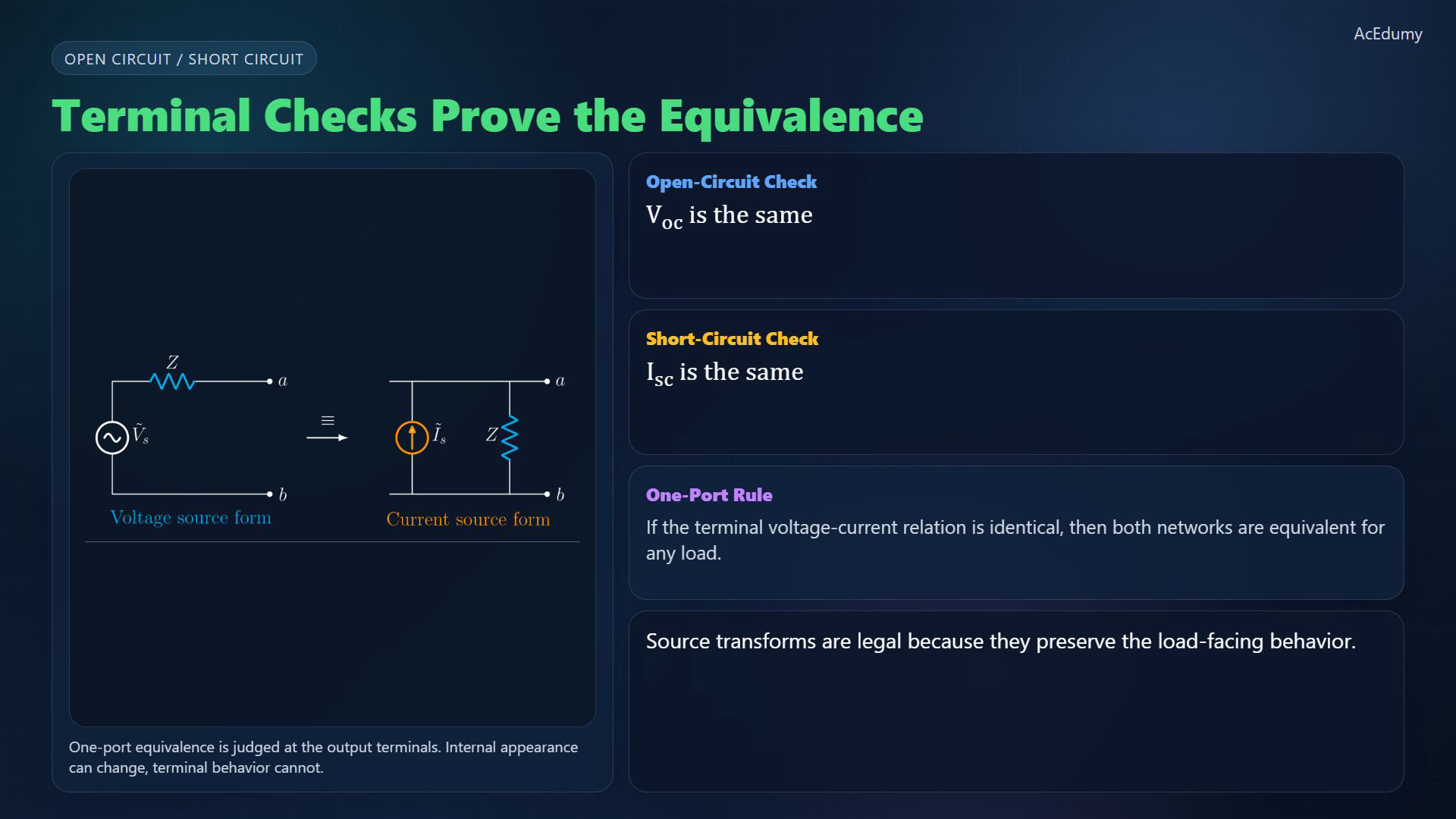
Original-video reference, not a newly corrected diagram. For the two-terminal drawing, take voltage a minus b, the voltage source upper terminal positive and source current toward a; the load connects across a and b. Check both forms at the same terminals and with the same sign references.After substituting the conversion relation, both forms obey the complete terminal equation:Open circuit — disconnect the external load. Load current is zero, so:Short circuit — connect a to b. Terminal voltage is zero; current through the short flows a to b:Matching open and short readings is not sufficient when both are zero. Compare the complete port relation or measure impedance with a test source.Narration transcript
Why is that legal? Because both forms produce the same terminal voltage and the same terminal current for any attached load. Open-circuit the output and you recover the same open-circuit voltage. Short-circuit the output and you recover the same short-circuit current. Matching those terminal conditions is the essence of one-port equivalence.
4. Find the Thevenin voltage and impedance
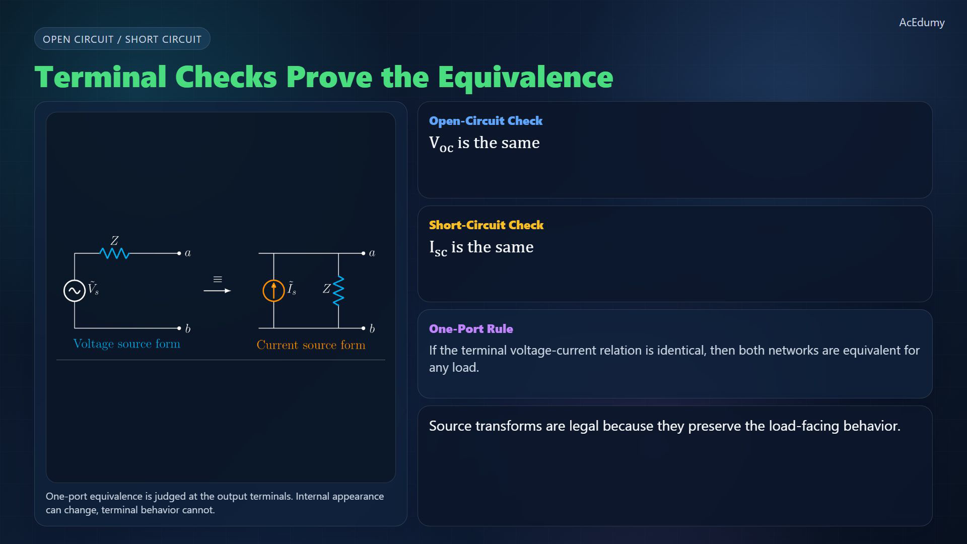
Original-video reference, not a newly corrected diagram. For the two-terminal drawing, take voltage a minus b, the voltage source upper terminal positive and source current toward a; the load connects across a and b. Thevenin is the voltage-source view. In the reference drawing, read the series source and Z as the equivalent, with the load outside it.A well-defined Thevenin equivalent contains one voltage source and one series impedance. Ideal-source or singular exceptions require separate treatment.Keep the original sources active and remove the load to find the open-circuit voltage. Impedance is found separately, as explained in the workflow:Narration transcript
This leads directly to Thevenin. Any linear A C network seen from two terminals can be replaced by one voltage source in series with one impedance. The Thevenin voltage is the open-circuit terminal voltage, and the Thevenin impedance is the equivalent impedance seen from the same terminals.
5. Relate Norton to the same Thevenin equivalent
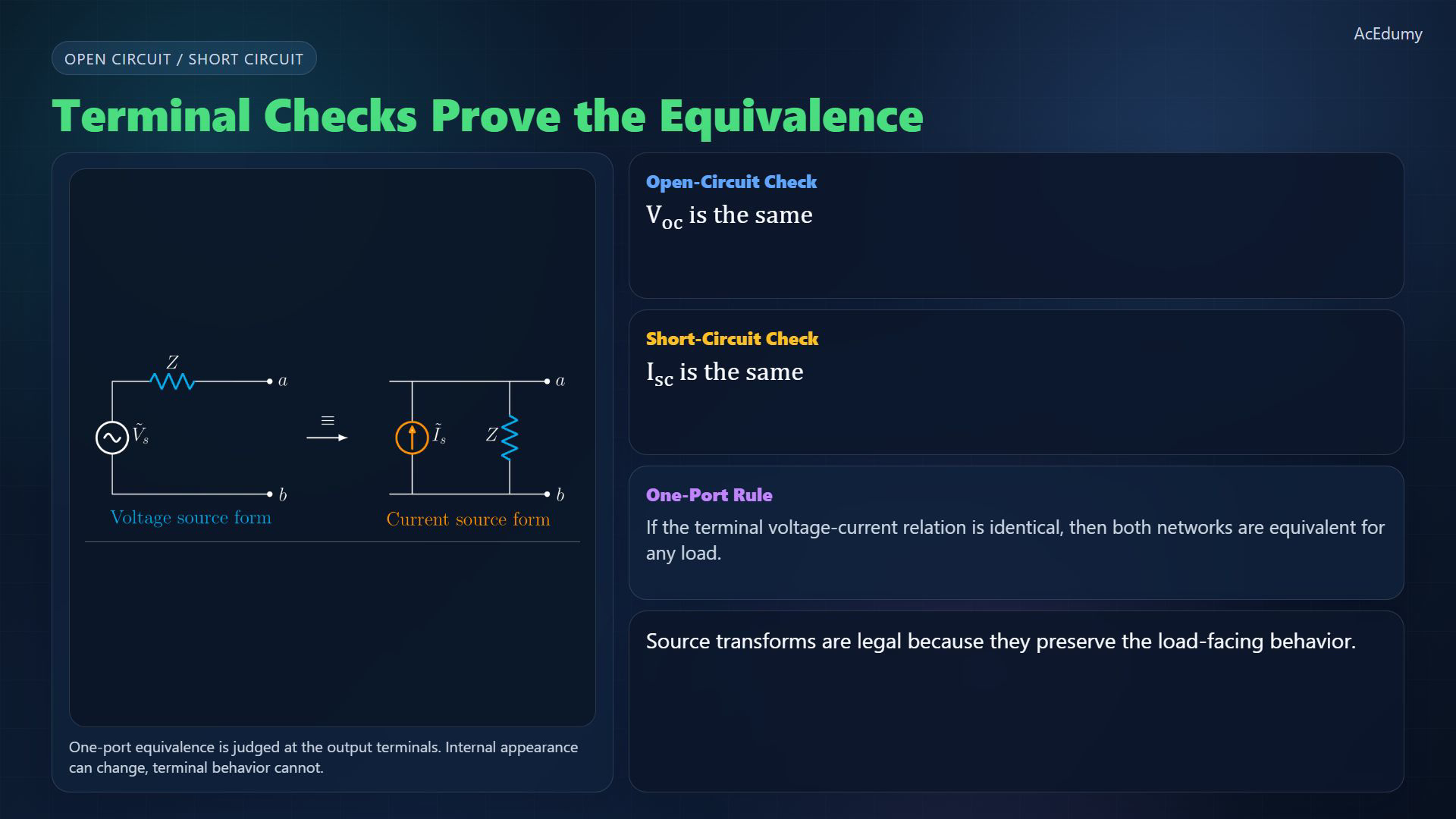
Original-video reference, not a newly corrected diagram. For the two-terminal drawing, take voltage a minus b, the voltage source upper terminal positive and source current toward a; the load connects across a and b. Norton is the current-source view of the same one-port; its internal source arrow points from b toward a.The source is parallel with the equivalent impedance; both share the load terminals:Keep the original sources active for the short-circuit calculation. With external short current from a to b:For a finite nonzero equivalent impedance, the two source values are related by:Narration transcript
The Norton form is the current-source view of the same one-port. The same linear A C network can also be written as a current source in parallel with the same impedance. The Norton current is the short-circuit current, and the Norton impedance equals the Thevenin impedance. The two views are connected by I sub N equals V sub T H over Z sub T H.
6. Choose terminals, find the equivalent, then attach the load
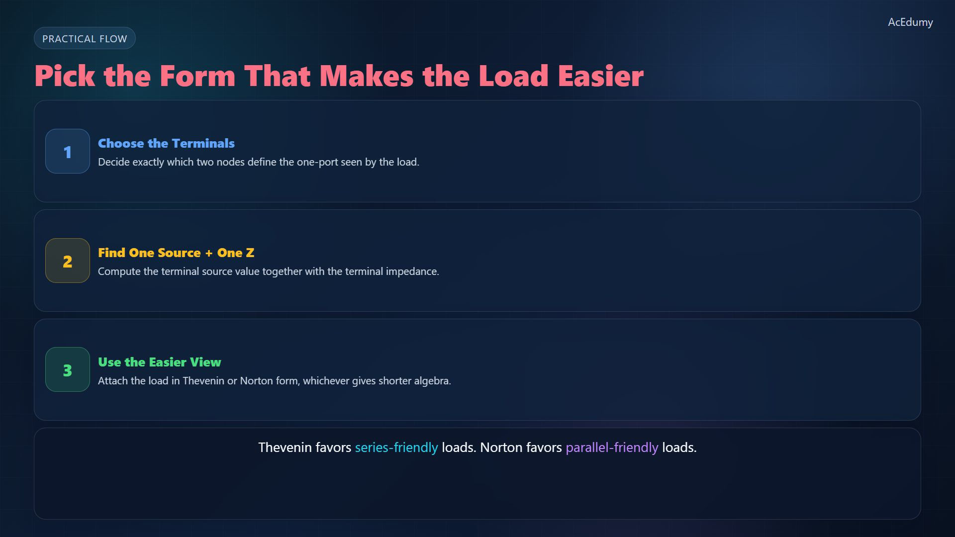
Original-video reference, not a newly corrected diagram. For the two-terminal drawing, take voltage a minus b, the voltage source upper terminal positive and source current toward a; the load connects across a and b. Choose terminals, find the unloaded equivalent, then reconnect the load.First choose a and b, disconnect the external load, and keep the same voltage and current references throughout.For impedance only, zero independent sources, retain dependent sources and apply a test current into a. Short ideal voltage sources and open ideal current sources:Reconnect the load between a and b. For a nonzero total series impedance, Thevenin gives:Norton may make parallel algebra easier. For finite nonzero impedances and a nonzero total admittance, the same load voltage is:Narration transcript
So the workflow is short. First, choose the output terminals. Second, find the Thevenin or Norton source together with the terminal impedance. Third, connect the load to whichever form makes the algebra easier. Series-friendly loads often look cleaner in Thevenin form, while parallel-friendly loads often look cleaner in Norton form.
7. Keep the same terminal behavior
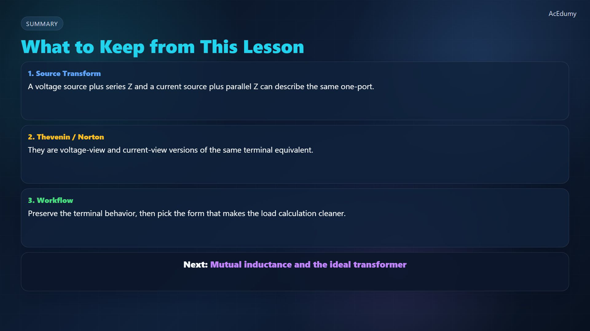
Original-video reference, not a newly corrected diagram. For the two-terminal drawing, take voltage a minus b, the voltage source upper terminal positive and source current toward a; the load connects across a and b. Source transformations, Thevenin and Norton are related one-port descriptions, under the stated model and existence conditions.Use consistent phasor voltage, current and frequency references; do not mix peak and RMS values.Preserving the complete terminal relation preserves the response of the same admissible load, not the internal power distribution.Next: mutual inductance and the ideal transformer.Narration transcript
Source transforms, Thevenin, and Norton are not separate tricks. They are three ways of describing the same A C one-port. Once the terminal behavior is preserved, the load sees no difference. In the next lesson, we move to mutual inductance and the ideal transformer.
Source video: Circuit Theory-2 #05 AC Source Transforms, Thevenin, and Norton (2:51)