Antenna Theory · Antenna Arrays, Array Factor, and Pattern Multiplication
#11 Path and feed phase in a two-element array, the array factor, pattern multiplication, electronic beam steering, and broadside/endfire conditions
Turn path and feed phase for two sources into an array factor that steers the combined beam electronically.
Question

Derive the total phase difference and array factor for two identical antennas separated along z; multiply by the element pattern and explain broadside-to-endfire steering through β.
Written solution and narration transcript(shows the full solution)
Below are all the lines written in the notebook together with the full narration transcript.
1. See the new freedom provided by multiple antenna elements
Geometric path phase and feed phase set the array factor; multiplying it by the element pattern produces the steered total beam. Every antenna we have studied so far is a single element.A single dipole radiates in a fixed doughnut-shaped pattern.You cannot change where the energy goes without physically rotating the wire.An antenna array solves this by placing several identical elements in a row and feeding them with controlled phase shifts.The spacing and phasing between elements create a new degree of freedom that lets the combined beam point in any desired direction, without moving any part of the hardware.Narration transcript
Every antenna we have studied so far is a single element. A single dipole radiates in a fixed doughnut-shaped pattern. You cannot change where the energy goes without physically rotating the wire. An antenna array solves this by placing several identical elements in a row and feeding them with controlled phase shifts. The spacing and phasing between elements create a new degree of freedom that lets the combined beam point in any desired direction, without moving any part of the hardware.
2. Set up path and feed phase for a two-element array

Geometric path phase and feed phase set the array factor; multiplying it by the element pattern produces the steered total beam. Start with the simplest array: two identical sources separated by a distance d along the z axis.Both radiate the same element pattern, but the signal from each one travels a slightly different path to reach a far-field observer.The path difference depends on the angle θ and the spacing d.If we also add a deliberate phase shift β between the two feeds, the total field at the observer is the sum of two phasors, one from each element, offset by both the geometric path difference and the intentional feed phase.Narration transcript
Start with the simplest array: two identical sources separated by a distance d along the z axis. Both radiate the same element pattern, but the signal from each one travels a slightly different path to reach a far-field observer. The path difference depends on the angle theta and the spacing d. If we also add a deliberate phase shift beta between the two feeds, the total field at the observer is the sum of two phasors, one from each element, offset by both the geometric path difference and the intentional feed phase.
3. Derive the AF=2cos(ψ/2) array factor
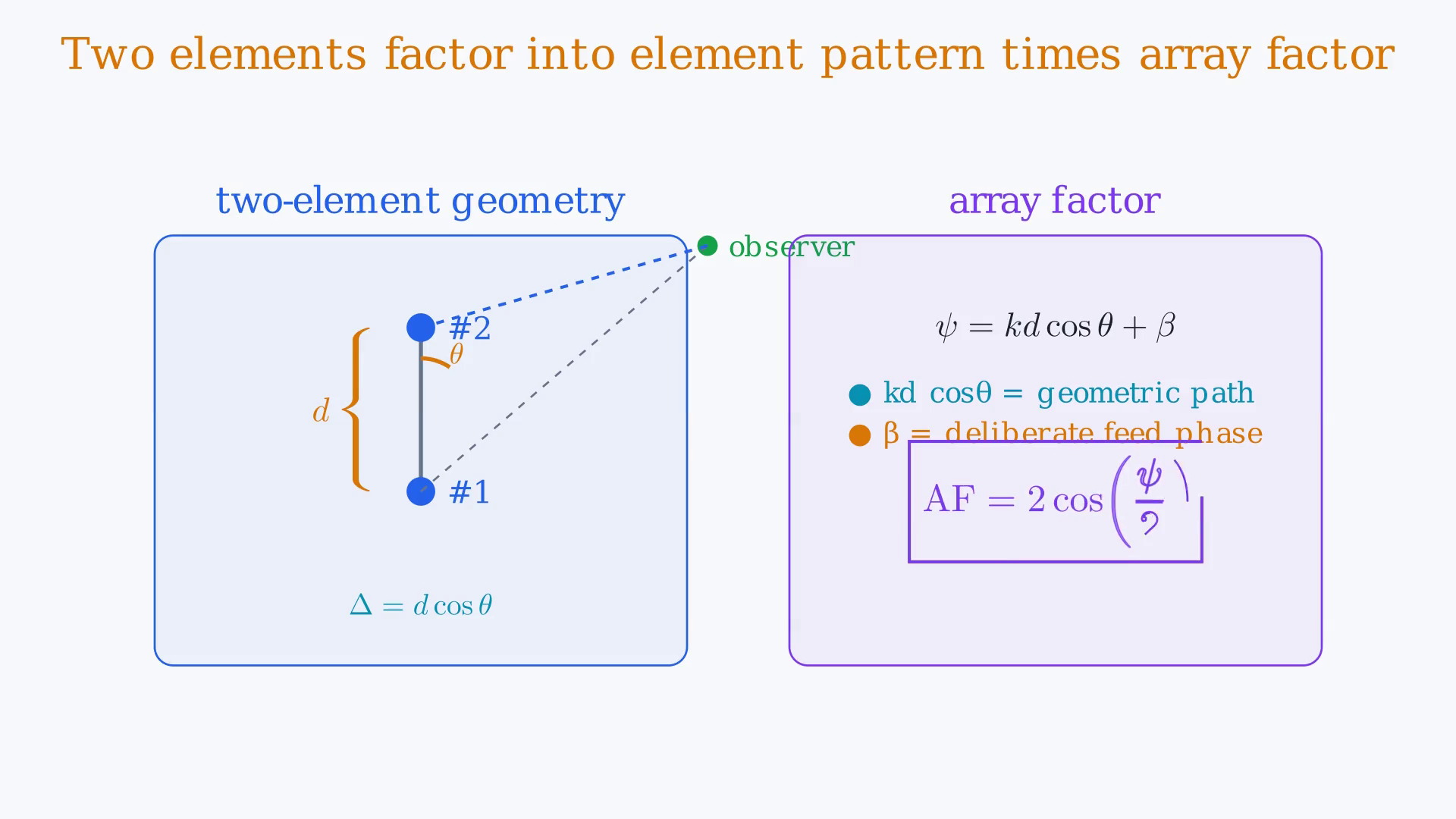
Geometric path phase and feed phase set the array factor; multiplying it by the element pattern produces the steered total beam. When we write out that two-phasor sum, a remarkable factorization appears.The total field splits into the element pattern, which is the radiation of one element alone, times a new multiplier called the array factor.For two elements the array factor is simply 2cos(ψ/2).The total phase difference ψ = kd cosθ + β, where kd cosθ is the geometric part and β is the feed offset.This factorization is the pattern multiplication principle: total pattern equals element pattern times array factor.Narration transcript
When we write out that two-phasor sum, a remarkable factorization appears. The total field splits into the element pattern, which is the radiation of one element alone, times a new multiplier called the array factor. For two elements the array factor is simply two cosine of half the total phase difference. The total phase difference psi equals k d cosine theta plus beta, where k d cosine theta is the geometric part and beta is the feed offset. This factorization is the pattern multiplication principle: total pattern equals element pattern times array factor.
4. Build total pattern as element pattern × array factor
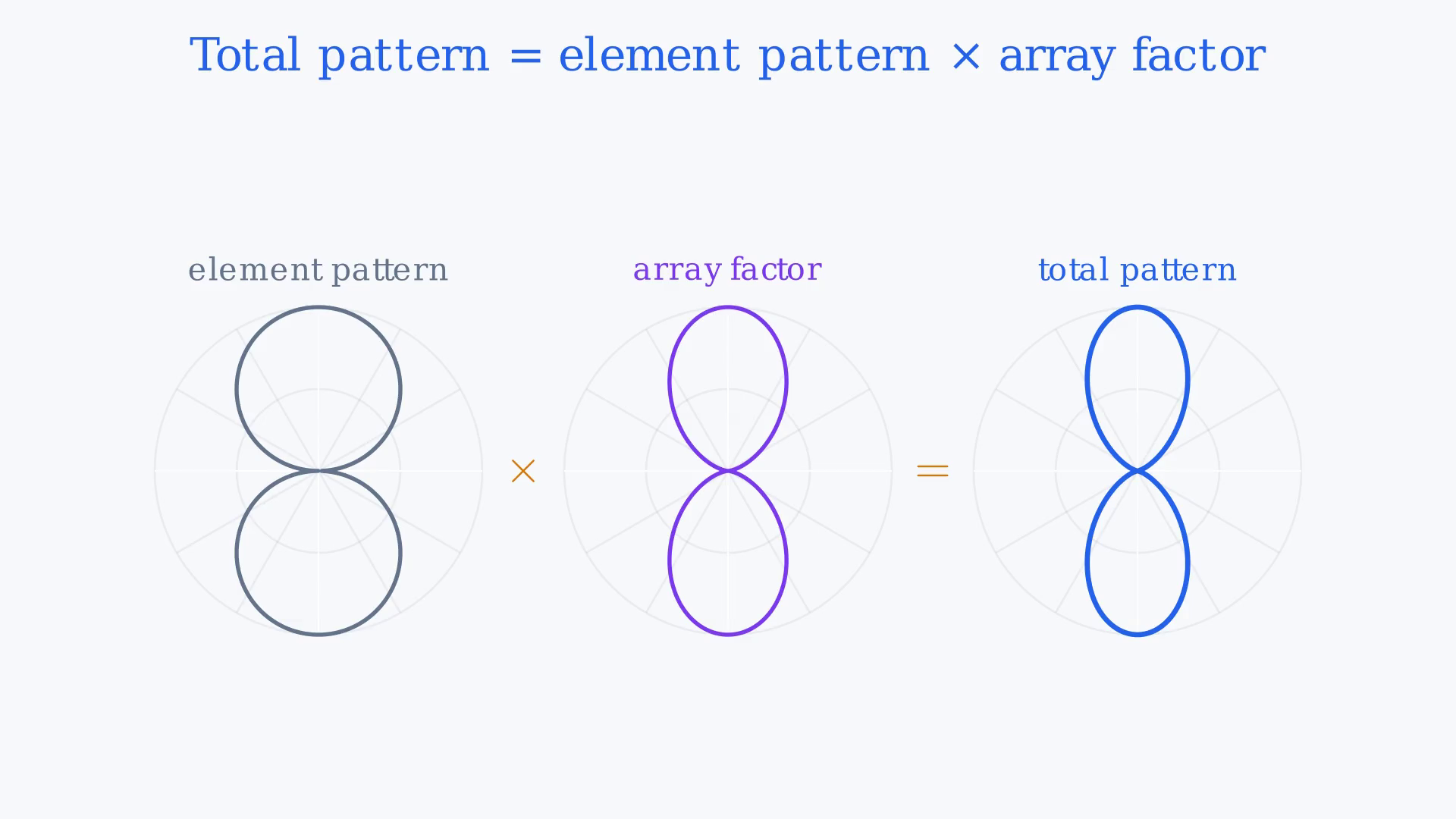
Geometric path phase and feed phase set the array factor; multiplying it by the element pattern produces the steered total beam. Pattern multiplication means you can design the element and the array independently.The element pattern sets the envelope, the broad shape that each antenna would produce alone.The array factor then carves narrower lobes inside that envelope.If the element has a broadside null, no array factor can create a beam there.If the array factor has a null, the total pattern also has a null, even if the element pattern is strong in that direction.The final pattern is the product of both, taken at every angle.Narration transcript
Pattern multiplication means you can design the element and the array independently. The element pattern sets the envelope, the broad shape that each antenna would produce alone. The array factor then carves narrower lobes inside that envelope. If the element has a broadside null, no array factor can create a beam there. If the array factor has a null, the total pattern also has a null, even if the element pattern is strong in that direction. The final pattern is the product of both, taken at every angle.
5. Steer the beam electronically by changing β
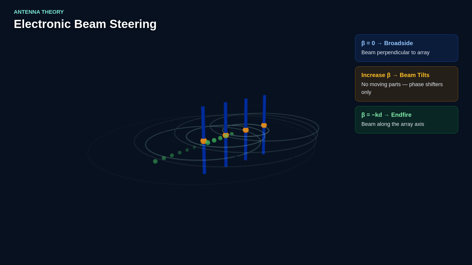
Geometric path phase and feed phase set the array factor; multiplying it by the element pattern produces the steered total beam. The power of this factorization is beam steering.When β=0, both elements radiate in phase and the array factor peaks at broadside.As you increase β, the peak of the array factor swings away from broadside.The beam tilts toward endfire without moving any hardware.This is exactly how phased array radars and modern 5G base stations work: electronic phase shifters replace mechanical rotation, letting the beam scan across angles in microseconds.Narration transcript
The power of this factorization is beam steering. When beta equals zero, both elements radiate in phase and the array factor peaks at broadside. As you increase beta, the peak of the array factor swings away from broadside. The beam tilts toward endfire without moving any hardware. This is exactly how phased array radars and modern 5G base stations work: electronic phase shifters replace mechanical rotation, letting the beam scan across angles in microseconds.
6. Compare broadside and endfire phase conditions
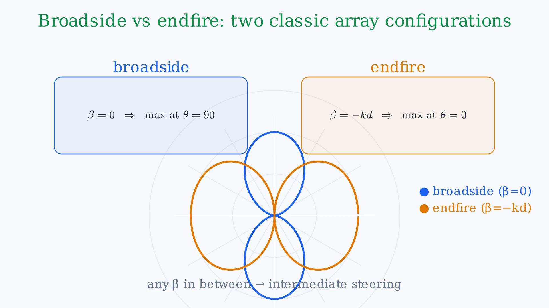
Geometric path phase and feed phase set the array factor; multiplying it by the element pattern produces the steered total beam. Two classic configurations deserve their own names.The broadside array uses β=0, so the maximum radiation is perpendicular to the array axis.This is the natural choice when you want to illuminate a wide area in front of the antenna.The endfire array uses β=−kd, which shifts the maximum along the array axis, straight ahead.Endfire is useful when you need a narrow beam in one forward direction.Every other steering angle is simply a value of β between these two extremes.Narration transcript
Two classic configurations deserve their own names. The broadside array uses beta equals zero, so the maximum radiation is perpendicular to the array axis. This is the natural choice when you want to illuminate a wide area in front of the antenna. The endfire array uses beta equals minus k d, which shifts the maximum along the array axis, straight ahead. Endfire is useful when you need a narrow beam in one forward direction. Every other steering angle is simply a value of beta between these two extremes.
7. Summarize the three key ideas of antenna arrays
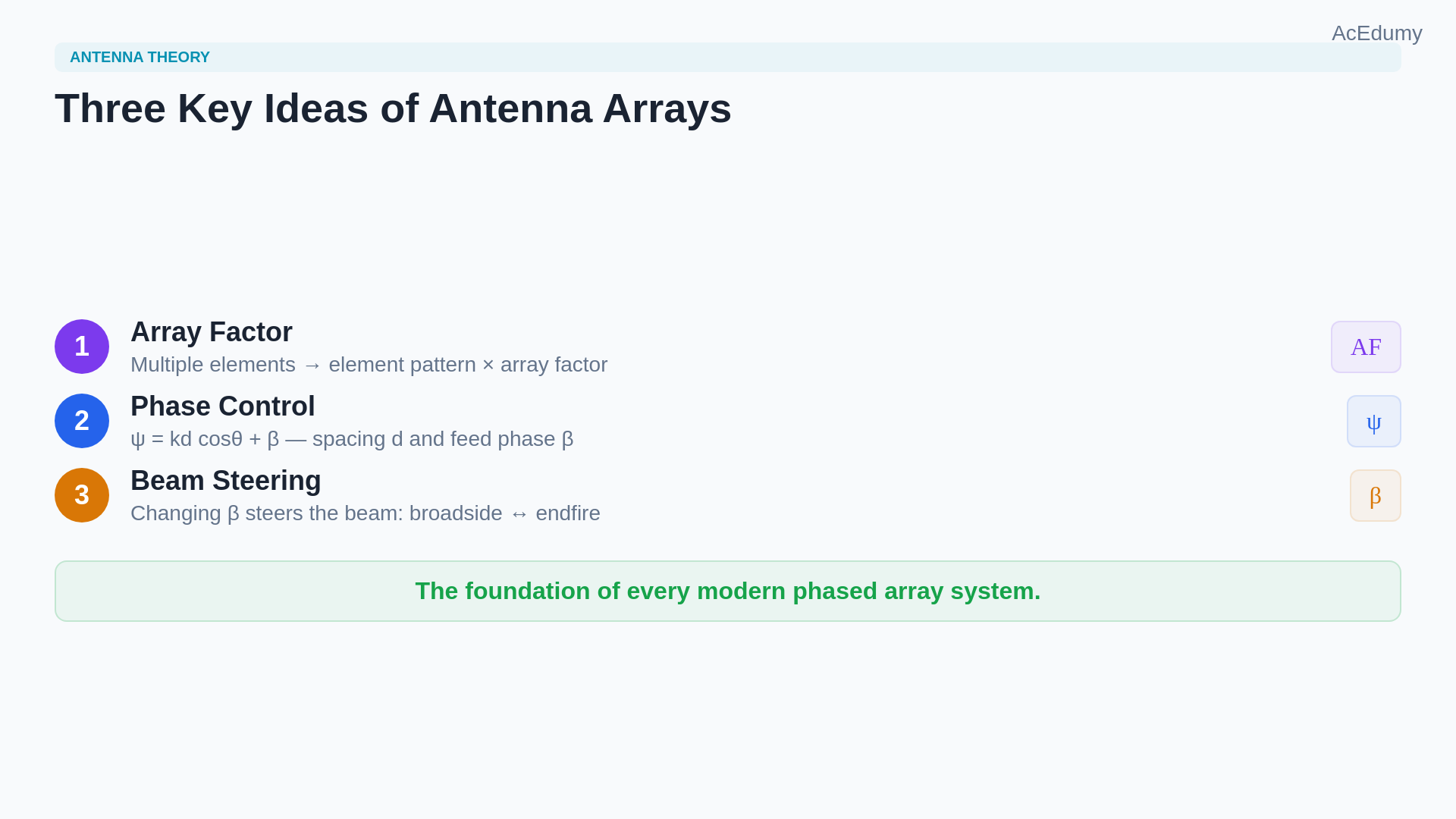
Geometric path phase and feed phase set the array factor; multiplying it by the element pattern produces the steered total beam. Antenna arrays introduce three key ideas.First, multiple elements create an array factor that multiplies the element pattern.Second, the array factor depends on the spacing d and the phase shift β between feeds.Third, changing β steers the beam electronically, from broadside through any intermediate angle to endfire.This is the foundation of every modern phased array system.Narration transcript
Antenna arrays introduce three key ideas. First, multiple elements create an array factor that multiplies the element pattern. Second, the array factor depends on the spacing d and the phase shift beta between feeds. Third, changing beta steers the beam electronically, from broadside through any intermediate angle to endfire. This is the foundation of every modern phased array system.
8. Prepare to generalize from two to N elements
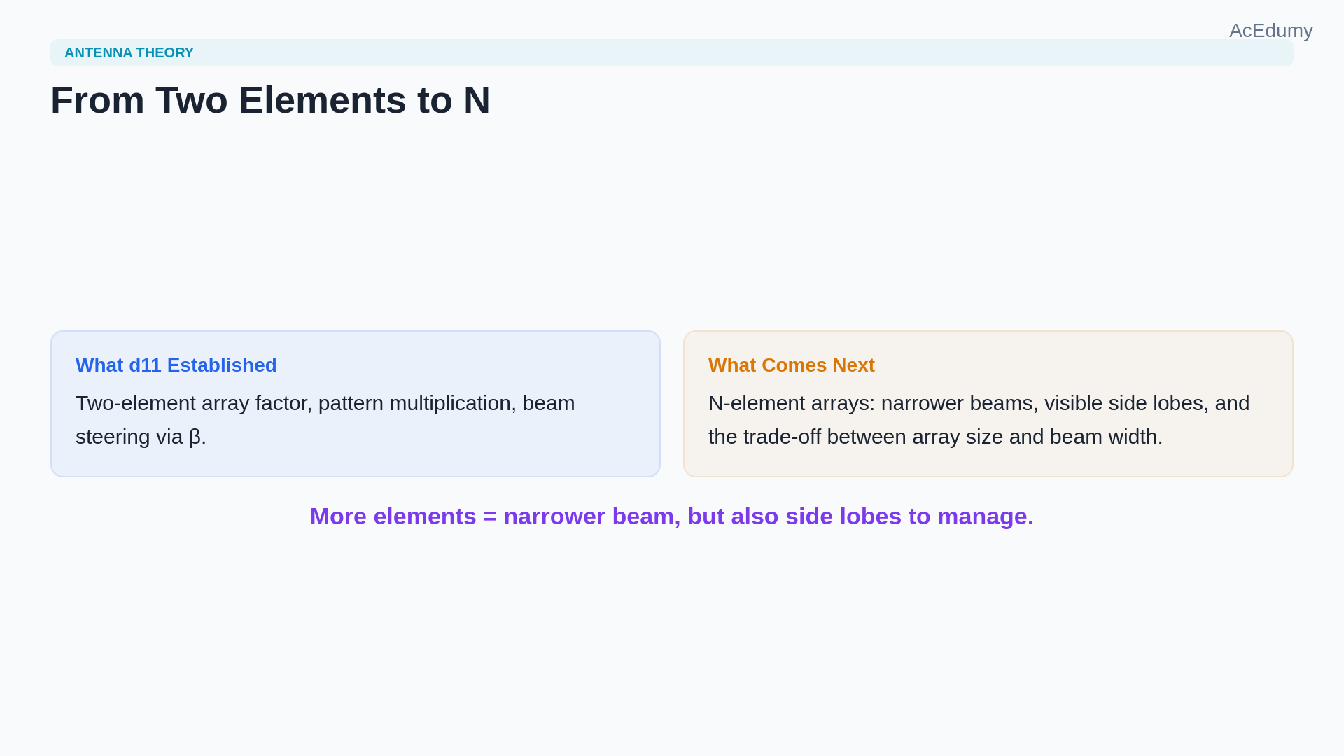
Geometric path phase and feed phase set the array factor; multiplying it by the element pattern produces the steered total beam. We derived the array factor for two elements, but real systems use tens or hundreds.Extending the same logic to N elements will reveal how the beam narrows as the array grows, and how side lobes appear.That N-element generalization is the next step.Narration transcript
We derived the array factor for two elements, but real systems use tens or hundreds. Extending the same logic to N elements will reveal how the beam narrows as the array grows, and how side lobes appear. That N-element generalization is the next step.
Source video: Antenna Theory #11 | Antenna Arrays & Array Factor | Pattern Multiplication (4:49)