Circuit Theory 2 · Balanced three-phase intuition
#10 Relate equal sinusoids, a fixed phase sequence and zero-sum geometry
Build the balanced three-phase picture from equal sinusoids, an explicit ABC reference and zero-sum geometry, with load conditions kept separate.
Question
Consider an ideal balanced sinusoidal set of phase-to-common-neutral voltages a, b and c at one positive angular frequency omega. Every phase has the same nonzero peak V_m and RMS magnitude V_rms=V_m/sqrt(2). Use ABC positive sequence and a sine reference: v_a(t)=V_m sin(omega t), v_b(t)=V_m sin(omega t-120 degrees), v_c(t)=V_m sin(omega t+120 degrees). The common horizontal variable in the original waveform figure is omega t in radians, not seconds; its unlabelled vertical scale is normalized voltage v/V_m, not a stated voltage rating. For this explicitly chosen sine convention the fixed complex RMS phasors are V_a=V_rms angle 0 degrees, V_b=V_rms angle -120 degrees and V_c=V_rms angle +120 degrees. Recover v_k(t) as sqrt(2) times the imaginary part of V_k exp(j omega t). A cosine-reference representation of the same waveforms shifts all three phasor angles by -90 degrees. Fixed phasors do not rotate; the original animation illustrates the common exp(j omega t) rotation with an arbitrary common offset. Its reference formulas are not the instantaneous arrow angles. Relative spacing and sequence stay unchanged. Translate vectors head to tail without rotating or reversing them: A points right, B down-left and C up-left for the stated fixed reference. The original triangle reverses the B/C ordering relative to the phasor scene, so the notebook uses this final's reviewed common-origin phasor card instead and states that it is not a head-to-tail triangle. Both the complex phasor sum and the instantaneous voltage sum are zero for this ideal balanced set. Zero sum alone does not prove equal magnitudes or 120-degree balance. Phase voltages are not line-to-line voltages: V_ab=V_a-V_b, with the a-to-b voltage reference. With ideal balanced sinusoidal load currents of equal RMS magnitude I_rms and the same phase lag phi relative to their corresponding phase voltages, total instantaneous real power is the constant 3 V_rms I_rms cos(phi). Individual phase powers generally pulsate. Balanced source voltages alone do not guarantee this result or zero neutral current under unbalanced or nonlinear loads. In an ideal balanced sinusoidal wye load, KCL makes the neutral current zero; without the current-balance condition it need not be zero. Triplen harmonics and machine winding geometry are outside the sinusoidal-set proof. Rotating-field intuition also needs the appropriate spatially displaced windings, not merely a drawing of three electrical phasors. Do not interpret this ideal circuit model as wiring instructions. Original audio/video remain unchanged; source raster layout, reference ambiguity and the broad smooth-behavior narration remain manual teaching/publication QA notes. This is an unpublished draft.
Written solution and narration transcript(shows the full solution)
Below are all the lines written in the notebook together with the full narration transcript.
1. Start with a symmetric three-phase set
Existing-video still, not a newly rendered animation. The zero-sum step reuses the common-origin phasor card, not the source triangle with reversed B/C ordering. Fixed sine-reference RMS phasors and rotating-vector illustrations are distinguished in the text; waveform axes represent normalized voltage versus electrical angle. Start with a balanced alternating-current (AC) set of three phase-to-neutral voltages, measured relative to the same reference.This lesson assumes a balanced sinusoidal set; arbitrary three-phase systems need not be balanced.Equal peak voltage, equal positive frequency and fixed 120° spacing define the balanced set.Keep voltage balance separate from load-current balance; later power and neutral-current results need their own conditions.Narration transcript
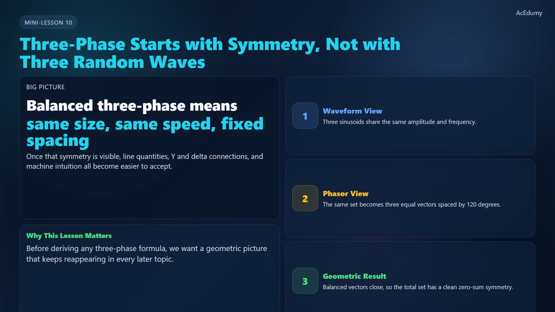
After single-phase AC ideas are in place, the next big jump is three-phase intuition. Three-phase systems do not start from three unrelated voltages. They start from a symmetric set: same magnitude, same frequency, and fixed spacing. That symmetry is the whole reason three-phase power becomes so useful.
2. Compare the three time-domain waves
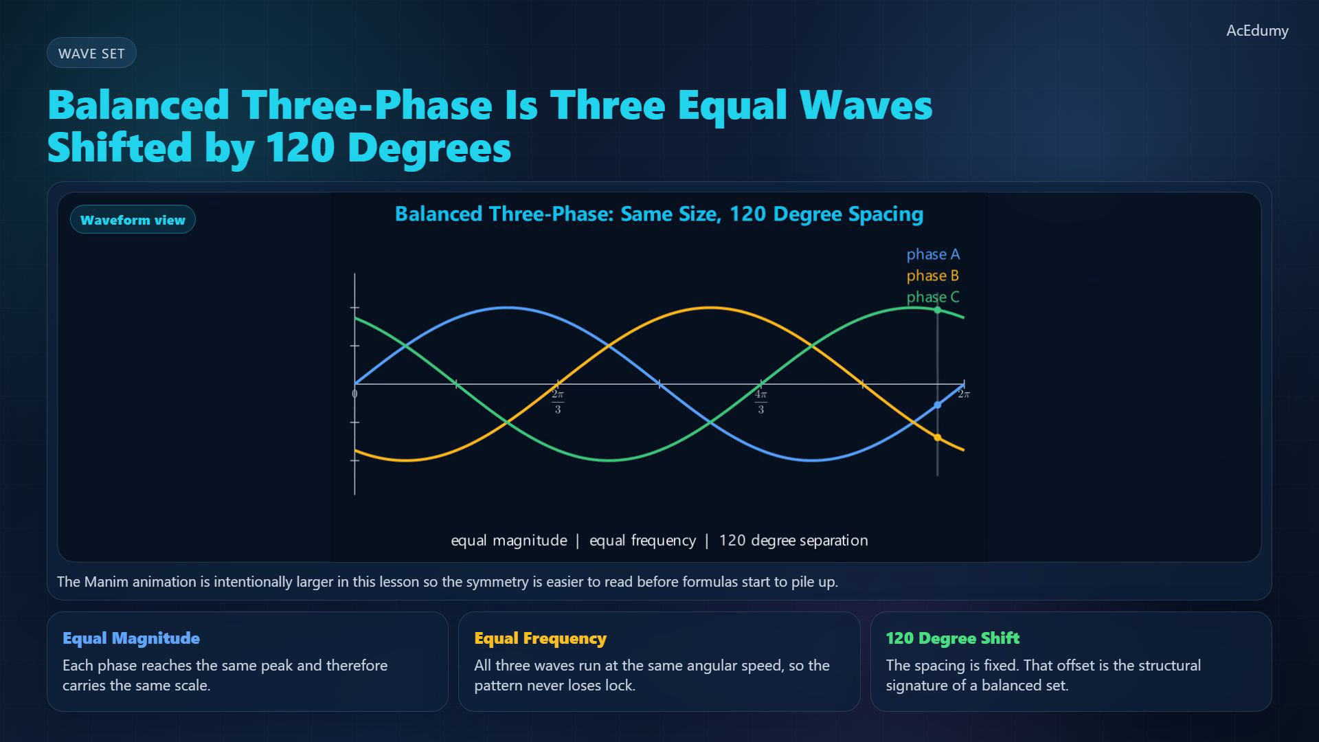
Existing-video still, not a newly rendered animation. The zero-sum step reuses the common-origin phasor card, not the source triangle with reversed B/C ordering. Fixed sine-reference RMS phasors and rotating-vector illustrations are distinguished in the text; waveform axes represent normalized voltage versus electrical angle. Let V_m be the common peak voltage and ω the angular frequency; use a sine reference:For ABC sequence, phase B lags phase A by 120°:Phase C leads A by 120°, equivalently lags B by 120° around the cycle:The horizontal axis is electrical angle ωt in radians; 120° is one third of the period:Narration transcript
In a balanced three-phase set, phase A, phase B, and phase C are sinusoidal waveforms of equal amplitude and equal frequency. What separates them is phase shift. Each waveform is displaced by one hundred twenty degrees from the next. So the three waves are different in time, but perfectly organized in structure.
3. Fix the phase sequence and reference
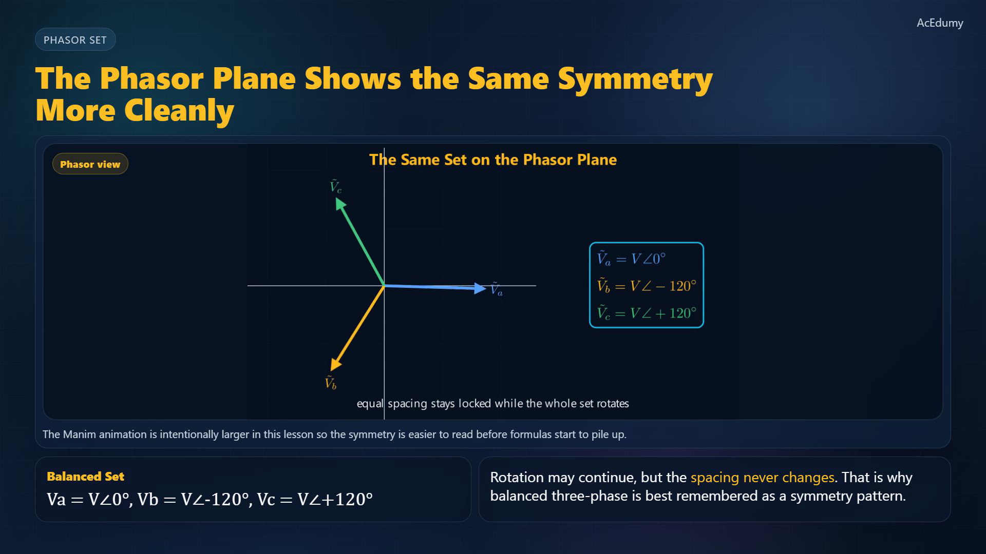
Existing-video still, not a newly rendered animation. The zero-sum step reuses the common-origin phasor card, not the source triangle with reversed B/C ordering. Fixed sine-reference RMS phasors and rotating-vector illustrations are distinguished in the text; waveform axes represent normalized voltage versus electrical angle. Choose phase A as the fixed sine-reference RMS phasor:For that same ABC reference, keep the signs consistent:The fixed phasors do not rotate. The animation illustrates a common time rotation; its fixed-reference formulas are not instantaneous arrow angles.Use the imaginary projection for this sine convention. A cosine convention shifts all three fixed angles by −90° without changing their spacing.Narration transcript
The same idea becomes even cleaner in phasor form. Balanced phase voltages become three equal vectors spaced by one hundred twenty degrees on the complex plane. As they rotate, that spacing stays locked. So balanced three-phase is really a symmetry pattern, not a pile of separate equations.
4. Add phase vectors without rotating them
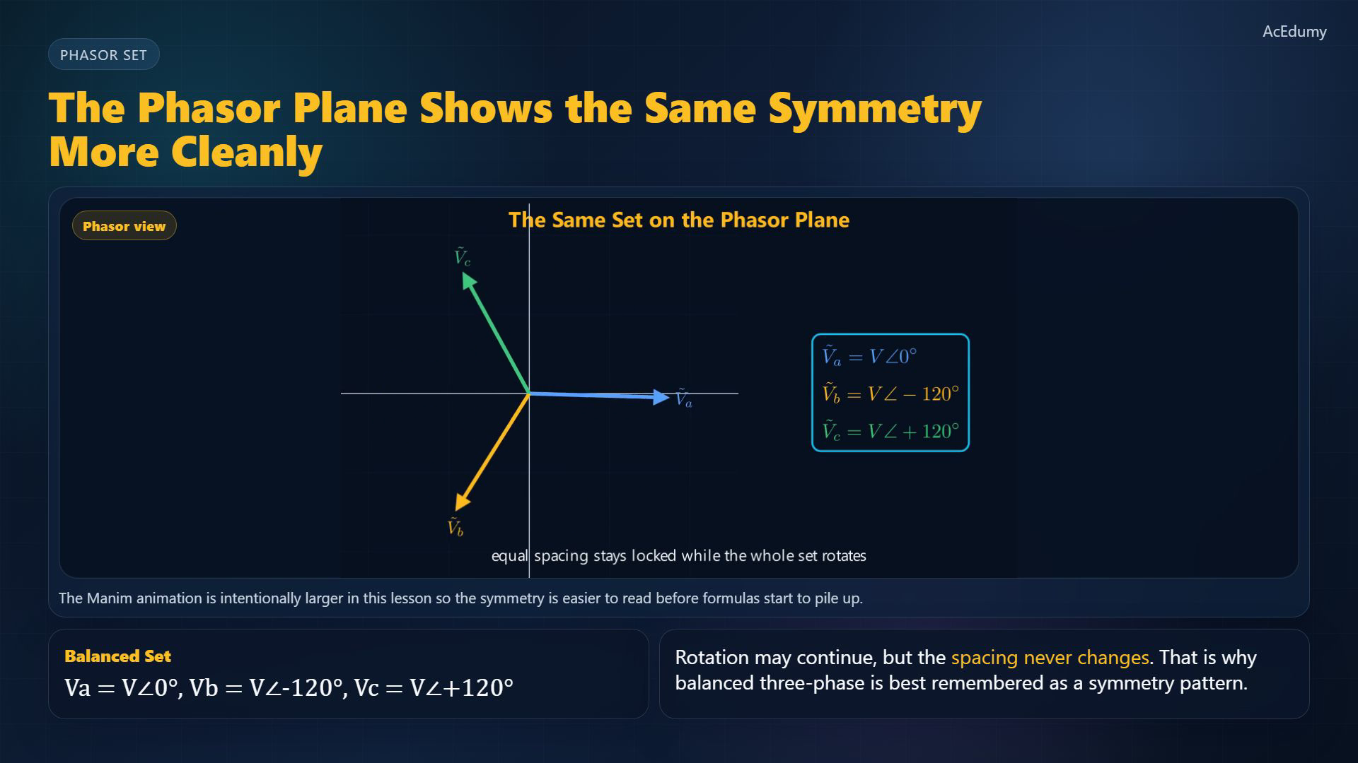
Existing-video still, not a newly rendered animation. The zero-sum step reuses the common-origin phasor card, not the source triangle with reversed B/C ordering. Fixed sine-reference RMS phasors and rotating-vector illustrations are distinguished in the text; waveform axes represent normalized voltage versus electrical angle. The reference still shows common-origin phasors, not a triangle. For the fixed ABC reference, A points right, B down-left and C up-left.Translate each vector head to tail without rotating or reversing its arrow; the third returns to the starting point.For the balanced phase-to-neutral RMS phasors:Their instantaneous voltages also cancel; this does not by itself prove zero load-neutral current:Narration transcript
Now look at the geometry of the balanced set. If you place the three phase vectors head to tail, they close into a triangle. That means their vector sum is zero. This simple geometric fact sits underneath many of the clean identities used in three-phase analysis.
5. Explain the conditions behind smooth total power

Existing-video still, not a newly rendered animation. The zero-sum step reuses the common-origin phasor card, not the source triangle with reversed B/C ordering. Fixed sine-reference RMS phasors and rotating-vector illustrations are distinguished in the text; waveform axes represent normalized voltage versus electrical angle. With balanced sinusoidal currents and equal phase lag φ, total instantaneous real power is constant:Line voltage from a to b is a difference, not a phase voltage; Y/Δ and machine geometry add their own conditions:Balanced sinusoidal load currents give zero neutral current in the ideal wye model. Balanced voltages alone do not guarantee this; other loads need a separate check.Narration transcript
This symmetry matters because it creates smooth total behavior. It also prepares the way for line-to-line relations, star and delta connections, and rotating-field intuition in machines. Before any formulas get heavy, the visual picture should already feel natural: three equal phases, equally spaced, working as one set.
6. Keep waveform, phase and line quantities distinct
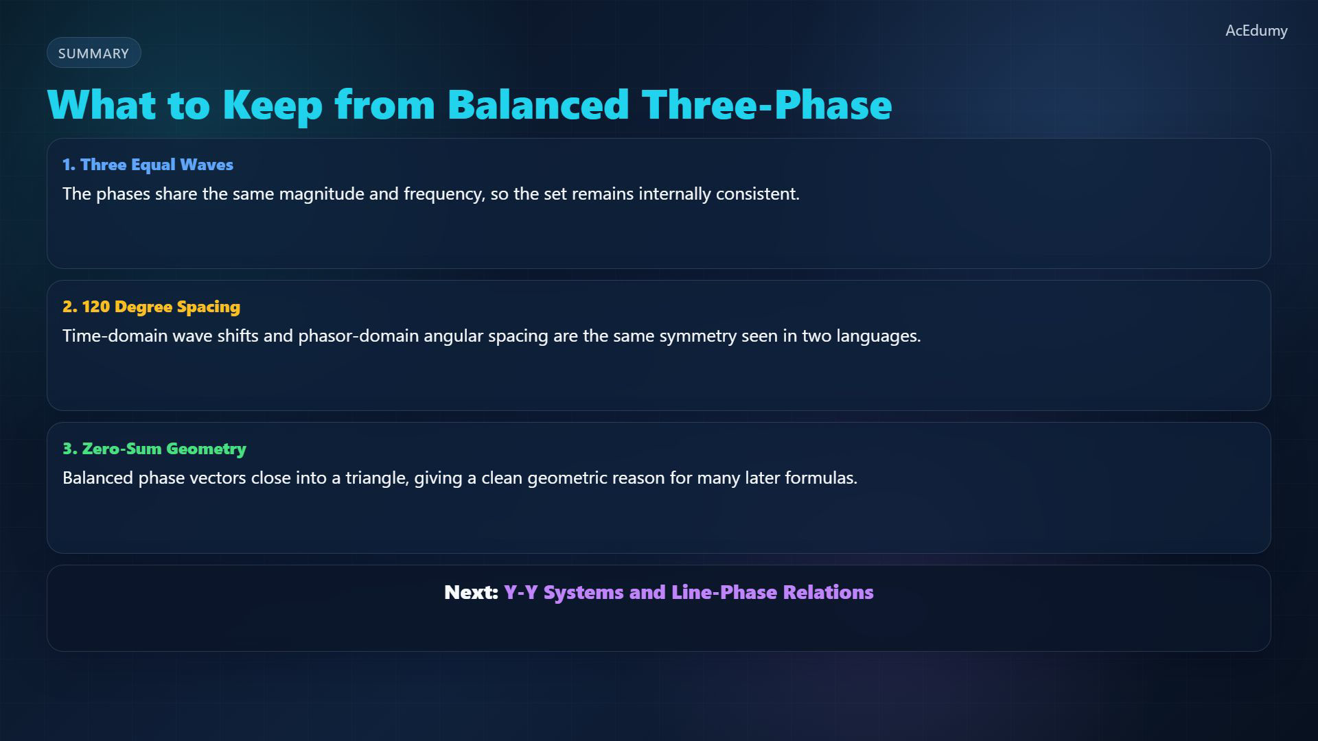
Existing-video still, not a newly rendered animation. The zero-sum step reuses the common-origin phasor card, not the source triangle with reversed B/C ordering. Fixed sine-reference RMS phasors and rotating-vector illustrations are distinguished in the text; waveform axes represent normalized voltage versus electrical angle. Keep equal frequency and 120° spacing; convert the common peak magnitude to RMS:Use one reference consistently in the waveform and phasor views. Zero sum alone is not sufficient to prove three-phase balance.Next: balanced wye-wye systems and line-to-phase relations. Keep phase voltages, line voltages and load currents distinct.Narration transcript
So the balanced three-phase picture is simple: equal magnitude, equal frequency, and one hundred twenty degree spacing. On the waveform plot and on the phasor plane, the same symmetry appears in two different languages. Next, we use that picture to connect phase quantities and line quantities.
Source video: Circuit Theory-2 #10 Balanced Three-Phase Intuition (2:21)