Circuit Theory 2 · Band-reject filters and passive examples
#23 Series-LC shunt notch, relative bandwidth, source/load resistance and loss
Read the LC shunt notch with full fractions, explicit output references, relative cutoff levels and practical loss/loading conditions.
Question
Study the initially relaxed, ideal real LTI passive voltage divider with constant positive L,C and a positive series resistance R feeding an output node. Connect L and C in series from that node to the common reference; measure output from the node to that reference. This is a series LC shunt, not a parallel LC tank. The existing final's topology drawing actually shows a parallel-looking LC connection and conflicts with the correct spoken series-branch description, so that frame is excluded. The input and output references remain explicit. For a lossless unloaded branch Z_b(s)=sL+1/(sC), H_N(s)=(s²LC+1)/(s²LC+sRC+1). Its stable poles describe the transient; zeros±jω0 set the ideal notch, with ω0=1/sqrt(LC) and f0=1/(2πsqrt(LC)). For positive frequency set X=ωL−1/(ωC): H_N(jω)=jX/(R+jX). The output gain vanishes at resonance and tends to unity as frequency tends to zero or infinity in this ideal model. Phase is undefined at exactly zero gain; immediately below the notch it tends to−90degrees, immediately above+90degrees. No physical component works ideally over unlimited frequency. Away from resonance means sufficiently far that branch impedance is large compared with surrounding resistance, not every frequency other than the exact center. The source says invert the idea conceptually: this is not reciprocal filtering. For the matching series RLC resistor-output band-pass H_BP=R/(R+jX), H_N+H_BP=1 as complex responses. Their squared magnitudes sum to1, their magnitudes do not. With x=ω/ω0 and Q=ω0L/R, notch magnitude=abs(1−x²)/sqrt((1−x²)²+(x/Q)²). Half-amplitude-squared edges relative to unity passband obey abs(X)=R, x1=(sqrt(4+1/Q²)−1/Q)/2 and x2=(sqrt(4+1/Q²)+1/Q)/2. Thus Δω=ω2−ω1=R/L, Δf=Δω/(2π), ω0=sqrt(ω1ω2) is the geometric—not arithmetic—center. Source center/bandwidth tick diagrams are schematic, not a quantitative linear-frequency assertion. Minus3dB is the rounded name; 20log10(1/sqrt2)=−3.0103dB. This amplitude definition is not an unconditional assertion of power transfer to a reactive output. At the ideal zero, log magnitude has a negative-infinite limit, not a finite numeric dB value. For a practical illustrative model let total source/series resistance R_t=R+R_s>0, load R_L>0, series branch loss r>=0, K=R_L/(R_t+R_L) and R_e=R_t parallel R_L. Then H=K(r+jX)/(R_e+r+jX), passband magnitude K, center magnitude K*r/(R_e+r). For r=0 any finite positive resistive load preserves the exact notch zero; source/load resistance changes relative width through R_e/L. For r>0 a load may weaken notch depth relative to passband. This qualifies the original can-weaken wording; do not assert that a resistive load by itself fills a lossless notch. With constant r and purely resistive surrounding elements the center stays at series-reactance cancellation. More general frequency-dependent loading/parasitics may shift it. Relative half-magnitude-squared crossings exist as two distinct edges only when (R_e+r)²−2r²>0; a shallow finite notch may never reach the−3dB level. Do not promise two cutoffs for every real filter. Positive branch loss raises the relative floor; depth and bandwidth are distinct design requirements. For L=10mH=.01H and C=100nF=1e−7F, f0=5032.92121Hz≈5.03kHz. Original speech supplies no numerical R. The excluded design frame additionally states source R=1kΩ; in the ideal unloaded model that would give Q≈.3162 and Δf≈15.915kHz, a broad reject band, not an established sharp design. SI prefixes are case-sensitive; its uppercase MH/NF kicker is excluded. Sensitivity for small deviations is δf0/f0≈−(δL/L+δC/C)/2; compute exact finite changes from the square root. RC low-pass output across C is1/(1+jωRC); grounded high-pass with series C and shunt R isjωRC/(1+jωRC), under ideal no-load assumptions. Original four-family mini-curves are qualitative shapes rather than the exact analytic RC/RLC functions and its bottom caption is cropped, so that frame is excluded. All eleven original final frames were individually reviewed. Five roles use approved reference cards from the same final: bandreject-idea and passive-examples→bridge; notch-topology→recipe; response-curve→wrap; design-example→center-frequency. The idea frame's numeric1/0 tick positions are inconsistent; response frame's numeric dB ticks and purported−3dB edge markers are wrong. The response frame's finite sampled dip is not evidence of actual component loss. Retained center/bandwidth diagrams use schematic equally spaced markers; retained source/load card has minor small-text proximity to box borders. All original say,11MP3s and46aligned cue boundaries remain unchanged. Cached-large ASR .8236–1 recognizes all critical topology,π and numeric design statements. The original passive-examples last sentence has a short divide-divide-idea repetition recognized by full cached-large and independent cached-small on both MP3/final excerpts; it remains in the audio and is a manual speech-fluency caveat, not silently repaired or claimed pristine. No numeric or sign correction was inferred from it. No alignment override,prompt or threshold change. This is an unpublished technical draft with explicit source/raster/teaching caveats,not complete human listening,motion QA or publication approval.
Written solution and narration transcript(shows the full solution)
Below are all the lines written in the notebook together with the full narration transcript.
1. Reject the middle frequency band
Reference from the same existing video. Five roles use approved explanation cards because the original topology, plot, units or layout are unsuitable; formulas and assumptions are stated in the notebook. Band-pass preserves a middle band in the previous ideal passive example.Now reverse which frequencies are retained; this does not mean taking the reciprocal transfer function.A narrow band-reject response is called a notch; frequencies well below and well above the rejected band pass.Narration transcript
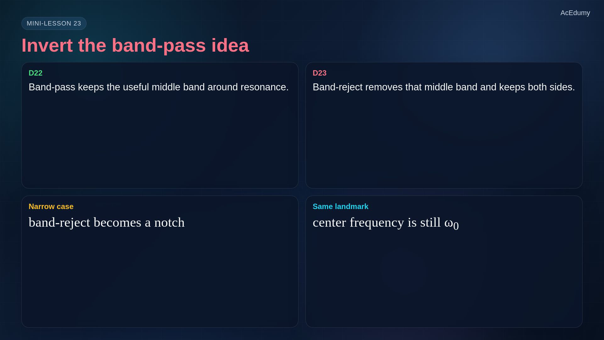
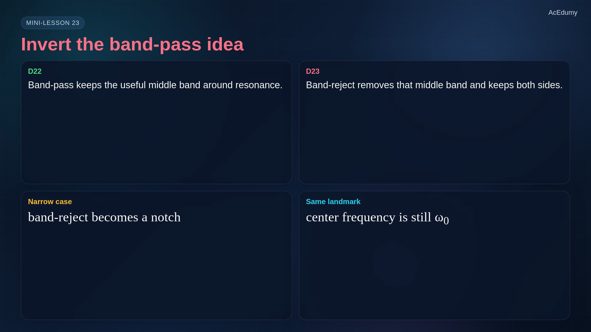
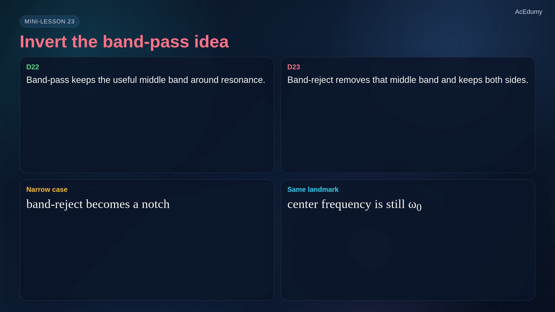
In the previous lesson, a band-pass filter kept a useful middle band around resonance. Now we invert that idea. A band-reject filter, also called a notch filter when it is narrow, passes low frequencies, passes high frequencies, and removes a band around one center frequency.
2. Identify the notch and relative edges
Reference from the same existing video. Five roles use approved explanation cards because the original topology, plot, units or layout are unsuitable; formulas and assumptions are stated in the notebook. Read the response against positive frequency with a stated gain reference.Far below and far above the notch, the ideal unloaded voltage gain approaches one.At the ideal center the series LC shunt has zero impedance and the output gain is zero.For a unity-passband ideal notch, the edge magnitudes are:Keep the lower and upper edge distinct from the center; angular reject bandwidth is:Narration transcript
The shape is easy to recognize. The gain is high on the left, drops around the center, and comes back on the right. The deepest point is the notch. The two minus-three-decibel points mark the reject-band edges. So the same landmarks return: center frequency, lower edge, upper edge, and bandwidth.
3. Connect a series LC shunt at the output

Reference from the same existing video. Five roles use approved explanation cards because the original topology, plot, units or layout are unsuitable; formulas and assumptions are stated in the notebook. Use a positive series resistor feeding the output node, then connect L and C in series from that node to the common reference.The lossless shunt branch is weakly loading only when its impedance magnitude is large relative to the surrounding resistance:At resonance the ideal branch shorts the output node through LC; with positive series R:Narration transcript
One passive way to make a notch is to put a resistor in series with the signal, then connect a series L C branch from the output node to ground. Away from resonance, that branch has high impedance, so the output node is not strongly loaded. At resonance, the L C branch becomes almost a short to ground, so the output voltage falls.
4. Keep angular and hertz resonance formulas distinct
Reference from the same existing video. Five roles use approved explanation cards because the original topology, plot, units or layout are unsuitable; formulas and assumptions are stated in the notebook. Use the ideal series-reactance cancellation condition to locate the notch.Keep the whole square-root product in each denominator:The center-frequency equation is shared with the corresponding resistor-output band-pass.The output and branch connection determine rejection versus passage; do not replace a series LC branch with a parallel LC branch.Narration transcript
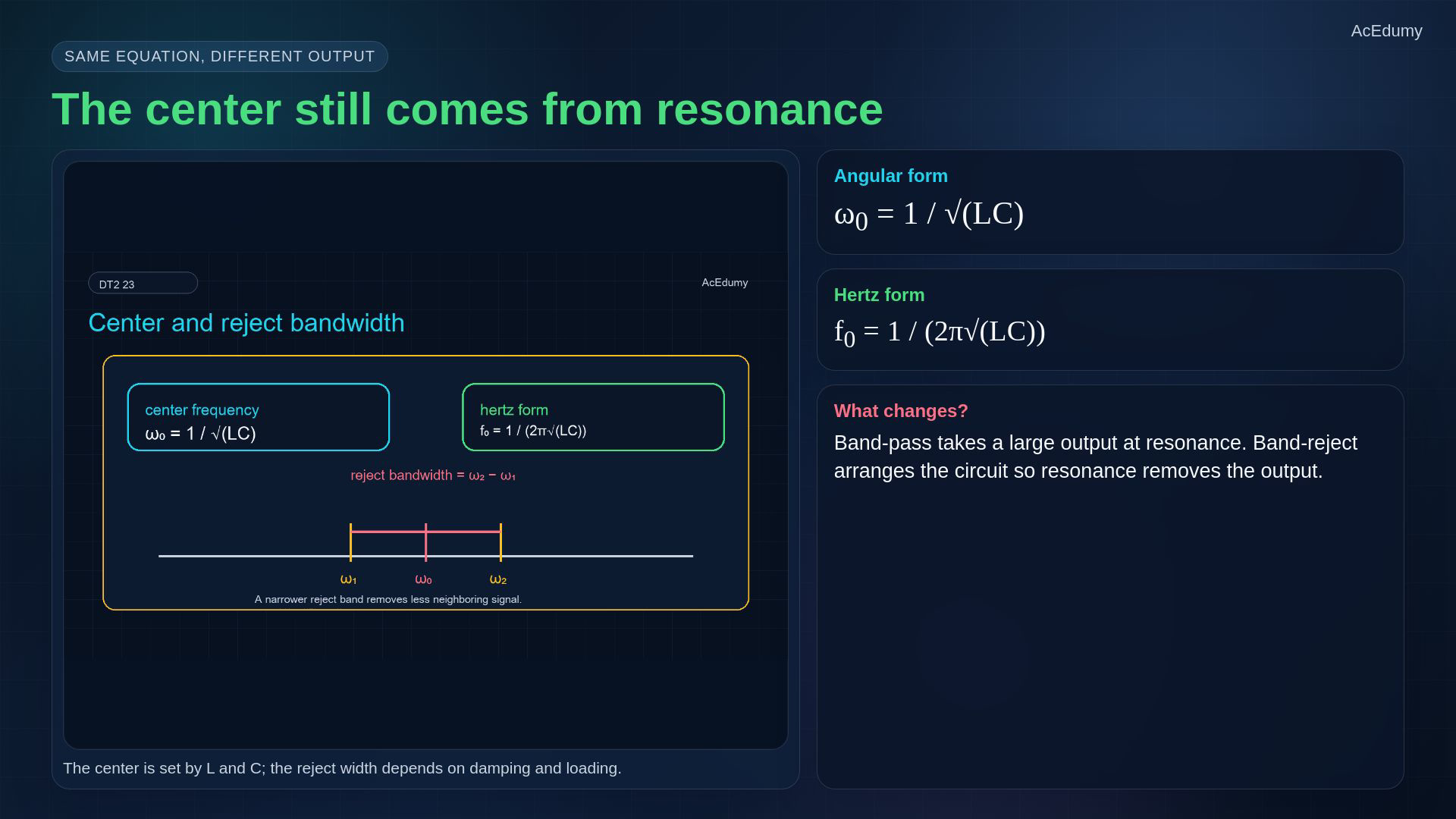
The center frequency comes from the same resonance condition as before. The angular center frequency is one over square root of L C, and the hertz form is one over two pi square root of L C. The difference is not the center equation. The difference is where we take the output and how the resonant branch is connected.
5. Separate ideal zero and lossy finite floor
Reference from the same existing video. Five roles use approved explanation cards because the original topology, plot, units or layout are unsuitable; formulas and assumptions are stated in the notebook. The ideal unloaded notch approaches zero decibels on both far sides of resonance.At the ideal zero, logarithmic gain tends to negative infinity; finite positive branch loss gives a nonzero floor.Measure notch depth relative to the actual passband and check the reject edges separately.Narration transcript
On the band-reject magnitude plot, the curve starts near zero decibels, dives near the center frequency, then returns near zero decibels. The ideal notch would reach negative infinity decibels, but real components have loss, so the notch has a finite floor. A practical filter is judged by both notch depth and reject bandwidth.
6. Distinguish rejection depth and bandwidth
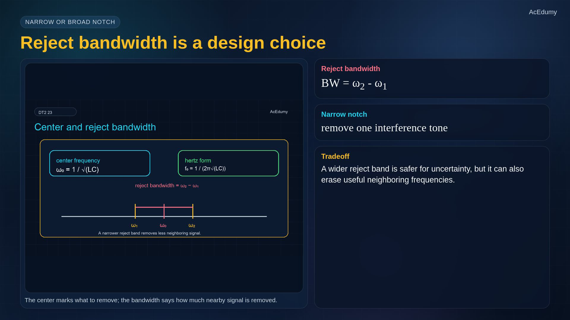
Reference from the same existing video. Five roles use approved explanation cards because the original topology, plot, units or layout are unsuitable; formulas and assumptions are stated in the notebook. Angular reject bandwidth is:A narrow notch can attenuate a selected interference tone; its attainable depth also matters.A wider reject band attenuates more neighboring frequencies.Choose bandwidth against interference uncertainty and the useful signal that must be retained.Narration transcript
The reject bandwidth is omega two minus omega one. A narrow notch removes a very specific interference tone, like hum or a switching spur. A wider reject band removes more neighboring content. That can be useful, but it can also damage signals close to the unwanted frequency.
7. Compare the four passive voltage responses
Reference from the same existing video. Five roles use approved explanation cards because the original topology, plot, units or layout are unsuitable; formulas and assumptions are stated in the notebook. Compare the four voltage-divider examples with their specified topology and output.Ideal unloaded RC low-pass, with output across C:Ideal unloaded RC high-pass, with series C and grounded output across R:For positive frequency, the series RLC resistor-output response is:The series-LC-shunt notch is:For these matched ideal RLC examples the complex responses, not their reciprocals, are complementary:Narration transcript
Now compare the passive examples. An R C low-pass keeps slow changes. An R C high-pass blocks slow changes. A series R L C band-pass keeps the middle band. An L C notch rejects the middle band. They all come from the same voltage-divider idea plus frequency-dependent impedance.
8. Calculate the LC notch center
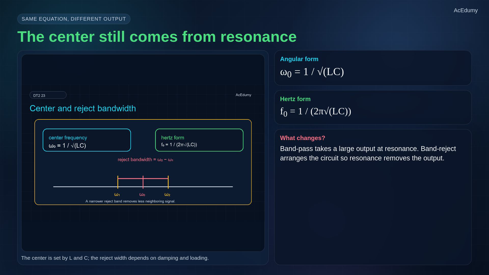
Reference from the same existing video. Five roles use approved explanation cards because the original topology, plot, units or layout are unsuitable; formulas and assumptions are stated in the notebook. Calculate the nominal notch center before choosing a practical bandwidth.For an inductance of ten millihenries and capacitance of one hundred nanofarads:Connect the LC pair in series as a shunt, and include the surrounding resistance when setting damping.A sharp and deep notch needs both suitable damping and low branch loss; include source and load effects.Narration transcript
Here is a quick notch design. If L is ten millihenries and C is one hundred nanofarads, the center frequency is about five point zero three kilohertz. Place the series L C branch as a shunt at the output node, and use the surrounding resistance to control damping. For a sharp and deep notch, source resistance, load resistance, and component losses must be included.
9. Include source, load, loss and tolerance
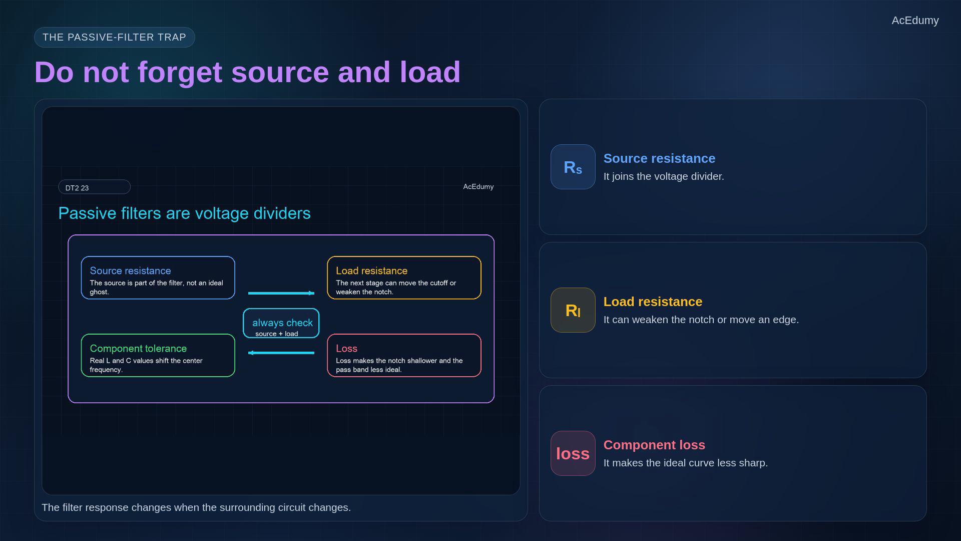
Reference from the same existing video. Five roles use approved explanation cards because the original topology, plot, units or layout are unsuitable; formulas and assumptions are stated in the notebook. Include the signal source and the receiving stage in the filter model.The filter is a voltage divider between stages, not an isolated impedance.With finite branch loss a resistive load can weaken rejection relative to passband; a resistive load alone does not remove an ideal zero.Positive component deviations shift the nominal center; recalculate from the actual L and C.Narration transcript
The biggest passive-filter trap is forgetting the source and the load. A filter is not floating in space; it is a voltage divider connected between stages. A load can move the cutoff, reduce the notch depth, or change the effective Q. Component tolerance shifts the center frequency as well.
10. Check topology and operating assumptions

Reference from the same existing video. Five roles use approved explanation cards because the original topology, plot, units or layout are unsuitable; formulas and assumptions are stated in the notebook. Use a four-part passive-filter check.Specify which frequencies should pass and which should be attenuated.Choose the topology and both output terminals; RC and resonant LC/RLC arrangements do different jobs.For the ideal notch, calculate the center using:Check source resistance, load, loss and tolerance before trusting the ideal curve.Narration transcript
A practical recipe is this. First decide what you want to pass and what you want to reject. Second choose the passive topology: R C for one-sided filters, R L C or L C for middle-band behavior. Third compute the landmark frequency. Fourth check loading, loss, and tolerance before trusting the curve.
11. Summarize the passive notch
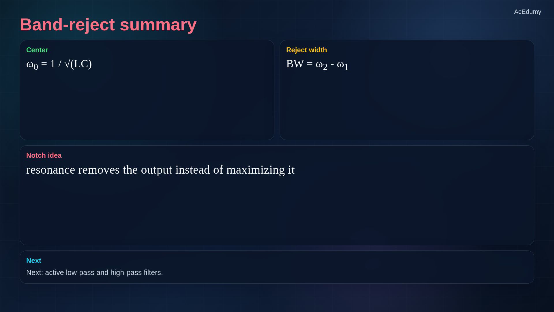
Reference from the same existing video. Five roles use approved explanation cards because the original topology, plot, units or layout are unsuitable; formulas and assumptions are stated in the notebook. Summary: preserve the sides and attenuate the middle band.A band-reject filter passes the low and high frequency regions relative to its notch.A narrow rejected band is called a notch.A series LC branch to ground after a positive series resistor gives the ideal passive notch example.Center and reject width are distinct:Narration transcript
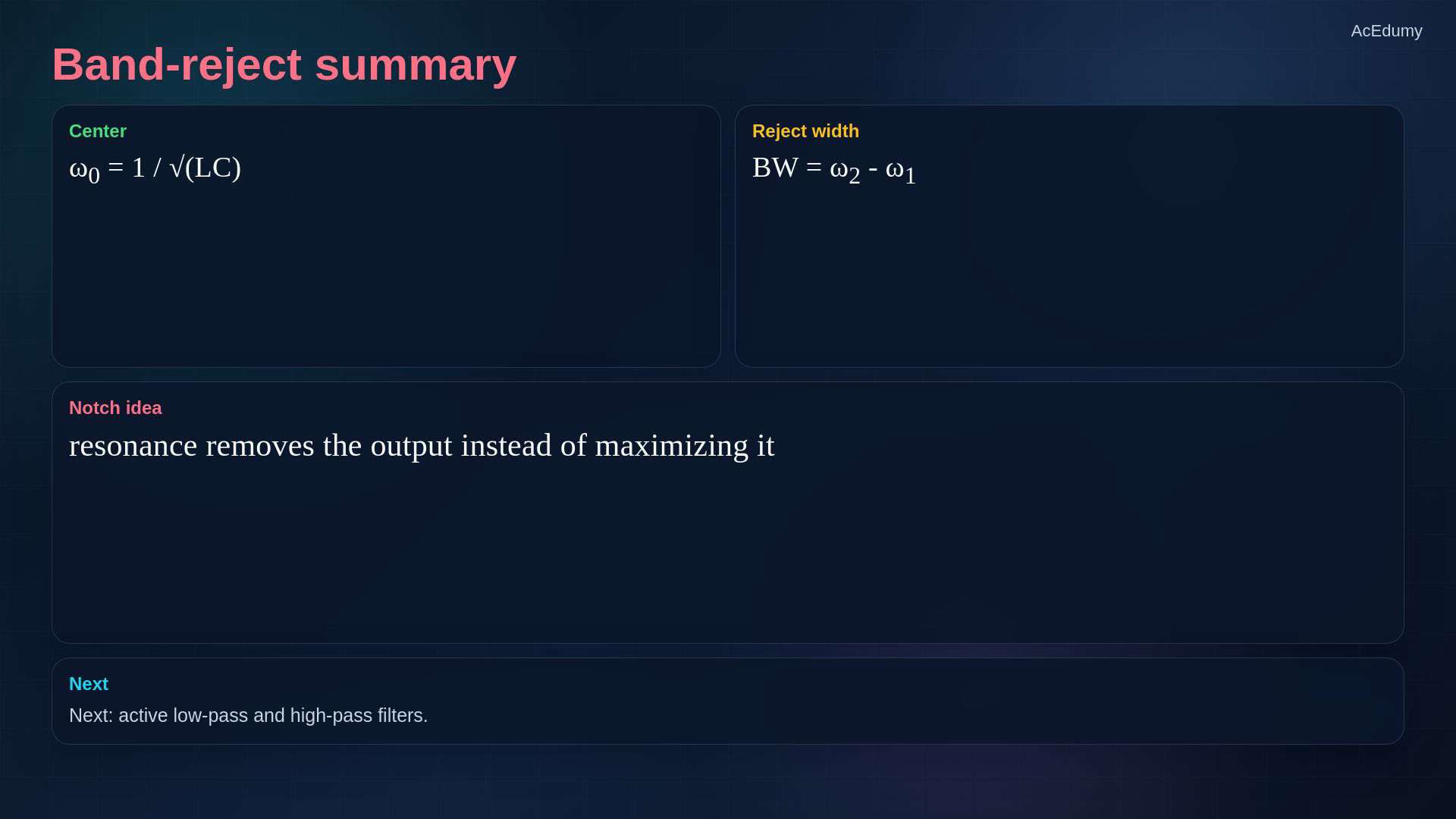
Summary. A band-reject filter passes both sides and removes the middle. A narrow band-reject filter is a notch filter. A series L C shunt branch gives a clean passive notch example. The same resonance formula sets the center, while loading and losses decide how deep and how wide the rejection becomes.
Source video: Circuit Theory-2 #23 | Band-Reject Filters and Passive Filter Examples (4:23)