Electronics 1 · Electronics Basics
#16 BJT emitter-bias circuit — complete DC analysis
Use emitter-resistor negative feedback to calculate every current and voltage at a stable BJT operating point.
Question
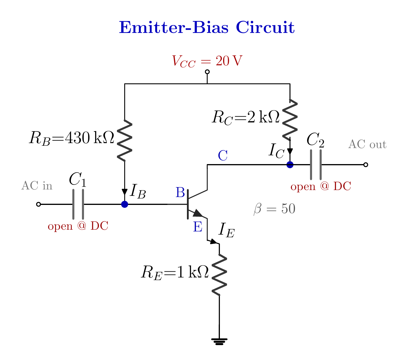
For the emitter-bias NPN circuit with V_CC = 20 V, R_B = 430 kΩ, R_C = 2 kΩ, R_E = 1 kΩ, β = 50, and V_BE ≈ 0.7 V, find I_B, I_C, I_E, V_E, V_B, V_C, V_CE, and V_BC, then verify the operating region.
Written solution and narration transcript(shows the full solution)
Below are all the lines written in the notebook together with the full narration transcript.
1. Why fixed bias drifts
C_1 and C_2 are open at DC, while R_E carries I_E. Fixed bias:A changing β moves the Q pointAdd RE in the emitter legRE creates negative feedbackTarget: a steadier operating pointNarration transcript
Welcome back. Last time we cracked our first transistor circuit, the fixed-bias circuit, wide open: the base current, the collector current, every voltage. But I closed with a warning. That simple circuit likes to drift, and here is why. In fixed-bias, the base current depends only on R sub B, and the collector current is just beta times that. So I sub C rides entirely on beta. And beta is a slippery number. Swap in another transistor of the very same type, and beta might jump from fifty to a hundred and fifty. Your collector current triples. Your carefully chosen operating point slides toward saturation, and the amplifier clips. Today we fix that, and the fix is almost insulting in its simplicity: we drop one resistor into the emitter leg. That single resistor, R sub E, tames the drift. Let us see exactly how, by solving the circuit completely.
2. Reduce the DC circuit
C_1 and C_2 are open at DC, while R_E carries I_E. C1 and C2 are open at DCThe AC signal path stays out of the DC calculationFind every DC current and voltageNarration transcript
Here is the circuit, and at a glance it is the fixed-bias circuit with one new piece. A twenty volt supply, V sub C C, feeds the base through R sub B, four hundred thirty kilo-ohms, and the collector through R sub C, two kilo-ohms. Beta is fifty, same as before. The new piece is down at the emitter. Instead of wiring it straight to ground, we send it to ground through R sub E, one kilo-ohm. That little resistor is the whole story of this lesson. As always, the two capacitors are open circuits in D C. They keep the A C signal out of our D C analysis, so we ignore them. The question asks for everything: the base current I sub B, the collector current I sub C, and the voltages V sub E, V sub B, V sub C, V sub C E, and V sub B C. Let us walk it, exactly as we did before.
3. Base loop
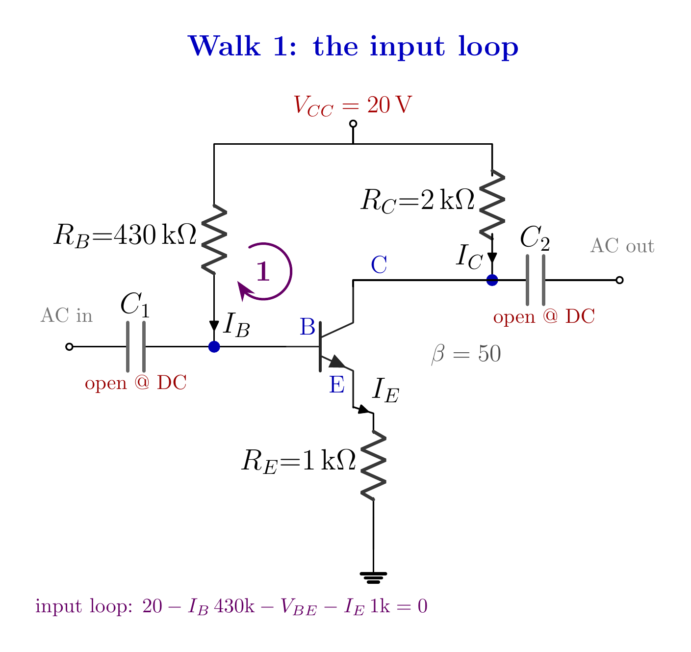
The drop across R_E is I_E R_E in the base loop. RE appears as 51 kΩ from the baseNarration transcript
Same tool as always, Kirchhoff's voltage law, and the same walk. We start at the supply, twenty volts. The current out through the four hundred thirty k resistor has only one path, into the base, so it is I sub B. First obstacle: R sub B. We pay the toll, minus I sub B times four hundred thirty k, and we arrive at the base. One step across the base-emitter junction, minus 0.7, and we land on the emitter. Now, here is the new trap, and it is the single most common mistake in this circuit. We still have to walk down through R sub E to reach ground, so we pay another toll: minus the current through R sub E, times one k. But which current flows through R sub E? It is tempting to write I sub B. Resist that. The emitter resistor carries the emitter current, I sub E. Everything that came in the base, plus everything that came in the collector, pours out of the emitter. And we already know the relationship: I sub E equals beta plus one times I sub B, that is fifty-one times I sub B. So the toll across R sub E is minus fifty-one I sub B times one k. Now we reach ground, zero. The full walk reads: twenty, minus I sub B times four hundred thirty k, minus 0.7, minus fifty-one I sub B times one k, equals zero. One unknown, I sub B, exactly what we wanted. Let us collect it. Twenty minus 0.7 is 19.3. On the other side, I sub B times four hundred thirty k, plus I sub B times fifty-one k, because fifty-one times one k is fifty-one k. Add them: I sub B times four hundred eighty-one k. Pause on that fifty-one k, because it is the secret of this circuit. The one kilo-ohm in the emitter, seen from the base, looks like fifty-one kilo-ohms. Beta plus one multiplies it. A small emitter resistor casts a giant shadow on the base loop, and that giant shadow is what will steady our current. So, 19.3 equals I sub B times four hundred eighty-one k. I sub B is 19.3 divided by four hundred eighty-one k. Volts over ohms gives amps: 4.01 times ten to the minus five amps, which is 40.1 microamps. Magnitude check: base currents live in microamps, and forty is right in the healthy thirty to eighty band. We are on track.
4. Three transistor currents
C_1 and C_2 are open at DC, while R_E carries I_E. IE ≈ 2.046 mAIC ≈ 2.006 mANarration transcript
I sub B is on the board, and the two currents that depend on it fall out in one line each. The emitter current we already used: I sub E equals fifty-one times I sub B, fifty-one times 40.1 microamps, which is two thousand forty-six microamps. Slide the decimal three places: 2.046 milliamps. The collector current: I sub C equals beta times I sub B, fifty times 40.1 microamps, two thousand five microamps, that is 2.006 milliamps. Magnitude check: collector currents live in milliamps, and two milliamps is exactly right. And notice, 2.006 and 2.046 are practically twins. There it is again, our old promise: I sub C is approximately I sub E.
5. Emitter feedback
C_1 and C_2 are open at DC, while R_E carries I_E. VE = (2.046 mA)(1 kΩ)Current ↑ → VE ↑ → VBE ↓Feedback opposes the changeNarration transcript
Now for something the fixed-bias circuit never gave us: a voltage at the emitter. Before, the emitter sat at ground, zero volts. Not anymore. The emitter current flows through R sub E, so the emitter floats up. V sub E equals I sub E times R sub E: 2.046 milliamps times one k. Milliamps times kilo-ohms gives volts directly: 2.046 volts. And the base? Use the junction we trust. V sub B E is V sub B minus V sub E, and it equals 0.7. So V sub B equals 0.7 plus V sub E, 0.7 plus 2.046, which is 2.746 volts. Now look back at this emitter voltage, because it is the hero of the whole story. Suppose beta were larger, and the collector current tried to climb. More current through R sub E means a higher V sub E. But V sub B is roughly pinned by the base loop. So a rising V sub E squeezes V sub B E, the base-emitter drop, and a smaller V sub B E throttles the base current right back down. The emitter resistor is a leash: the harder the current pulls, the harder the leash pulls back. That self-correction is exactly why the emitter-bias point barely drifts, while the fixed-bias point wandered.
6. Collector loop
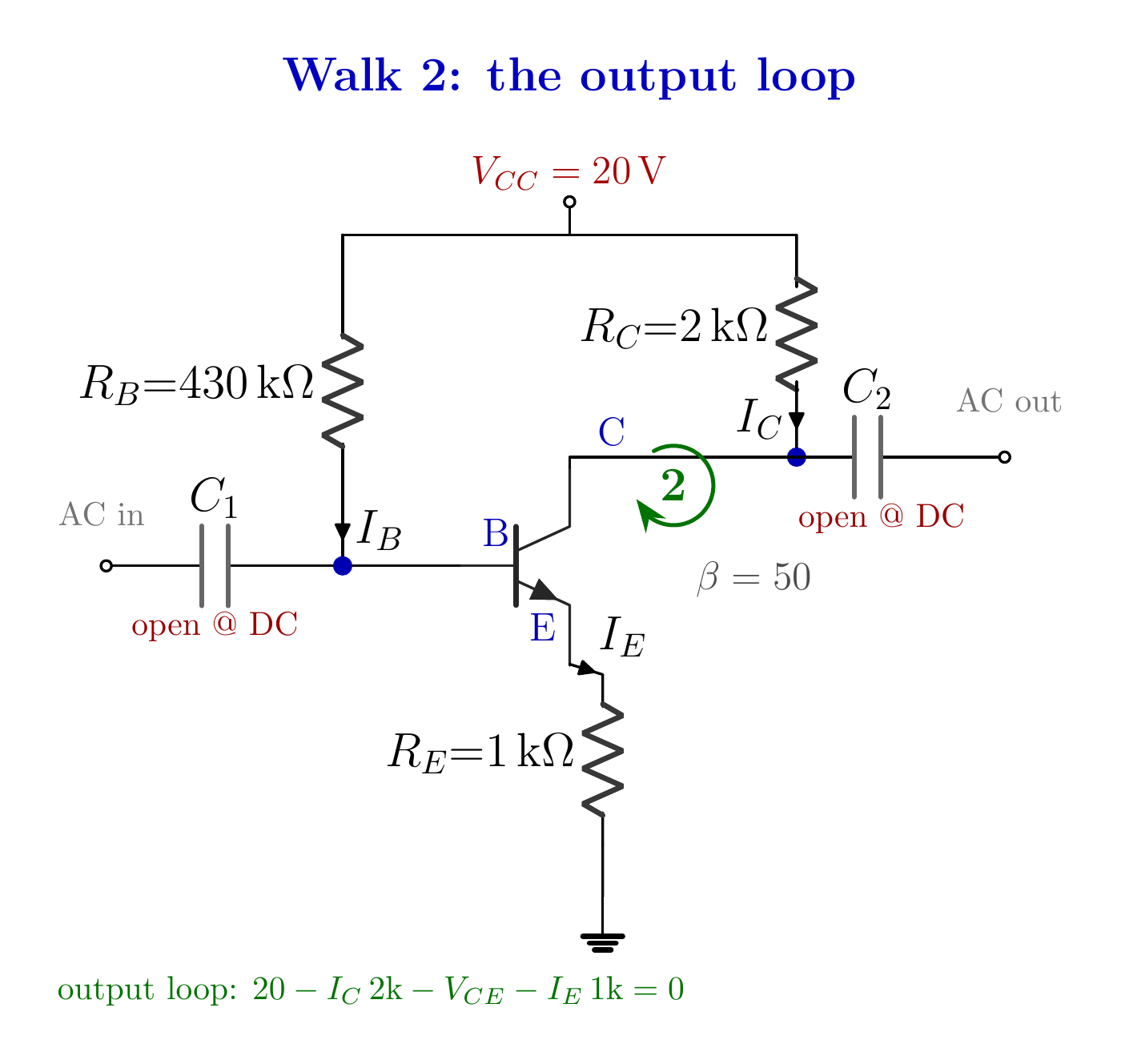
The output loop determines V_CE and closes the supply-voltage check. B-C reverse biased → active regionNarration transcript
One walk left, on the collector side, and it hands us the last three voltages. Start at twenty volts, down through R sub C. The current there is I sub C, and we know it, 2.006 milliamps. The resistor eats I sub C times two k: 2.006 times two is about 4.01 volts. So the collector sits at V sub C equals twenty minus 4.01, which is 15.99 volts. Now the first-minus-second rule, our rule for life: V sub C E is V sub C minus V sub E. 15.99 minus 2.05 is about 13.94 volts. That is V sub C E. And the last one: V sub B C is V sub B minus V sub C, 2.75 minus 15.99, which is minus 13.24 volts. Negative, and just like last time, that minus sign is good news. It means the base-collector junction is reverse biased, and together with the forward-biased base-emitter junction, that is the signature of the active region: the transistor is amplifying, healthy. One sanity check before we close. The supply should split entirely across the three drops: the collector resistor takes 4.01, V sub C E takes 13.94, the emitter resistor takes 2.05. Add them: twenty volts, exactly. Nothing leaked.
7. Method summary
C_1 and C_2 are open at DC, while R_E carries I_E. Walk from a known voltageNew element: the emitter resistorRE carries IE, not IBBase loop sees (β + 1)RENegative feedback reduces β driftIC ≈ 2.01 mA; VCE ≈ 13.94 VNext: voltage-divider biasNarration transcript
Let us pocket the lesson. The method never changed: start at a voltage you know, and pay every obstacle around the loop. The only new twist was the emitter resistor. It carries the emitter current, not the base current, so in the base loop it counts as beta plus one times its value. And that is the whole point of this circuit. In fixed-bias, beta lived only on top, so the operating point rode entirely on it. Here, beta also sits underneath, in the denominator. When beta grows, the bottom grows with it, and the current barely moves. That is the negative feedback the emitter resistor buys you, and it is why the emitter-bias point holds steady while the fixed-bias point wandered. Our circuit came to rest at a comfortable, stable point: forty microamps, two milliamps, and a collector-emitter voltage of about fourteen volts. Next time we push the idea one step further with the voltage-divider bias, the configuration real designs actually use. See you there.