Electronics 1 · Electronics Basics
#15 BJT fixed-bias circuit — complete DC analysis
Walk the base and collector loops of a fixed-bias NPN circuit to determine every quiescent current and voltage.
Question
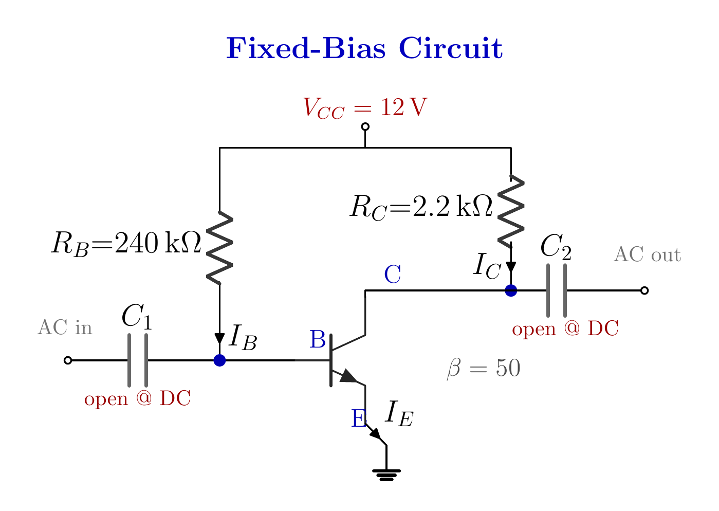
For the grounded-emitter fixed-bias NPN circuit with V_CC = 12 V, R_B = 240 kΩ, R_C = 2.2 kΩ, β = 50, and V_BE ≈ 0.7 V, find I_BQ, I_CQ, V_B, V_C, V_BC, and V_CEQ.
Written solution and narration transcript(shows the full solution)
Below are all the lines written in the notebook together with the full narration transcript.
1. Model recap
The input and output capacitors are open circuits in DC analysis. Small IB → large ICNew target: the Q pointFind every DC valueNarration transcript
Welcome back. Last time we met the transistor: a current-controlled valve, where a tiny base current commands a collector current beta times larger. And we packed two golden facts for the road: V sub B E is 0.7 volts, and I sub C is beta times I sub B. Today we put all of that to work. Our first real transistor circuit is waiting, the fixed-bias circuit, and we will solve it completely: both currents, and every voltage in sight.
2. Simplify the circuit
The input and output capacitors are open circuits in DC analysis. Emitter → groundC1 and C2 are open at DCFind IB, IC, VB, VC, VBC, VCEQ = quiescent operating pointNarration transcript
Here is our first transistor circuit, and the simplest possible way to bias one. It is called the fixed-bias circuit. A twelve volt supply, V sub C C, feeds two branches. One branch goes through R sub B, two hundred forty kilo-ohms, into the base. The other goes through R sub C, 2.2 kilo-ohms, into the collector. The emitter is wired straight to ground. Beta is fifty. You also see two capacitors, where the A C signal would come in and out. But remember: in D C analysis, a capacitor is an open circuit. They are there precisely to keep A C out of our D C story. So those two wires simply drop out of the picture. The question asks for: I sub B Q, I sub C Q, V sub B, V sub C, V sub B C, and V sub C E Q. Now, do not let the Q scare you. Q stands for quiescent, the quiet resting point. It just means the D C operating value. Find I sub B Q simply means: find I sub B.
3. Base loop
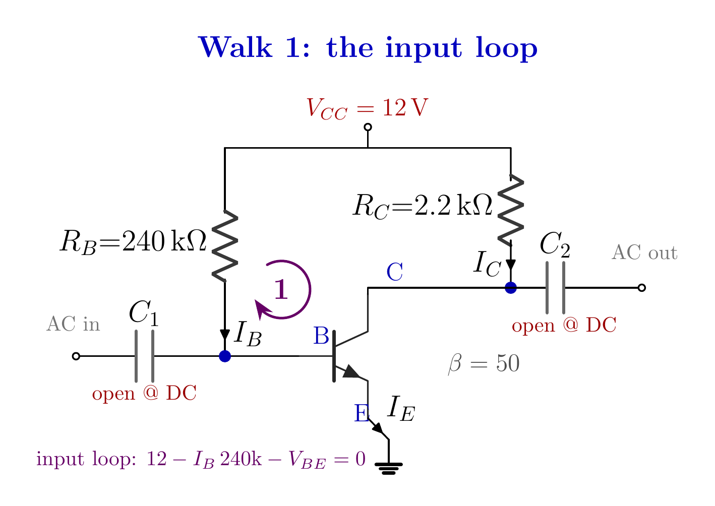
The first KVL walk determines I_B. Choose a one-unknown KVLUnit check:Magnitude check: base current in μANarration transcript
For a circuit like this we really have one tool, Kirchhoff's voltage law. But let me teach you how to walk it, because this is where most people struggle. We start our journey at the supply, at twelve volts. Which current flows out through the two hundred forty k resistor? There is only one path here, and it feeds the base. So that current is I sub B itself. First obstacle on the road: R sub B. We pay the toll: minus I sub B times two hundred forty k. And we arrive at the base. Now, here is the trap almost everyone falls into. You feel like the walk must continue all the way down to ground, no matter what. It does not. You may stop at any point whose voltage you know. And before writing anything, ask one question: does this line reduce my unknowns to one? If I stop here and write, equals V sub B, I have two unknowns, I sub B and V sub B. That line is useless. So what do we actually know? We know the base to emitter drop: 0.7 volts. So take one more step, across the junction, minus 0.7, and now I am standing on the emitter. And the emitter is wired to ground: zero volts. I have arrived. So the full walk reads: twelve, minus I sub B times two hundred forty k, minus 0.7, equals zero. One unknown. Twelve minus 0.7 is 11.3 volts. So I sub B equals 11.3 divided by two hundred forty k. Volts divided by ohms gives amps. 11.3 over two hundred forty thousand is 4.71 times ten to the minus five amps. Ten to the minus six is micro, so this is 47.1 microamps. Quick magnitude check. Base currents live in microamps. Thirty to eighty microamps, you are healthy. If you found milliamps, you almost certainly forgot the kilo in two hundred forty k. Any trouble so far? I do not think so.
4. Collector current
The input and output capacitors are open circuits in DC analysis. IC ≈ 2.35 mAMagnitude check: collector current in mAIE ≈ 2.40 mANarration transcript
I sub B is ticked. Who is next? I sub C, and it is one line. I sub C equals beta times I sub B: fifty times 47.1 microamps. Fifty times 47.1 is two thousand three hundred fifty-five. So two thousand three hundred fifty-five microamps. Slide the decimal three places: 2.35 milliamps. And the magnitude rule again: collector currents live in milliamps, a few milliamps is exactly what we expect. While we are here, the emitter current: beta plus one, fifty-one, times 47.1 microamps is about 2.4 milliamps. 2.35 and 2.4, nearly the same, just as we promised: I sub C is approximately I sub E.
5. Collector loop
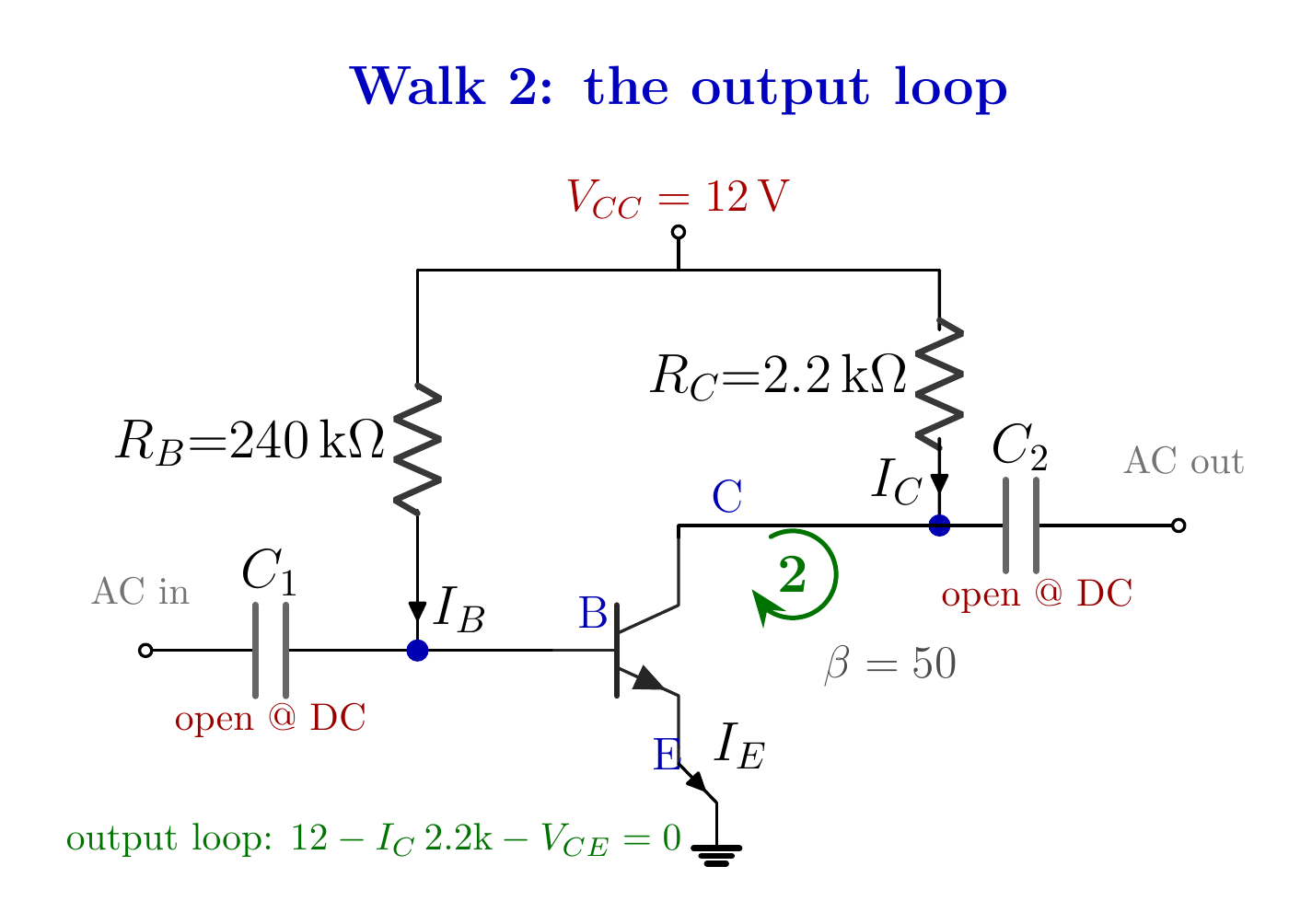
The second KVL walk determines V_CE. VRC = (2.35 mA)(2.2 kΩ)mA × kΩ = VCheck:Narration transcript
Now the second walk, on the collector side. Again we start at twelve volts. Which current flows through the 2.2 kilo-ohm resistor? We are on the collector branch, so it is I sub C. And the beautiful part: this time we know it. 2.35 milliamps. So, the obstacle: minus I sub C times 2.2 k. 2.35 times 2.2 is about 5.18. And here units take care of themselves: milliamps times kilo-ohms gives volts directly. So the resistor eats 5.18 volts, and I arrive at the collector. From the collector, one step across the transistor, minus V sub C E, brings me to the emitter: ground, zero. Twelve, minus 5.18, minus V sub C E, equals zero. So V sub C E equals twelve minus 5.18, which is 6.82 volts. Sanity check before moving on: 5.18 plus 6.82 is exactly twelve. The whole supply is accounted for. Nothing leaked. Lovely.
6. Remaining voltages
The input and output capacitors are open circuits in DC analysis. B-C junction is reverse biasedOperating region: activeNarration transcript
Let us take inventory. I sub B, found. I sub C, found. V sub C E, found. Who is left? V sub B, V sub C, and V sub B C. And for these I will hand you a rule that pays rent forever. Any voltage with two subscripts is simply: first minus second. V sub C E is V sub C minus V sub E. Always. Do not forget this one. So, what is V sub E? The emitter is wired to ground, so V sub E is zero volts. Then V sub C E equals V sub C minus zero, which means V sub C is just V sub C E: 6.82 volts. Found, for free. Same trick for the base. V sub B E is V sub B minus V sub E, and that is 0.7. With V sub E zero, V sub B is 0.7 volts. Also free. Notice we never touched the circuit again. Last one: V sub B C, first minus second, V sub B minus V sub C. 0.7 minus 6.82. That is minus 6.12 volts. Negative. Should that worry you? Not at all. The base should sit at a lower voltage than the collector. A negative V sub B C tells you the base to collector junction is reverse biased. And that, together with the forward biased base to emitter junction, is exactly the recipe for the active region, the region where the transistor amplifies. That minus sign is the circuit telling you: I am healthy.
7. Method summary
The input and output capacitors are open circuits in DC analysis. 1) Open capacitors at DC2) Base KVL → IB4) Collector KVL → VCEIB = 47.1 μA; IC = 2.35 mANarration transcript
Let us bring it all together. The B J T is a current-controlled valve: a tiny base current commands a collector current beta times larger. Two golden facts unlock the D C analysis: V sub B E is 0.7 volts, and I sub C is beta times I sub B. The method is a walk: start at a voltage you know, pay every obstacle on the road, and stop at any point whose voltage you know. You do not have to reach ground. For double subscripts, first minus second, always. And keep your magnitude radar on: base currents in microamps, collector currents in milliamps. Our fixed-bias circuit came to rest at 47.1 microamps, 2.35 milliamps, and a V sub C E of 6.82 volts. Next time, we put a resistor under the emitter, and discover why this simple bias likes to drift, and how that one resistor pins it down. See you there.