Electronics 1 · Electronics Basics
#17 BJT voltage-divider bias — exact Thevenin analysis
Collapse a loaded divider into its Thevenin equivalent, solve the exact BJT operating point, and test its stability against β variation.
Question
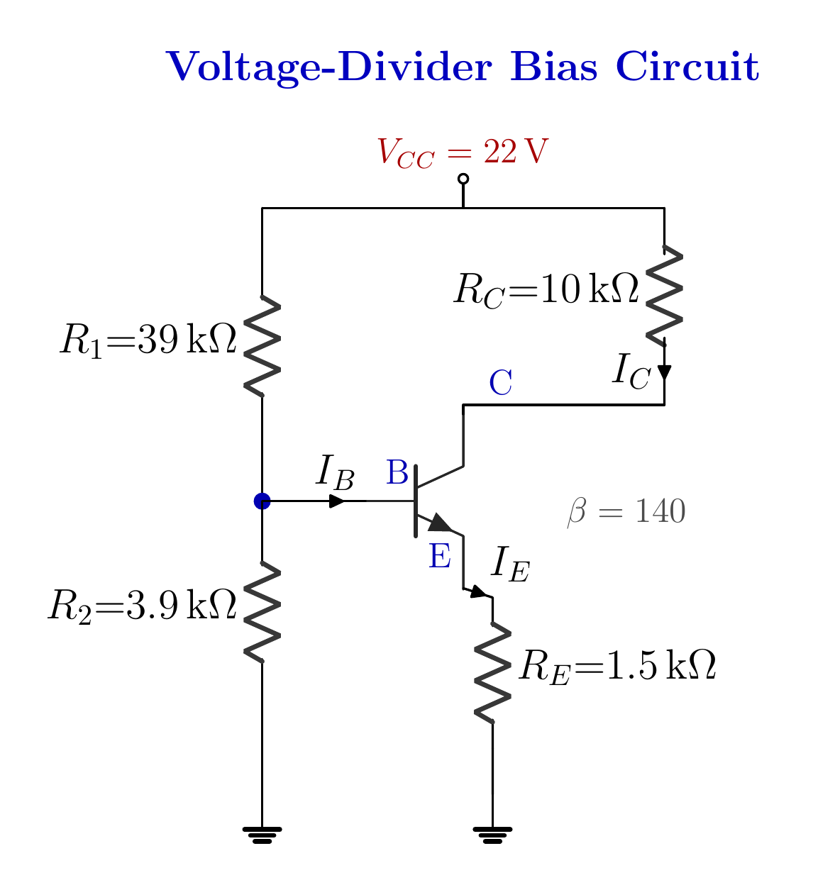
For the NPN voltage-divider bias circuit with V_CC = 22 V, R_1 = 39 kΩ, R_2 = 3.9 kΩ, R_C = 10 kΩ, R_E = 1.5 kΩ, and β = 140, form the Thevenin equivalent and find I_B, I_C, I_E, and V_CE by exact analysis. Explain divider loading and stability against β variation.
Written solution and narration transcript(shows the full solution)
Below are all the lines written in the notebook together with the full narration transcript.
1. Why a voltage divider?
The base loads the divider, so the exact solution uses a Thevenin equivalent. Fixed bias makes IC depend directly on βR1-R2 holds VB from outsideRE holds current by negative feedbackGoal: little Q-point motion as β changesExact tool: the Thevenin equivalentNarration transcript
Welcome back. Last time the emitter resistor earned its keep: it put beta into the denominator, and our operating point stopped wandering. But I have a confession. Beta is still in the formula, and a leash that depends on the dog is only half a leash. Real designs go one step further. They stop asking the transistor to set its own base voltage, and instead they hold that voltage from outside, with two plain resistors: a voltage divider. And here is the promise of today's lesson, because it sounds almost too good. At the end, we will swap our transistor for one with four times the beta. Four times. And we will watch the collector current move by about one percent. To earn that, we first solve the circuit exactly, and along the way we pick up one of the most powerful tools in all of circuit theory: the Thevenin equivalent.
2. Circuit and loading trap
The base loads the divider, so the exact solution uses a Thevenin equivalent. The base taps the divider midpointBase current loads the dividerThe plain divider rule is exact only when unloadedNarration transcript
Here is the circuit. A twenty-two volt supply sits at the top. The collector path is familiar: down through R sub C, ten kilo-ohms, into the collector. The emitter goes to ground through R sub E, 1.5 kilo-ohms. Our leash from last time, still on duty. Beta is one hundred forty. The new part is on the left. Two resistors stacked between the supply and ground: R one, thirty-nine kilo-ohms on top, and R two, 3.9 kilo-ohms at the bottom. And the base taps the point between them. That stack is a voltage divider, and its job is to hold the base at a fixed voltage, no matter what the transistor gets up to. The question asks for the collector current and V sub C E. Now, here is the tempting shortcut. You look at those two resistors and you want to use the divider formula, call the base two volts, and move on. Resist that, for now. The divider formula is only exact when nothing draws current from the midpoint. But our base does draw current. The divider is loaded. Today we respect that loading and solve the circuit exactly. And for that, we need a tool that can swallow the supply and both resistors, and hand us back something simple.
3. Find R_Th
The base loads the divider, so the exact solution uses a Thevenin equivalent. Switch off the independent voltage sourceIdeal voltage source → short circuitFrom the base: R1 ∥ R2Narration transcript
The tool is called the Thevenin equivalent, and the idea deserves a slow look, because you will use it for the rest of your life. Stand where the base stands, and look left, into the wall formed by the supply and the two resistors. Here is the key insight: the base cannot see behind that wall. It only feels two things. How hard the wall pushes, and how much the wall resists. So if we replace the entire wall with one battery and one resistor that push and resist in exactly the same way, the transistor will never know the difference. Finding those two numbers takes two short experiments. Experiment one gives the resistance. Switch the supply off. A dead voltage source is just a wire, so the top of R one drops down to ground. Now look into the terminal again: R one to ground, R two to ground, both leaving from the same point. Two resistors from the same point to the same place. That is a parallel pair. Watch them merge. Product over sum. Thirty-nine times 3.9 is 152.1. Thirty-nine plus 3.9 is 42.9. Divide them: 3.545 kilo-ohms. That single resistor is experiment one's answer: the Thevenin resistance.
4. Find V_Th
The base loads the divider, so the exact solution uses a Thevenin equivalent. Leave the base terminal openIdiv = 22/(39 kΩ + 3.9 kΩ)Idiv = 0.5128 mAVTh = Idiv R2Left network → 2 V source + 3.545 kΩNarration transcript
Experiment two gives the voltage. Switch the supply back on, and leave the base terminal disconnected. No load, nothing drawing current. Now the only path for current is straight down the stack: out of twenty-two volts, through thirty-nine k, through 3.9 k, to ground. One loop, one current. Twenty-two volts divided by the total, 42.9 kilo-ohms. Volts over kilo-ohms gives milliamps: 0.5128 milliamps. Keep an eye on that number, by the way. Half a milliamp, flowing down the ladder. It returns at the end of the story. The open terminal sits at the top of R two, so its voltage is this current times 3.9 k. 0.5128 times 3.9: almost exactly two volts. That is the Thevenin voltage. And now the magic moment: the wall collapses. The supply and both resistors fold into a single two volt battery behind a single 3.545 kilo-ohm resistor. The base feels exactly what it felt before. But the left side of our circuit is now one battery and one resistor. We have just made this problem look exactly like the last two lessons.
5. Base loop
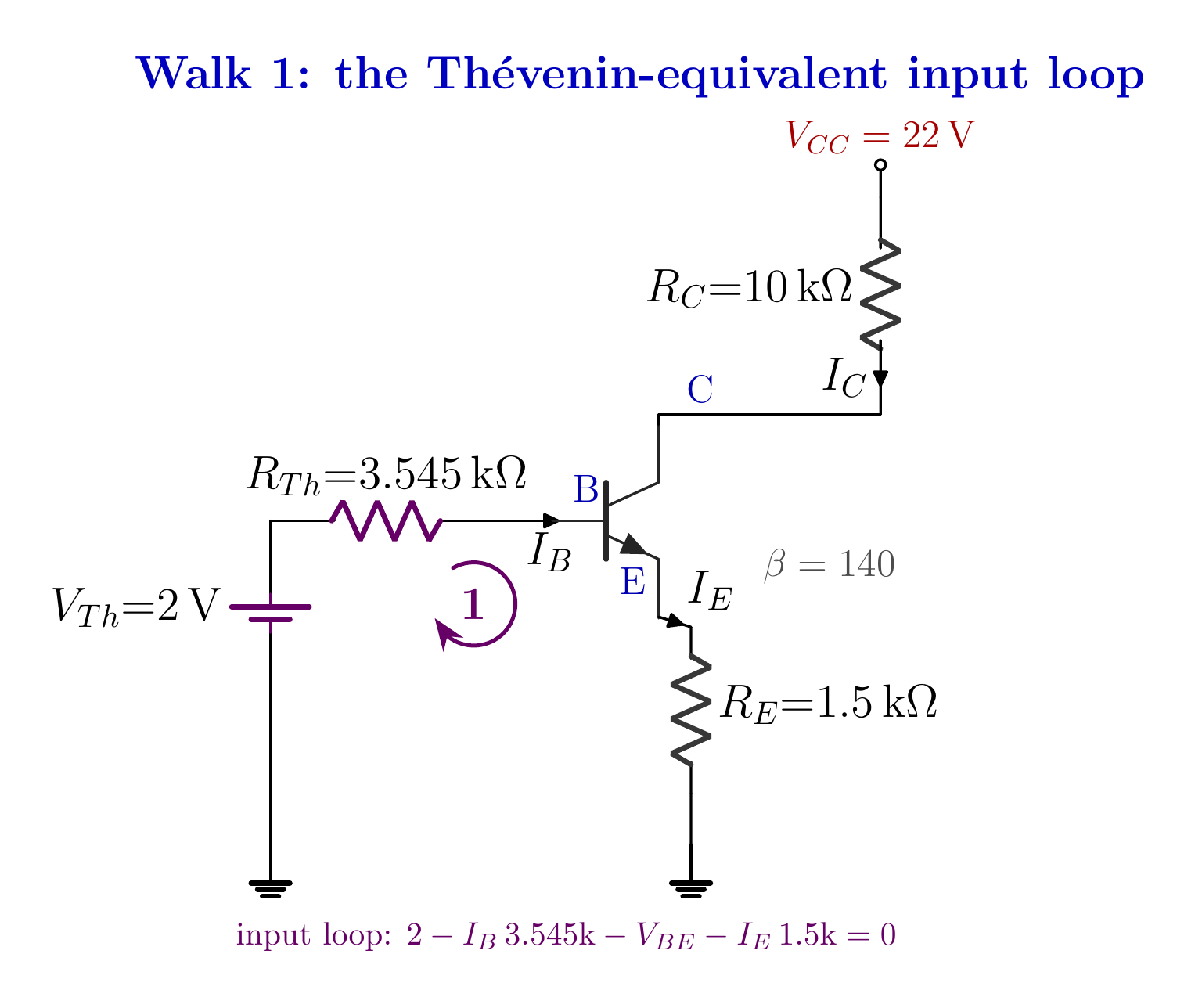
The Thevenin equivalent reduces the base loop to one source and one series resistance. Magnitude: base current is in microampsNarration transcript
Redraw it, and look how friendly it became. A two volt source, through 3.545 kilo-ohms, into the base. Emitter through 1.5 kilo-ohms to ground. This is the emitter-bias circuit from last time, wearing new numbers. So we walk it with Kirchhoff, exactly as before. Start at the Thevenin source, two volts. Pay the toll across the Thevenin resistor: minus I sub B times 3.545 k. Step across the base-emitter junction: minus 0.7. And down through the emitter resistor. Carrying which current? Not I sub B. We learned that trap last time. It carries the emitter current, beta plus one times I sub B, and beta plus one is one hundred forty-one. So that toll is minus one hundred forty-one I sub B times 1.5 k. And we land on ground, zero. Now collect the pieces. Two minus 0.7 is 1.3. One hundred forty-one times 1.5 k is 211.5 k. There is the giant shadow again: a small emitter resistor, seen from the base, multiplied a hundred and forty-one fold. Add the 3.545 k in front of it: 215.045 k in total. So I sub B is 1.3 volts over 215.045 k. Volts over ohms gives amps: 6.045 microamps. Magnitude check: base currents live in microamps. Six is on the small side, and that is simply the large beta doing its work. Perfectly healthy.
6. Transistor currents
The base loads the divider, so the exact solution uses a Thevenin equivalent. IC ≈ 0.846 mAIE ≈ 0.852 mANarration transcript
With I sub B on the board, the currents tumble out. The collector current is beta times I sub B: one hundred forty times 6.045 microamps, which is 846.3 microamps. Slide the decimal three places: 0.846 milliamps. The emitter current is beta plus one times I sub B: one hundred forty-one times 6.045, which is 852.4 microamps, so 0.852 milliamps. Magnitude check: collector currents live in milliamps, and we landed just under one. Perfectly reasonable. And the old promise holds again. 846 against 852: practically twins. I sub C is approximately I sub E.
7. Output loop
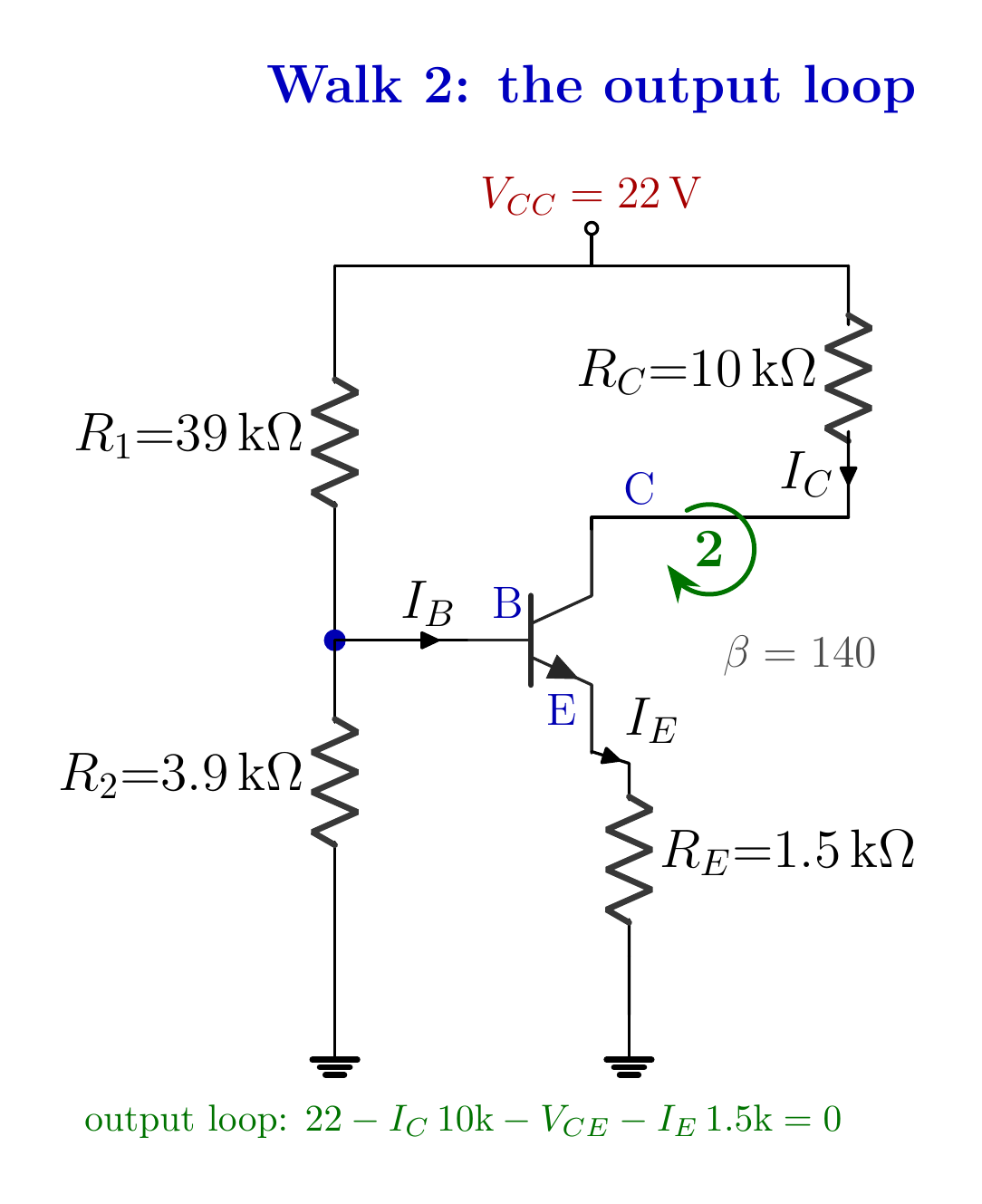
The output KVL loop determines V_CE and closes the supply-voltage check. Narration transcript
The last walk runs down the collector side of the original circuit. The real one, not the equivalent. Remember, the equivalent was only ever a stand-in for the base's point of view. Start at twenty-two volts. Down through R sub C, ten kilo-ohms, carrying I sub C. Ten times 0.846 is 8.46 volts gone. Across the transistor: minus V sub C E, our unknown. Down through R sub E, carrying I sub E: 1.5 times 0.852 is about 1.28 volts. And we reach ground. Gather it up. V sub C E is twenty-two, minus 8.46, minus 1.28. That is 12.26 volts. And that is the answer the problem asked for: about twelve volts across the transistor, with 0.846 milliamps through it. Three quick bonuses, since we already paid for them. The emitter sits at 1.28 volts. The collector sits at twenty-two minus 8.46: 13.54 volts. And the base sits one junction above the emitter: 0.7 plus 1.28, which is 1.98 volts. Pause on that last one, because it is quietly beautiful. The divider promised two volts. With the transistor connected and drawing its current, the base sits at 1.98. The ladder sagged by twenty-one millivolts. Remember the river? Half a milliamp pours down the divider, while the base sips six microamps through a straw. Eighty-five times less. A sip does not move a river. And the final sanity check: 8.46 plus 12.26 plus 1.28 is twenty-two volts exactly. Nothing leaked.
8. β stability test
The base loads the divider, so the exact solution uses a Thevenin equivalent. β = 70 → IC ≈ 0.827 mAβ = 140 → IC ≈ 0.846 mAβ = 280 → IC ≈ 0.856 mAFourfold β; only about 3.5% current spanThe divider holds VB; RE holds currentStable operating pointNarration transcript
Now the payoff. The experiment I promised at the start. We are going to be cruel to this circuit. Take our transistor, beta one hundred forty, and rip it out. First, drop in a weak one: beta seventy. Half the gain. Watch the fixed-bias circuit on the left, the one from two lessons ago, set up at the same operating point. Its collector current is chained directly to beta, so it crashes to half: from 0.85 down to 0.42 milliamps. Minus fifty percent. Any amplifier built around it is now badly off center. And our voltage-divider circuit? 0.827 milliamps. It moved by about two percent. Now the other direction. Drop in a hot transistor: beta two hundred eighty. Double the original, four times the weak one. Fixed-bias doubles: 1.69 milliamps, and its V sub C E collapses toward five volts, sliding toward saturation, the edge of clipping. Ours? 0.856 milliamps. One percent up. Four-fold beta. One percent of motion. Why? Look at the bottom of our base current fraction. Three and a half k from the divider, plus over two hundred k from the reflected emitter resistor. Beta dominates the top and the bottom of that fraction at the same time, so it nearly cancels itself out of the answer. The divider holds the base voltage steady. The emitter resistor turns that steady voltage into a steady current. The transistor's own personality has almost nothing left to say. And that is why this is the bias circuit you find in real schematics. You can buy a bag of transistors with betas scattered from seventy to nearly three hundred, solder in any one of them, and every single board lands on the same operating point.
9. Method summary
The base loads the divider, so the exact solution uses a Thevenin equivalent. 2) VTh = unloaded divider voltage3) Base KVL → IB4) Find IC and IE5) Output KVL → VCEIC ≈ 0.846 mA; VCE ≈ 12.26 VNext: the stiff-divider approximationNarration transcript
Let us fold this into your pocket. The circuit: a voltage divider holds the base, an emitter resistor holds the current. The method: when the base looks into something complicated, collapse it with two short experiments. Kill the source and merge what you see: that is the Thevenin resistance. Open the terminal and read the resting voltage: that is the Thevenin voltage. After that, it became last lesson's problem, and the same two Kirchhoff walks finished it: six microamps into the base, 0.85 milliamps through the collector, about twelve volts across the transistor. And an operating point that just shrugs when beta quadruples. One more thing before you go. Half a milliamp down the ladder, against six microamps into the base. Eighty-five to one. That ratio is begging for a shortcut. If the sip is that tiny, why not ignore it completely, call the base two volts, and skip Thevenin altogether? That is exactly the approximate method. It takes three lines, and it lands within two percent of everything we computed today. Next lesson, we earn the right to be lazy. See you there.
Source video: Electronics Basics #17 | BJT Voltage-Divider Bias: Exact Thevenin Analysis Step by Step (13:35)