Electronics 1 · Electronics Basics
#18 BJT voltage-divider bias — stiff-divider approximation
Verify the stiff-divider criterion, neglect base current, solve the BJT operating point in three short steps, and compare it with the exact result.
Question
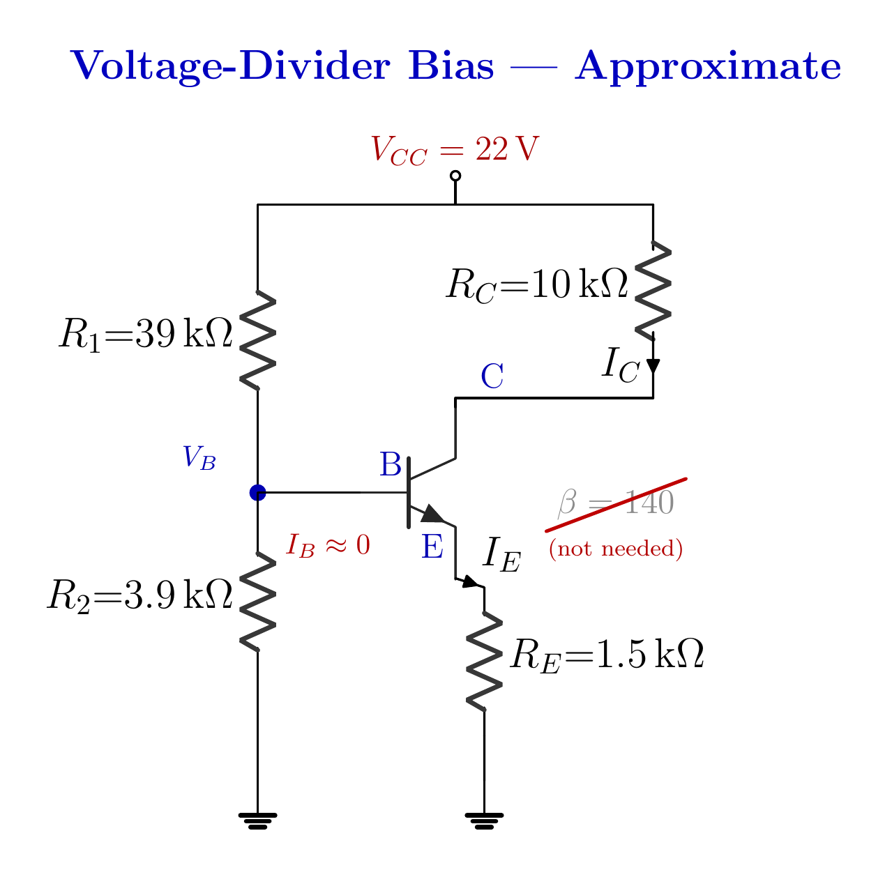
For the NPN voltage-divider bias circuit with V_CC = 22 V, R_1 = 39 kΩ, R_2 = 3.9 kΩ, R_C = 10 kΩ, R_E = 1.5 kΩ, and β = 140, test the stiff-divider criterion. Use the approximate method to find V_B, I_C, and V_CE, then compare the error with the preceding exact solution.
Written solution and narration transcript(shows the full solution)
Below are all the lines written in the notebook together with the full narration transcript.
1. From exact to quick
When the stiff-divider criterion passes, β leaves the calculation and the unloaded divider sets the base voltage. Previous exact result:Divider current ≈ 0.5128 mAIdiv / IB ≈ 85Base current barely loads the dividerCheck the criterion before taking the shortcutNarration transcript
Welcome back. Last time we solved the voltage-divider bias circuit the honest way, the exact way, with Thevenin. And we ended on a striking number. Half a milliamp poured down the divider ladder, while the base sipped only six microamps through it. Eighty-five to one. A sip that small does not move a river. Today we cash that in. If the base current is truly negligible, why carry it at all? Drop it, and the whole Thevenin detour collapses into three short lines. But there is a condition, and an engineer always checks the condition before taking the shortcut. So let us start there.
2. Stiff-divider criterion
When the stiff-divider criterion passes, β leaves the calculation and the unloaded divider sets the base voltage. Stiff-divider criterion210 kΩ ≥ 39 kΩ → criterion passesApproximation:Narration transcript
Here is the same circuit, and here is the question we must ask first: is the divider stiff enough? Think about what holds the base voltage. The divider tries to fix it at one value; the transistor leg, pulling current through the emitter, tries to load it down. The emitter resistor, seen from the base, looks like beta plus one times R sub E, the reflected resistance we met last time. The base node stays firm only if that reflected resistance is much bigger than the lower divider resistor R two. The standard rule of thumb: beta times R sub E should be at least ten times R two. Let us test it. Beta times R sub E is one hundred forty times 1.5 k, which is two hundred ten k. Ten times R two is ten times 3.9 k, which is thirty-nine k. Two hundred ten k is comfortably bigger than thirty-nine k, more than five times over. The divider is stiff. The criterion passes, so we are cleared to ignore the base current. Everything that follows rides on this one green light.
3. Find V_B in one line
When the stiff-divider criterion passes, β leaves the calculation and the unloaded divider sets the base voltage. Treat the divider as unloadedIdiv = 22/(39 kΩ + 3.9 kΩ)Idiv = 0.5128 mAVB = Idiv R2Narration transcript
Step one: the base voltage, in a single line. Because we are now treating the base current as zero, no current branches off into the transistor. The divider is unloaded. So the same current flows straight down through R one and R two, and the base just reads the voltage at their junction. That is the plain voltage-divider rule you have known since the very first resistor lesson. The current down the ladder is the supply over the total resistance: twenty-two volts over forty-two point nine k, which is 0.5128 milliamps. The base sits at that current times R two: 0.5128 times 3.9 k, which is almost exactly two volts. V sub B equals two volts. No Thevenin equivalent, no base loop, no reflected resistance. One divider, one line.
4. I_C and the missing β
When the stiff-divider criterion passes, β leaves the calculation and the unloaded divider sets the base voltage. IE = 1.30/1.5 kΩ ≈ 0.867 mAIC ≈ IE ≈ 0.867 mAβ never enters the calculationNarration transcript
Step two: the collector current, and watch what is missing. We know the base sits at two volts. Cross the base-emitter junction, drop the usual 0.7, and the emitter sits at two minus 0.7, which is 1.3 volts. That voltage sits across the emitter resistor, and Ohm's law hands us the emitter current directly: 1.3 volts over 1.5 k, which is 0.867 milliamps. And as always, the collector current is essentially the same: I sub C is approximately 0.867 milliamps. Now look back at what we just did, and notice what never appeared. Beta. We never used it. Not once. In the exact method, beta sat in the denominator and nudged the answer a little. Here it is gone completely. The base voltage is set by two resistors and the supply; the current is set by that voltage and the emitter resistor. The transistor's gain has no say at all. Swap in a part with beta fifty, or beta three hundred, and this circuit lands on the very same operating point. That is why the source crossed beta out.
5. Output loop
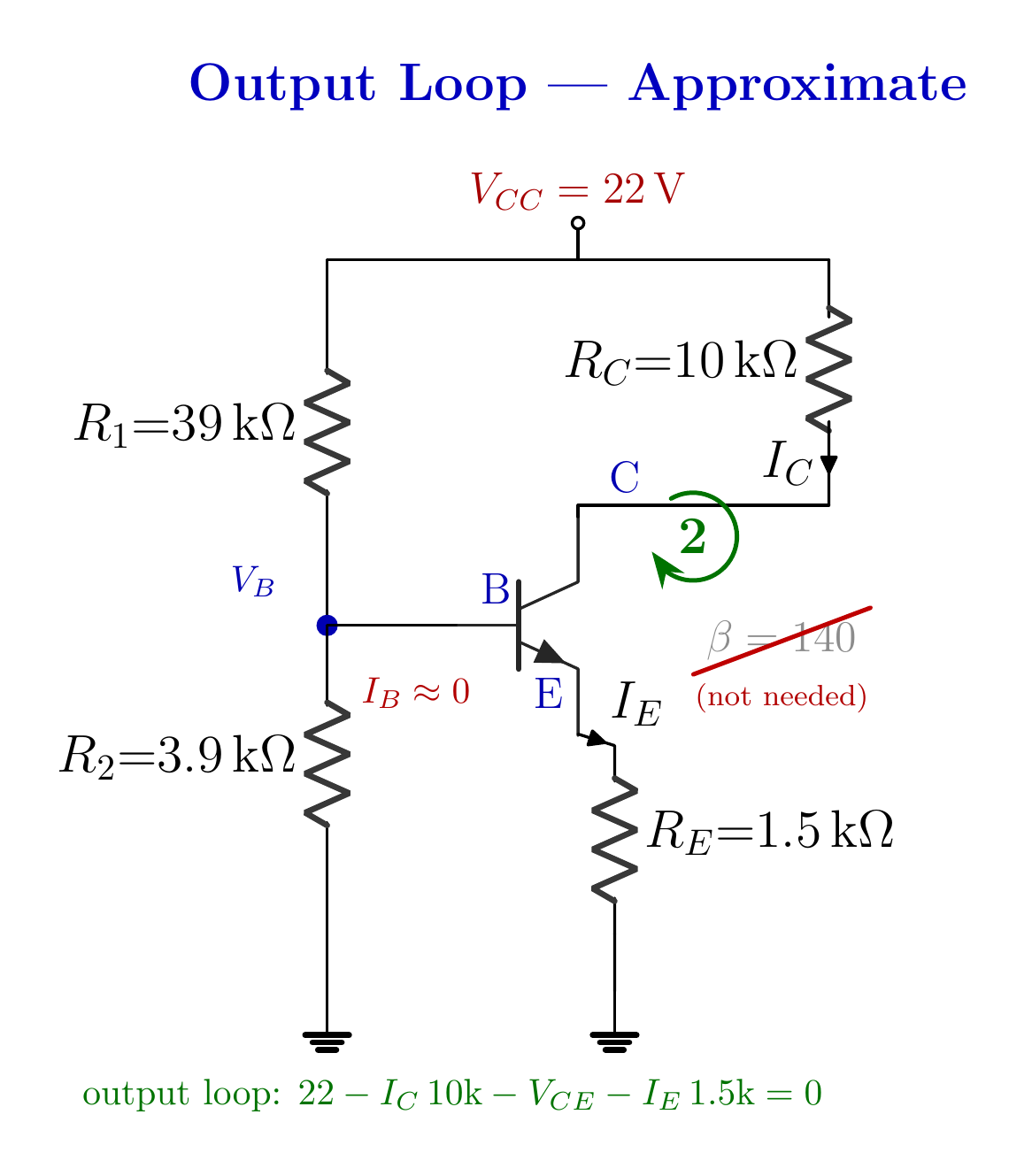
The output loop finds V_CE from the drops across R_C and R_E. VRC ≈ 0.867 mA·10 kΩ = 8.67 VVRE ≈ 0.867 mA·1.5 kΩ = 1.30 VNarration transcript
Step three: the collector-emitter voltage, the last unknown. Walk the output loop, exactly as before. Start at twenty-two volts, down through R sub C carrying I sub C, across the transistor, and down through R sub E carrying I sub E. The collector resistor drops ten k times 0.867 milliamps, which is 8.67 volts. The emitter resistor drops 1.5 k times 0.867 milliamps, which is 1.3 volts. So V sub C E is twenty-two, minus 8.67, minus 1.3, which is 12.03 volts. Quick sanity check: the three drops should rebuild the supply. 8.67 plus 12.03 plus 1.3 is twenty-two volts, exactly. Nothing leaked. Three lines, and the circuit is solved.
6. Exact versus approximate
When the stiff-divider criterion passes, β leaves the calculation and the unloaded divider sets the base voltage. Exact ↔ approximateVB: 1.98 V ↔ 2.00 VIC: 0.846 mA ↔ 0.867 mAVCE: 12.26 V ↔ 12.03 VErrors ≈ 1–2.5%When the criterion passes, the shortcut is reliableNarration transcript
Now the moment of truth. Was the shortcut honest? Let us lay today's approximate answers beside last time's exact ones, side by side. The base voltage: exact gave 1.98 volts, approximate gave 2.00. The collector current: exact 0.846 milliamps, approximate 0.867. The collector-emitter voltage: exact 12.26 volts, approximate 12.03. Every pair agrees to within about two percent. Two percent, for a method that skipped an entire Thevenin construction and never touched beta. That is the engineer's bargain. When the divider is stiff, the exact answer and the quick answer are practically the same number, so you take the quick one. If the criterion had failed, if the divider were soft, the gap would widen and you would go back to the exact method. The criterion is what tells you which world you are in.
7. Method summary
When the stiff-divider criterion passes, β leaves the calculation and the unloaded divider sets the base voltage. 1) Check βRE ≥ 10R22) Find VB from the unloaded divider5) Output KVL → VCEIC ≈ 0.867 mA; VCE ≈ 12.03 VNarration transcript
Let us pocket it. The approximate voltage-divider method is three lines. Check the criterion: beta R sub E at least ten times R two. If it passes, ignore the base current; the base voltage is just the divider, two volts here. Subtract 0.7 for the junction, divide by the emitter resistor, and you have the current, 0.867 milliamps. One output loop gives the collector-emitter voltage, 12.03 volts. And the headline you carry forward: in a stiff divider, the operating point does not depend on beta at all. That is the whole reason this is the bias circuit real designs reach for. You solder in any transistor from the bin, and every board lands on the same point. With this, our DC analysis of the BJT is complete: fixed-bias, emitter-bias, and now voltage-divider bias, exact and approximate. Next, we meet a different kind of transistor, the field-effect transistor, where a voltage, not a current, is in command. See you there.
Source video: Electronics Basics #18 | BJT Voltage-Divider Bias: The Approximate Method (7:30)