Circuit Theory 1 · Energy Storage and Transients
#39 Transient Analysis #39 — Capacitor/inductor combinations and initial conditions
Explains capacitor and uncoupled-inductor equivalents, division rules, continuity principles, and the three-step switching method through two numerical examples.
Question
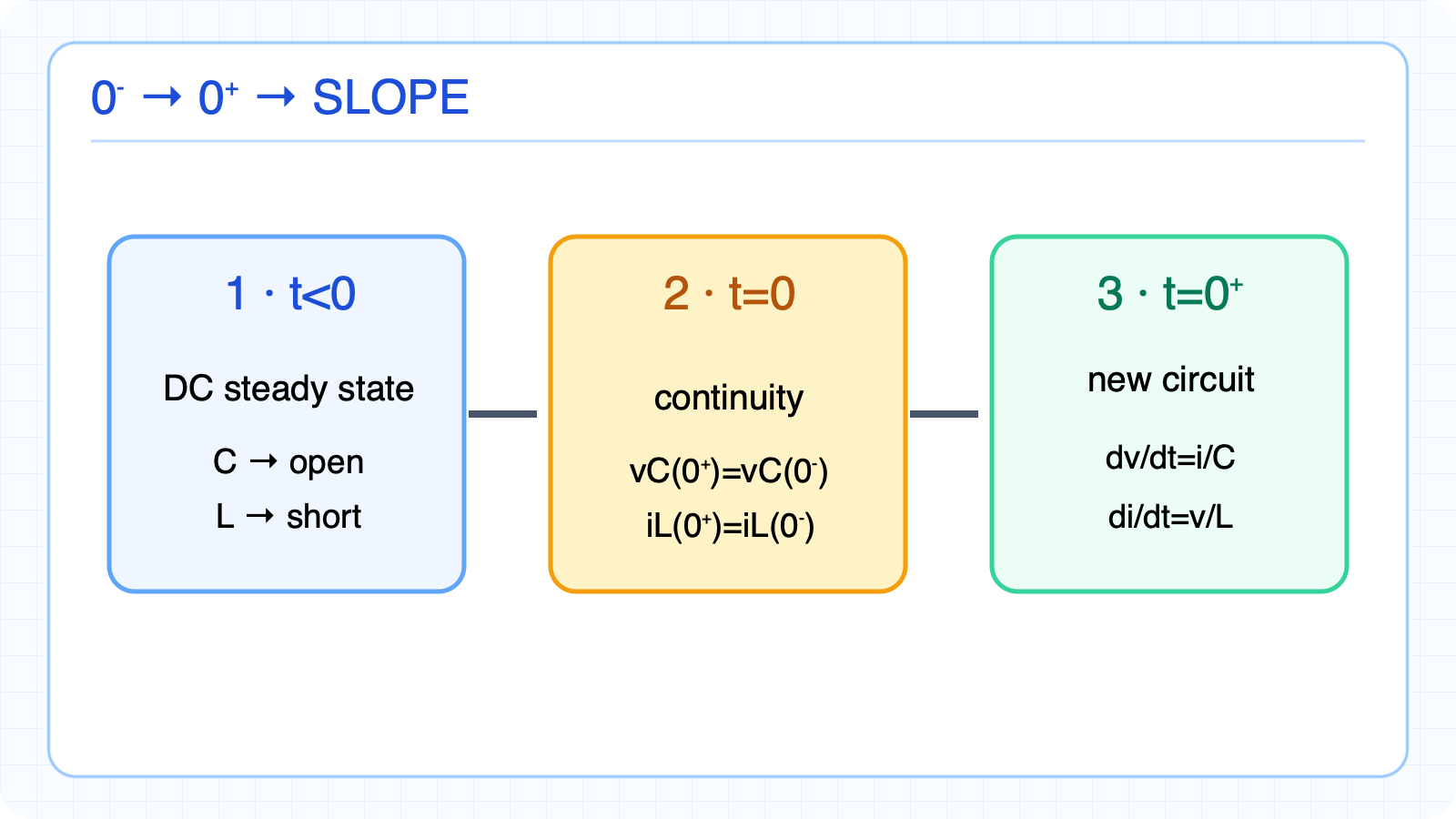
Derive series/parallel equivalents for C and uncoupled L; explain capacitor division rules; use v_C and i_L continuity to find the 0+ values and initial slopes of RC and RL circuits.
Written solution and narration transcript(shows the full solution)
Below are all the lines written in the notebook together with the full narration transcript.
1. Series and parallel capacitors
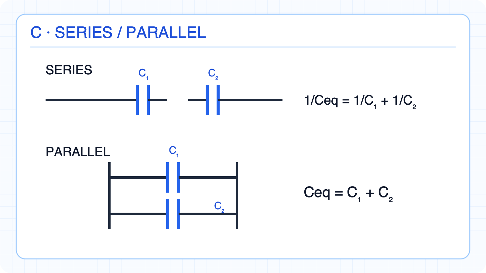
Use reciprocal sum in series and direct sum in parallel. Ideal capacitor equivalentsSeries: the same charge qTwo elements:Parallel: the same voltage vCapacitor rules are opposite to resistor rulesNarration transcript
When capacitors are connected in series, the equivalent capacitance is the reciprocal sum. One over C-eq equals one over C-one plus one over C-two — just like resistors in parallel. For two capacitors: C-eq equals C-one times C-two, divided by C-one plus C-two. When capacitors are in parallel, the equivalent capacitance is simply the sum: C-one plus C-two. This is opposite to resistors: series capacitors combine like parallel resistors, and parallel capacitors combine like series resistors.
2. Capacitor voltage and current division
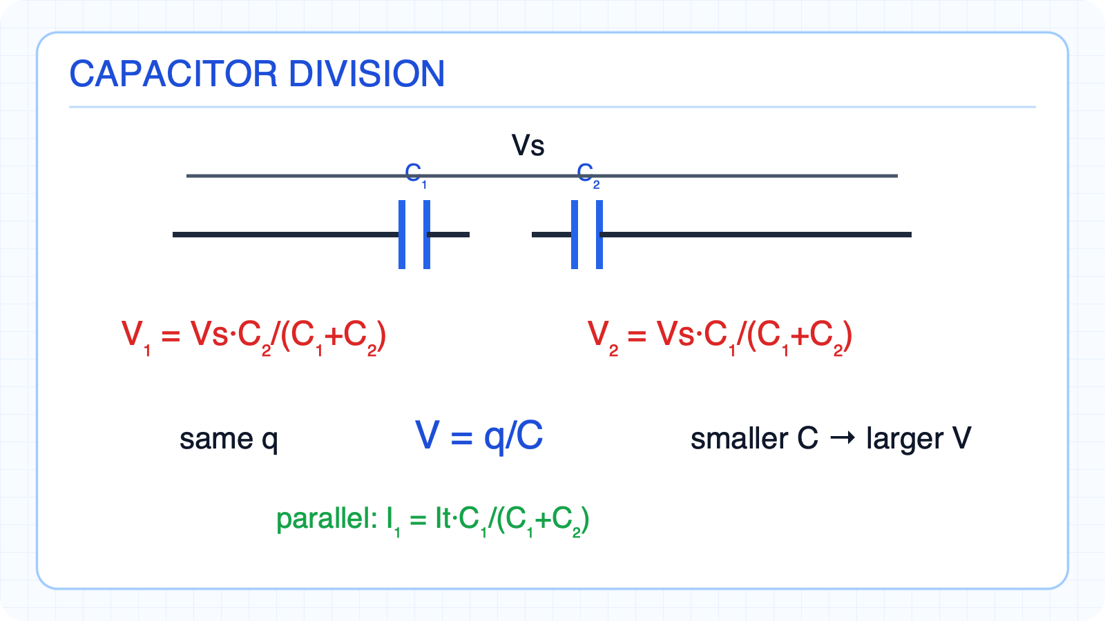
The smaller series capacitor carries the larger voltage. Equal charge in series; equal voltage in parallelSeries: V1=q/C1 and V2=q/C2The smaller C carries the larger voltageParallel: ik=Ck·dv/dtThe larger C carries the larger currentNarration transcript
Voltage division with series capacitors has a surprising twist. V-one equals V-source times C-two over C-one plus C-two — notice it's the OTHER capacitor in the numerator. This is the INVERSE of resistor voltage division. The smaller capacitor gets MORE voltage, because it stores the same charge but with less capacitance. Current division in parallel capacitors is direct: I-one equals I-total times C-one over C-one plus C-two. The larger capacitor carries more current — this makes sense since I equals C times d-V-d-t, and both capacitors share the same voltage.
3. Series and parallel inductors
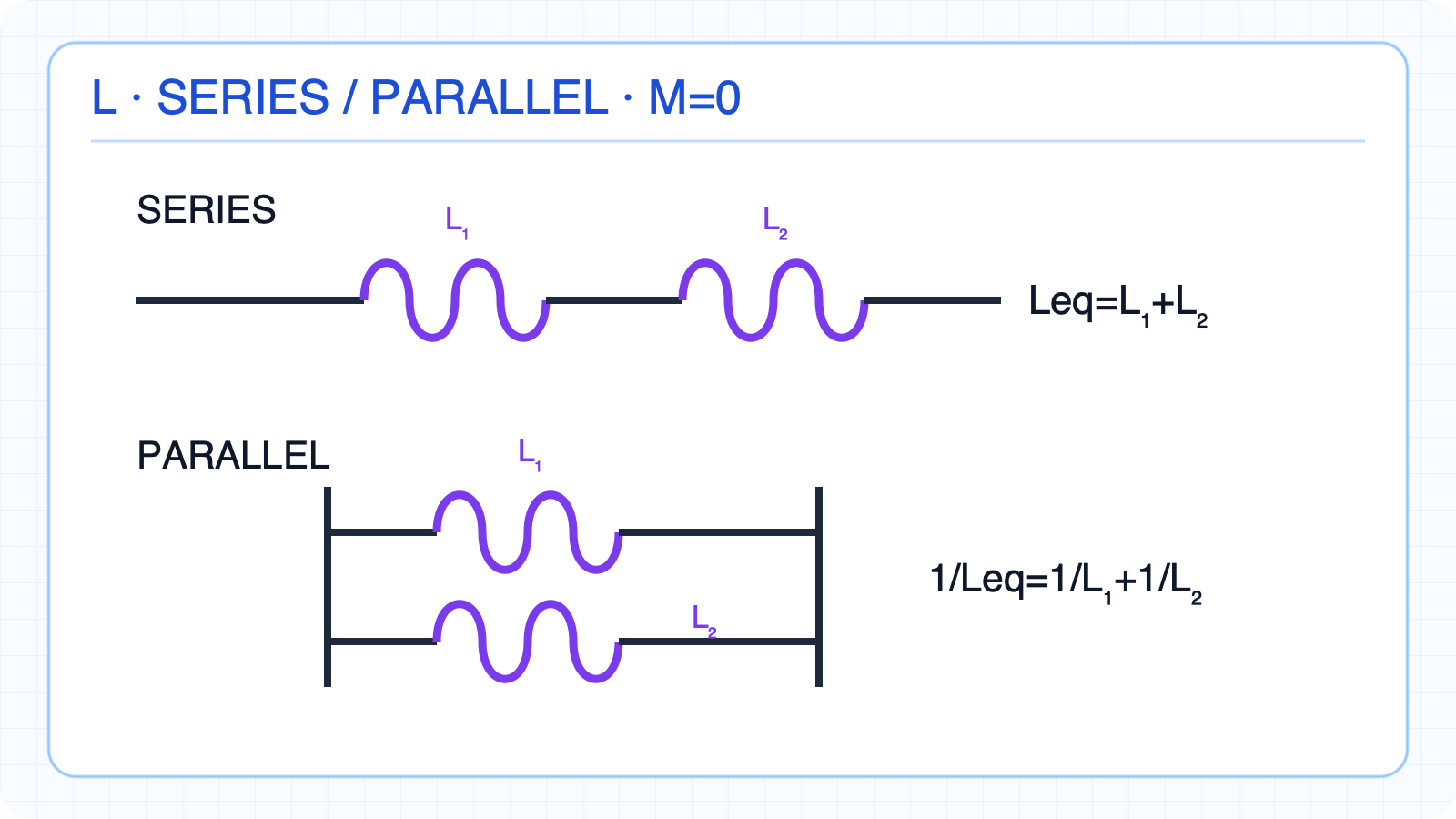
Use direct sum in series and reciprocal sum in parallel. Ideal, magnetically uncoupled inductors:Series:The same current flows in seriesThe same voltage appears in parallelTwo elements:Magnetic coupling introduces mutual inductance termsNarration transcript
Inductors combine exactly like resistors. Series inductors add directly: L-eq equals L-one plus L-two. Parallel inductors use the reciprocal formula: one over L-eq equals one over L-one plus one over L-two. This is the exact dual of capacitors — swap series and parallel, and you swap the C and L combination rules. Series inductors are simple addition, just like series resistors.
4. Capacitor–inductor combination duality
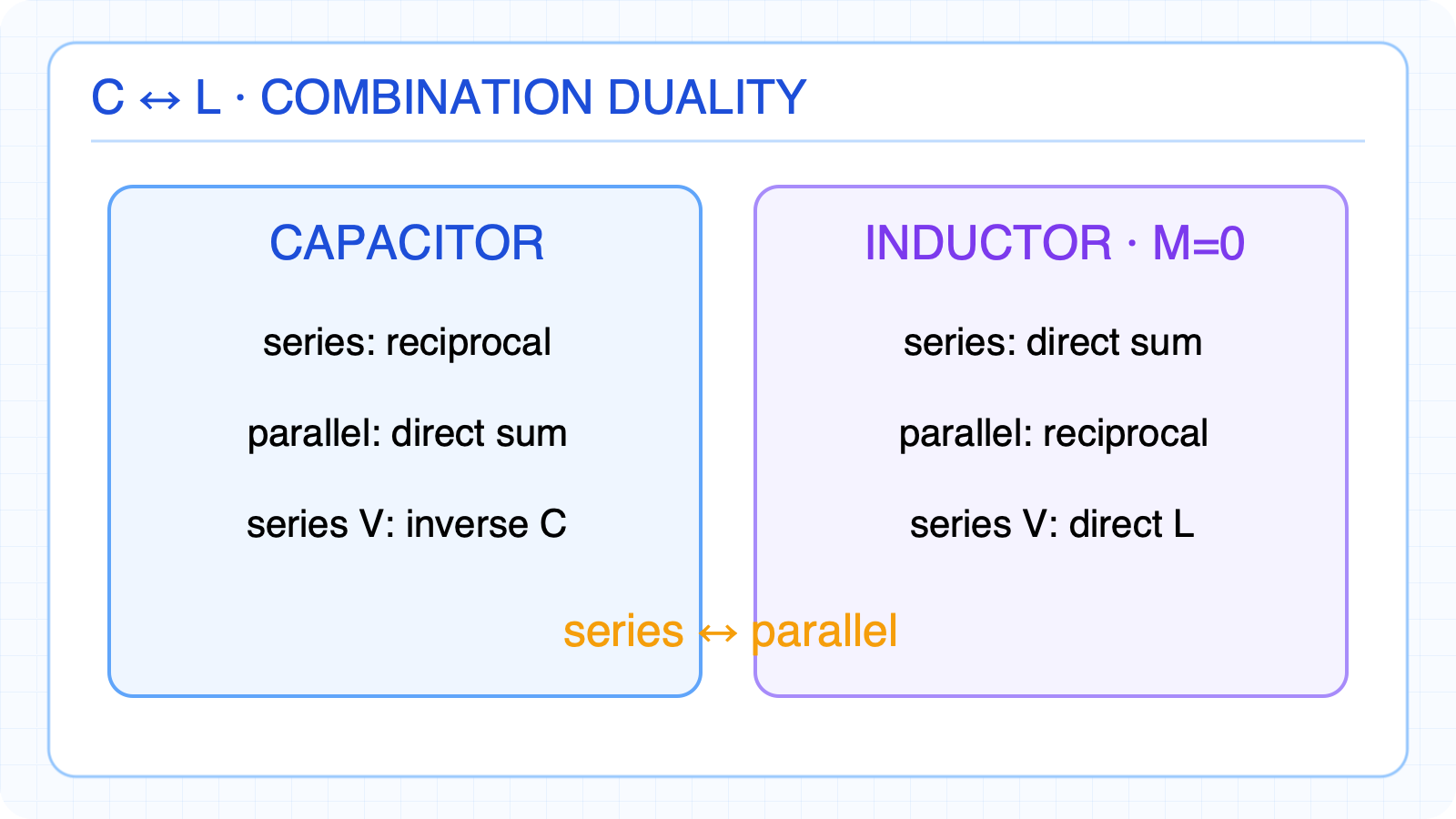
Series-parallel and direct-reciprocal rules are compared. Compare C and L combination rulesSeries C: reciprocal sumSeries L: direct sum for M=0Parallel C: direct sumParallel L: reciprocal sum for M=0Series-capacitor voltage divides inverselySeries ↔ parallel and C ↔ L dualityNarration transcript
Let's compare capacitor and inductor combination rules side by side. Series capacitors use reciprocal sum, but series inductors add directly. Parallel capacitors add directly, but parallel inductors use reciprocal sum. Voltage divides inversely with capacitors, but directly with inductors. This beautiful duality extends to everything we've seen about C and L — it's a fundamental symmetry in circuit theory.
5. Continuity at switching
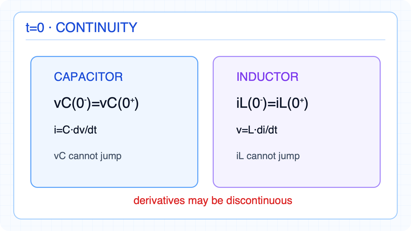
v_C and i_L cannot jump, while their derivatives may be discontinuous. Energy-storage state variables cannot jumpA jump in vC requires infinite current through i=C·dv/dtA jump in iL requires infinite voltage through v=L·di/dtiC and vL may jumpdvC/dt and diL/dt may be discontinuousNarration transcript
The most fundamental rules for circuit transient analysis. Capacitor voltage cannot change instantaneously: V-C at zero-minus equals V-C at zero-plus. Why? Because an instantaneous voltage change would require infinite current: I equals C times d-V-d-t. Similarly, inductor current cannot change instantaneously: I-L at zero-minus equals I-L at zero-plus. An instantaneous current change would require infinite voltage: V equals L times d-I-d-t. However, the DERIVATIVES d-V-d-t and d-I-d-t CAN be discontinuous at t equals zero.
6. Three-step switching method
Solve the DC pre-state, apply continuity, then solve the new 0+ circuit. Find initial conditions systematically1) Solve the t<0 circuit in DC steady stateAt DC, C is open and L is shortFind vC(0⁻) and iL(0⁻)2) Carry values to 0+ by continuity3) Solve the new t=0+ circuitdvC/dt=iC/C and diL/dt=vL/LNarration transcript
Here is the three-step method for analyzing switch circuits. Step one: Analyze the circuit for t less than zero. Find the DC steady state. In DC steady state, capacitors are open circuits and inductors are short circuits. This gives you V-C at zero-minus and I-L at zero-minus. Step two: Apply the continuity rules. V-C at zero-plus equals V-C at zero-minus. I-L at zero-plus equals I-L at zero-minus. Step three: Analyze the NEW circuit at t equals zero-plus, using V-C and I-L as known initial values. Calculate d-V-d-t at zero-plus equals I at zero-plus divided by C, and d-I-d-t at zero-plus equals V at zero-plus divided by L. This three-step method is the foundation for all transient analysis.
7. RC switching example
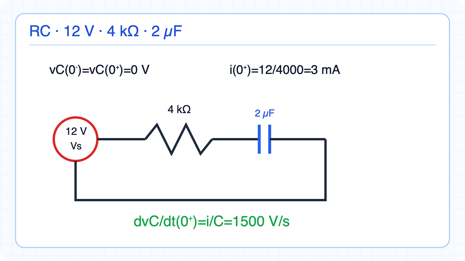
Initial current is 3 mA and voltage slope is 1500 V/s. The switch closes at t=0; capacitor initially unchargedAt t=0+, all 12 V is across the resistori(0⁺)=3 mAdvC/dt(0⁺)=3 mA/2 µF=1500 V/sNarration transcript
Let's apply our method to a simple RC circuit. A 12 volt source in series with a 4 kilohm resistor and a 2 microfarad capacitor. The switch closes at t equals zero. Before that, no current flows, so V-C at zero-minus equals zero. Step two: V-C at zero-plus equals V-C at zero-minus equals zero volts. Step three: At t equals zero-plus, the capacitor voltage is zero, so all 12 volts appear across the resistor. I at zero-plus equals 12 over 4000 equals 3 milliamps. The initial rate of voltage change: d-V-d-t at zero-plus equals I over C equals 3 milliamps over 2 microfarads equals 1500 volts per second. These initial conditions are everything we need to write the complete transient response.
8. RL switching example
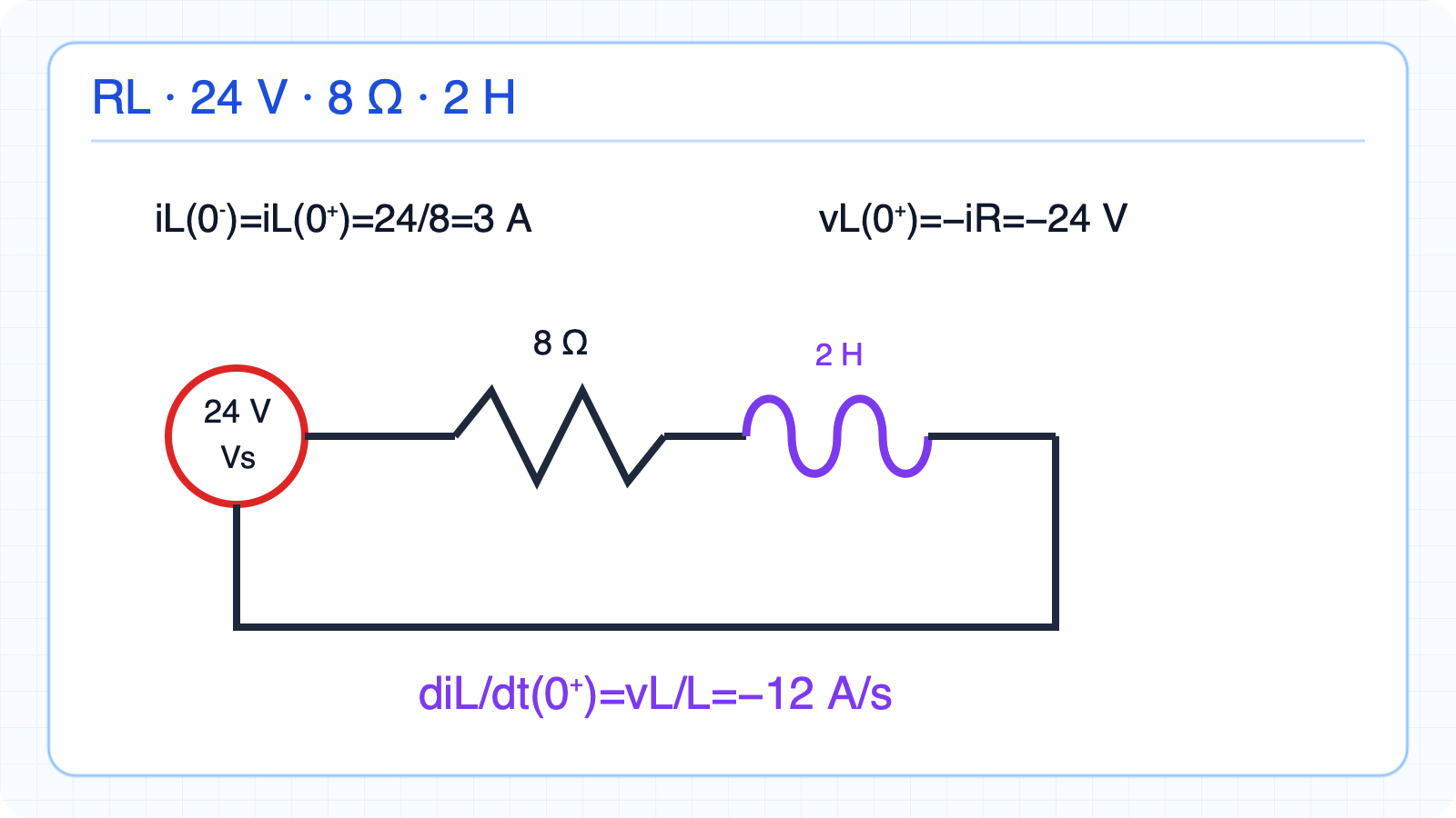
Initial current is 3 A, inductor voltage −24 V, and slope −12 A/s. Switch long closed: L is a shortAfter source removal, current continues through RvL(0⁺)=−iR=−24 VdiL/dt(0⁺)=vL/LdiL/dt(0⁺)=−12 A/sNarration transcript
Now an RL circuit with opposite behavior. A 24 volt source, 8 ohm resistor, and 2 henry inductor. The switch has been closed for a long time, so the inductor is a short circuit. I-L at zero-minus equals 24 over 8 equals 3 amps. At t equals zero, the switch opens, disconnecting the voltage source. Step two: I-L at zero-plus equals I-L at zero-minus equals 3 amps — the current must continue flowing. Step three: At t equals zero-plus, the 3 amp current flows through the resistor, creating a voltage drop. V-L at zero-plus equals minus I times R equals minus 24 volts. The initial rate of current change: d-I-d-t at zero-plus equals V-L over L equals minus 24 over 2 equals minus 12 amps per second. The negative sign tells us the current is decreasing — the inductor is de-energizing.
9. Combinations and initial conditions summary
Solve the DC pre-state, apply continuity, then solve the new 0+ circuit. Preparing for transient analysisSeries C and parallel L: reciprocal sumParallel C and series L: direct sumvC and iL are continuous at switchingFirst solve the 0⁻ DC steady stateThen apply continuity and solve the 0+ circuitCorrect initial conditions anchor the full transient responseNarration transcript
Four key results from this lecture. First: series capacitors use reciprocal sum, parallel capacitors add directly — opposite to resistors. Second: capacitor voltage division is INVERSE — the smaller capacitor gets more voltage. Third: the continuity rules — capacitor voltage and inductor current cannot jump at t equals zero. Fourth: the three-step switch analysis method — find DC steady state, apply continuity, then analyze the new circuit. These initial condition skills are essential for the next lecture, where we solve the RC natural response — our first complete transient solution.