Circuit Theory II · Balanced Y–Y connection
#11 Circuit Theory-2 #11 | Y-Y Connection and Line-Phase Relations
Corrected solution notes. The audio is the original recording and may contain errors or incomplete phrases. Where they differ, use the corrected written solution.
Question
Corrected solution notes. The audio is the original recording and may contain errors or incomplete phrases. Where they differ, use the corrected written solution. Circuit Theory-2 #11 | Y-Y Connection and Line-Phase Relations
Written solution and narration transcript(shows the full solution)
Below are all the lines written in the notebook together with the full narration transcript.
1. Balanced Y–Y connection
Corrected solution notes. The audio is the original recording and may contain errors or incomplete phrases. Where they differ, use the corrected written solution.Connect a balanced positive-sequence source to equal Y load impedances.Use RMS phasors, ideal conductors and consistent source/load neutral references.Narration transcript
In the previous lesson we saw that a balanced three-phase set is three equal vectors, spaced one hundred twenty degrees apart, summing to zero. That picture lives on a phasor diagram. Now we connect it to a real circuit. The most common topology is Y-to-Y: a Y source feeding a Y load. Once we draw it, two new questions appear naturally -- what is the voltage between two lines, and how does it relate to the voltage you measure to neutral?
2. Topology and names
Each phase impedance connects a line to the load neutral.Phase voltage is line-to-neutral; line voltage is measured between two lines. A neutral conductor connects the neutral nodes when included.Narration transcript
Here is the standard Y-Y connection. On the left, three sources Va, Vb, Vc share a common point n, the source neutral. On the right, three load impedances Z Y share their own common point N, the load neutral. Three conductors, called lines a, b, and c, carry power from source to load. A fourth wire connects the two neutrals -- that is the neutral line. The voltage measured from one line to neutral is called a phase voltage. The voltage measured between two lines is called a line voltage.
3. Phase phasors
Va=Vp∠0°, Vb=Vp∠−120°, Vc=Vp∠120°.Equal magnitudes and 120° spacing make their phasor sum zero.Narration transcript
In a positive sequence balanced set, the three phase voltages are written: Va equals V p at angle zero degrees, Vb equals V p at angle minus one hundred twenty degrees, and Vc equals V p at plus one hundred twenty degrees. Same magnitude V p. Same frequency. Spacing fixed at one hundred twenty degrees. This is exactly the symmetric set from the previous video -- now anchored to specific terminals on a real circuit.
4. Line voltage
Vab=Va−Vb.Likewise Vbc=Vb−Vc and Vca=Vc−Va. Preserve the terminal order in each subtraction.Narration transcript
The line voltage Vab is the voltage at terminal a measured with respect to terminal b. By Kirchhoff's voltage law, Vab equals the phase voltage Va minus the phase voltage Vb. So if we know the phase voltages, the line voltages drop out by simple subtraction. The question is -- what does that subtraction look like geometrically?
5. Correct phasor geometry
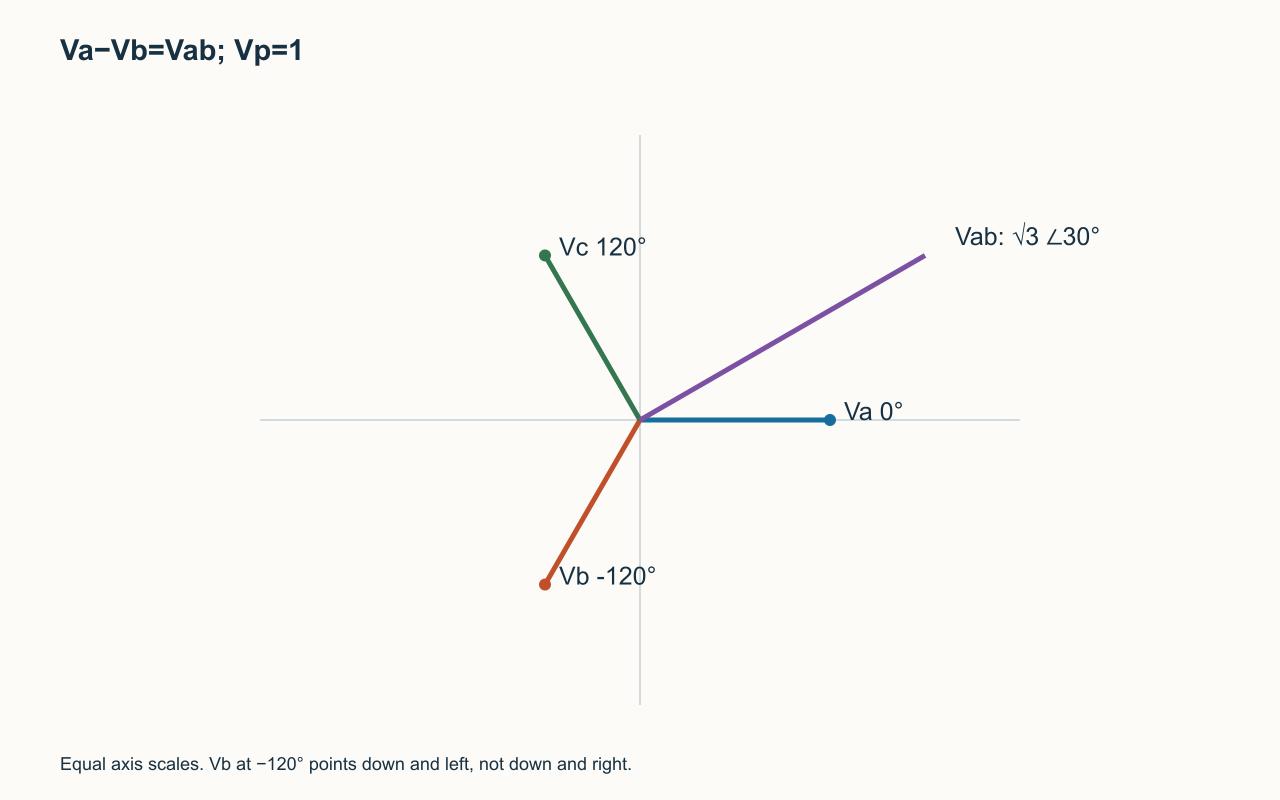
At −120°, Vb points down and left, with components (−Vp/2,−√3Vp/2).Negating it points at +60°. Adding to Va gives components (3Vp/2,√3Vp/2).Therefore Vab=√3Vp∠30°.Narration transcript
Watch the construction on the phasor plane. Start with Va along the reference axis. Vb sits at minus one hundred twenty degrees, pointing down and to the right. To form Vab equals Va minus Vb, we flip Vb to get its negative -- that swings it up to plus sixty degrees -- and add it tip to tail to Va. The two vectors form a rhombus, and the diagonal from the origin to the far corner is exactly Vab. Two equal sides of length V p meet at an internal angle of sixty degrees, so the diagonal length comes from the cosine rule: square root of three times V p. The diagonal lands at plus thirty degrees. Vab leads Va by thirty degrees, with magnitude root three V p.
6. Line-voltage result
The other line voltages have angles −90° and 150°, with the same magnitude √3Vp.For this positive sequence, each ordered line voltage leads its corresponding phase reference by 30°.Narration transcript
Here is the result you carry forward. The line voltage magnitude is square root of three times the phase voltage magnitude, about one point seven three two times larger. The line voltage leads the corresponding phase voltage by thirty degrees. The other two line voltages, Vbc and Vca, follow the same pattern -- same magnitude root three V p, each one rotated by another one hundred twenty degrees. Three line voltages form a second balanced star, larger and rotated thirty degrees from the phase star.
7. Y current
Each line feeds one phase branch, so its line current equals that phase current.Divide each phase voltage by the corresponding phase impedance.Narration transcript
Now look at current. In the Y connection, each phase impedance sits between one line terminal and the neutral. There is no branching -- the current leaving terminal a goes straight through impedance Z Y. That single conductor carries everything. So in a Y load, the line current equals the phase current. No square root of three here. This identity is purely geometric, free from any extra calculation.
8. Balanced power
Total complex power is three times the phase RMS voltage multiplied by conjugate phase current.Real power is 3VpIp cosθ=√3VLIL cosθ; reactive power replaces cosine by sine. θ is the load-impedance angle.Narration transcript
Each phase delivers an average power equal to V phase times I phase times cosine theta, where theta is the angle between phase voltage and phase current -- the impedance angle. With three balanced phases, the total average power is three V phase I phase cosine theta. We can rewrite this in line quantities. V phase equals V line over root three. I phase equals I line. Substituting and simplifying, the total power becomes root three times V line times I line times cosine theta. Same number, written two ways. The reactive and apparent powers follow the identical structure.
9. Numerical example
Vp=120 V and ZY=10+j5 Ω give Ia=9.6−j4.8 A, magnitude √115.2≈10.7331 A.VL=120√3≈207.8461 V; power factor 2/√5≈0.894427.Total real power is exactly 3456 W for these stated values; early rounding slightly changes the result.Narration transcript
Let us put numbers on it. Take a balanced Y source with phase voltage one hundred twenty volts r m s, positive sequence. Each leg of the Y load is Z Y equals ten plus j five ohms. First, the magnitude and angle of Z Y: the magnitude is square root of one hundred twenty five, which is eleven point one eight ohms. The angle is the arctangent of five over ten, which is twenty six point five seven degrees. Phase current: I phase equals V phase over Z Y, which is one hundred twenty divided by eleven point one eight, giving ten point seven three amperes r m s, lagging by twenty six point five seven degrees. Line current equals phase current, ten point seven three amperes. Line voltage equals root three times one hundred twenty, which is two hundred seven point eight five volts. Cosine of twenty six point five seven degrees is zero point eight nine four. Total power: root three times two hundred seven point eight five times ten point seven three times zero point eight nine four equals about three thousand four hundred fifty four watts, or three point four five kilowatts.
10. Neutral current
Equal balanced branch impedances produce three currents summing to zero, so neutral current is zero in this ideal case.Unbalance, harmonics or other nonideal conditions require a separate neutral analysis.Narration transcript
One more important consequence. In the balanced case, the three line currents Ia, Ib, Ic form a balanced set themselves, each rotated by one hundred twenty degrees. Their vector sum is zero, exactly like the voltages. So the current returning through the neutral wire is zero. An ideal balanced Y-Y system needs no neutral conductor at all -- the neutral simply rides along carrying no current.
11. Review
Corrected mathematical reference; use with the written derivation. Y connection: line voltage magnitude √3 times phase voltage; line current equals phase current.The −120° vector points down-left. Use exact phasors until the final rounding and retain the balanced-system assumptions.Narration transcript
Two key takeaways. In Y-Y, line voltage is root three times phase voltage and leads by thirty degrees, while line current equals phase current. Total power is root three V line I line cosine theta, or three V phase I phase cosine theta -- the same number in two languages. Next we look at delta connections, where the same square root of three factor reappears, but this time on the current side.
Source video: Circuit Theory-2 #11 | Y-Y Connection and Line-Phase Relations (7:38)