Control Theory · Block Diagrams: Gain, Integration and Signed Sums
#06 Draw equivalent signal-flow diagrams using constant gains, integrators and summing junctions
Read the three building blocks and express signed sums using one junction, a cascade or grouped operations.
Question
Work with the ideal continuous-time linear operations introduced in this lesson. A gain is a constant scalar; it can amplify, attenuate, invert a sign, or be zero. Its units must map input units to output units. An integrator represents an initial output plus a definite time integral from a shared initial time; its output units are input units times time. The compact indefinite-integral notation suppresses the integration constant. For the three gain-integrator arrangements, first compare zero initial states with the same lower limit and constant A. With nonzero states, match the output initial values: an integrator followed by gain A has output initial value A times its internal initial state. For A=0 that route cannot supply a nonzero output initial value without an additional initial-value term. Do not commute a time-varying coefficient through integration; linearity alone does not mean arbitrary linear operators commute. The labels 2.1, 2.2 and 2.3 refer to arrangements, not numerical quantities. Connect signal arrows to the intended block or junction when drawing; the source uses visible spacing around some symbol boundaries. These are signal-flow schematics, not electrical continuity diagrams. At a summing junction, arrows point toward it for inputs and away for the output. A minus on an input line applies to that complete incoming signal; an unmarked input in this lesson is positive. Put signs clearly beside the appropriate junction input in your own drawing, rather than relying on color. Add only compatible signal quantities and units. The letter c is the output in the simple examples but becomes an independent input in the four-input example; e is the latter output. For the four-input example, use positive a,b and negative c,d. The cascade forms a+b, subtracts c, then subtracts d. The grouped route forms a+b and c+d separately, then subtracts the entire second sum; its equation card is an algebraic reference for this stated construction. Subtracting a sum negates both terms. Initial conditions must be retained when differential equations are converted into integral form. These three blocks support the constant-coefficient linear differential-equation models under discussion; nonlinearities, delays and other operators may require additional blocks. The lesson introduces building blocks and an algebraic example; a full differential-equation realization is deferred to the next lesson. Equivalent algebra alone is not a claim of closed-loop stability or tracking performance.
Written solution and narration transcript(shows the full solution)
Below are all the lines written in the notebook together with the full narration transcript.
1. Introduce block diagrams
Arrows indicate signal-flow direction, and a minus beside an incoming signal negates that signal before summation. The plus inside a junction denotes summation of these signed inputs. Labels 2.1, 2.2 and 2.3 identify three arrangements, not equal decimal numbers. Integral relations use constant gains and a common initial-condition convention. The grouped construction uses the equation card as its algebraic reference. Introduce Control Theory, Lesson 6.Learn to draw block diagrams.Use diagrams to visualize and analyze control systems.Narration transcript
Welcome to lesson 6 of Control Theory. Today, we'll learn how to draw block diagrams. This is an essential skill for visualizing and analyzing control systems.
2. Follow four drawing steps
Arrows indicate signal-flow direction, and a minus beside an incoming signal negates that signal before summation. The plus inside a junction denotes summation of these signed inputs. Labels 2.1, 2.2 and 2.3 identify three arrangements, not equal decimal numbers. Integral relations use constant gains and a common initial-condition convention. The grouped construction uses the equation card as its algebraic reference. Follow four drawing steps.Identify the input and output.Write the differential equation with every derivative term.Convert to integral form, preserving initial conditions and isolating the output.Draw the corresponding signal-flow diagram.Identify the required building blocks.Narration transcript
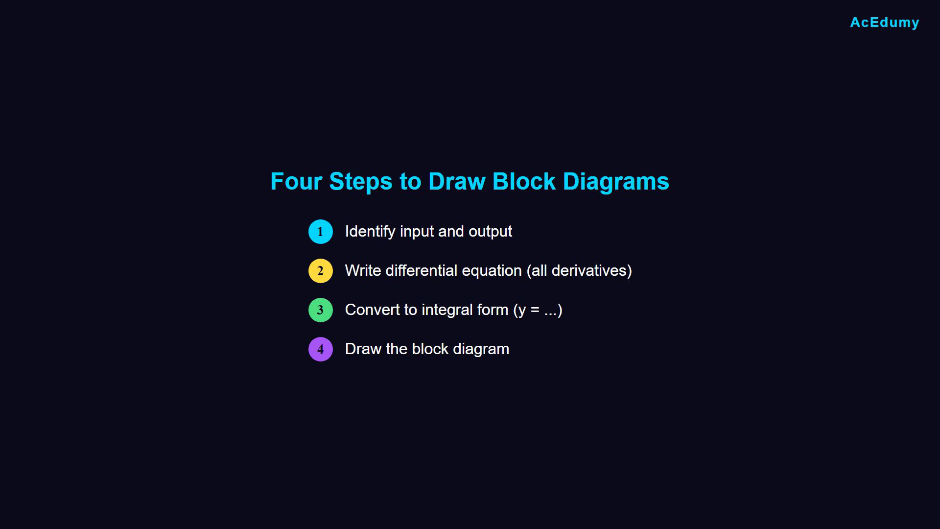
There are four main steps to draw a block diagram. Step 1: Identify the input and output. Step 2: Write the differential equation with all derivative terms. Step 3: Convert to integral form and write the equation starting with y equals. Step 4: Draw the block diagram based on this equation. Let's look at each building block we'll need.
3. Scale a signal with constant gain
Arrows indicate signal-flow direction, and a minus beside an incoming signal negates that signal before summation. The plus inside a junction denotes summation of these signed inputs. Labels 2.1, 2.2 and 2.3 identify three arrangements, not equal decimal numbers. Integral relations use constant gains and a common initial-condition convention. The grouped construction uses the equation card as its algebraic reference. Use a gain block.A constant inside a box multiplies the input.Constant gain relation:Scaling can amplify, attenuate, invert or suppress the signal.Choose a consistent symbol for the constant gain.Narration transcript
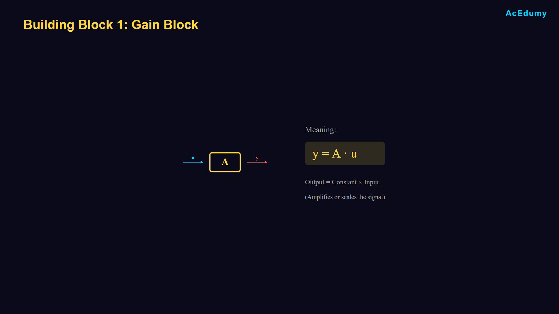
The first building block is the gain block. When you see a box with a constant like A or K inside, it means the output equals the input multiplied by that constant. So, if U enters and Y exits, then Y equals A times U. This simply amplifies or scales the input signal. You can use any constant, A, K, or any other letter.
4. Integrate an input signal
Arrows indicate signal-flow direction, and a minus beside an incoming signal negates that signal before summation. The plus inside a junction denotes summation of these signed inputs. Labels 2.1, 2.2 and 2.3 identify three arrangements, not equal decimal numbers. Integral relations use constant gains and a common initial-condition convention. The grouped construction uses the equation card as its algebraic reference. Use an integrator block.An integral symbol identifies integration with respect to time.Compact integral relation:Retain initial values when turning derivatives into integrals.Narration transcript
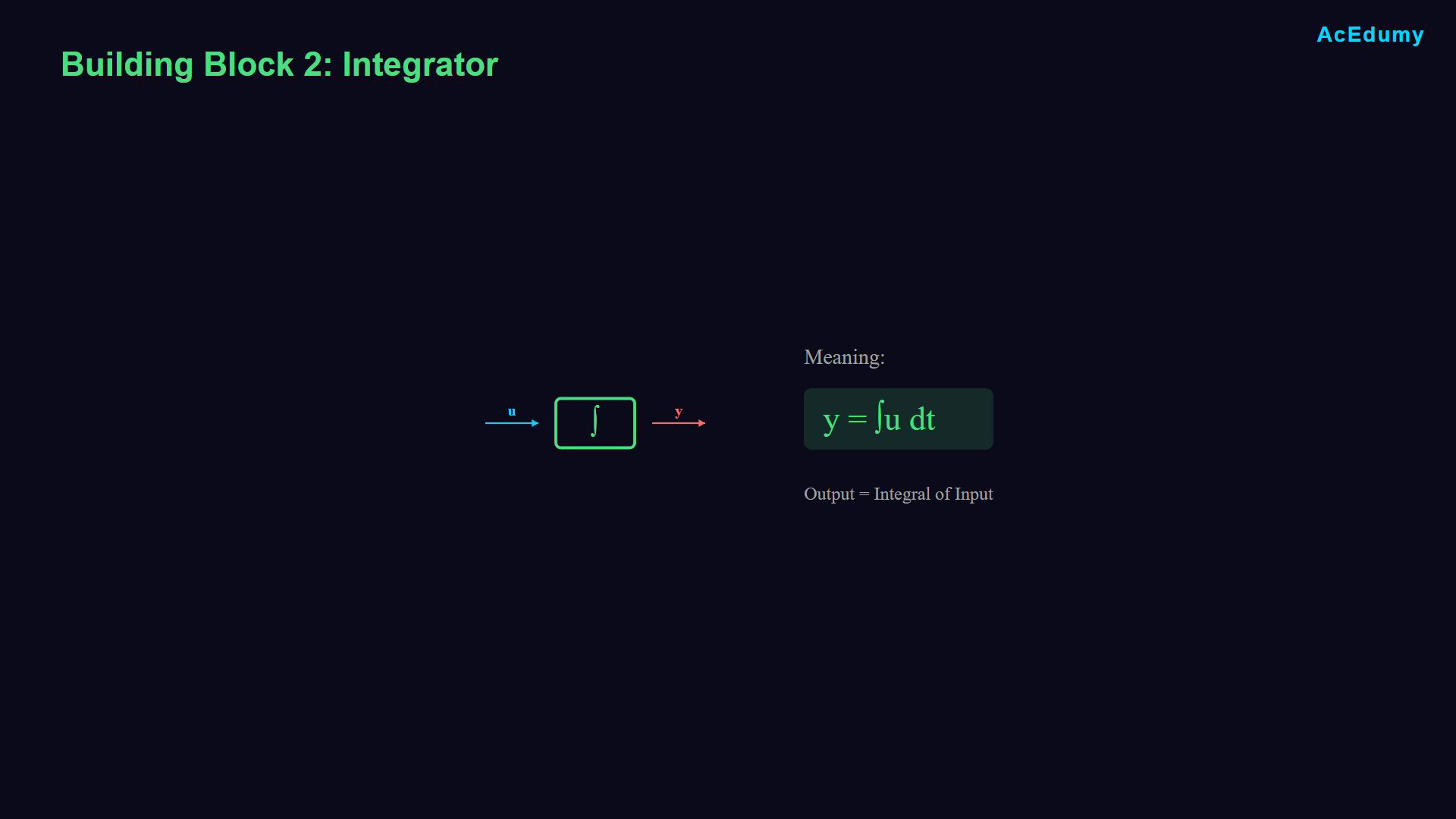
The second building block is the integrator. We show it with an integral symbol inside the box. When input U passes through an integrator, the output Y equals the integral of U with respect to time. This is fundamental for converting differential equations to block diagrams.
5. Combine gain and integration
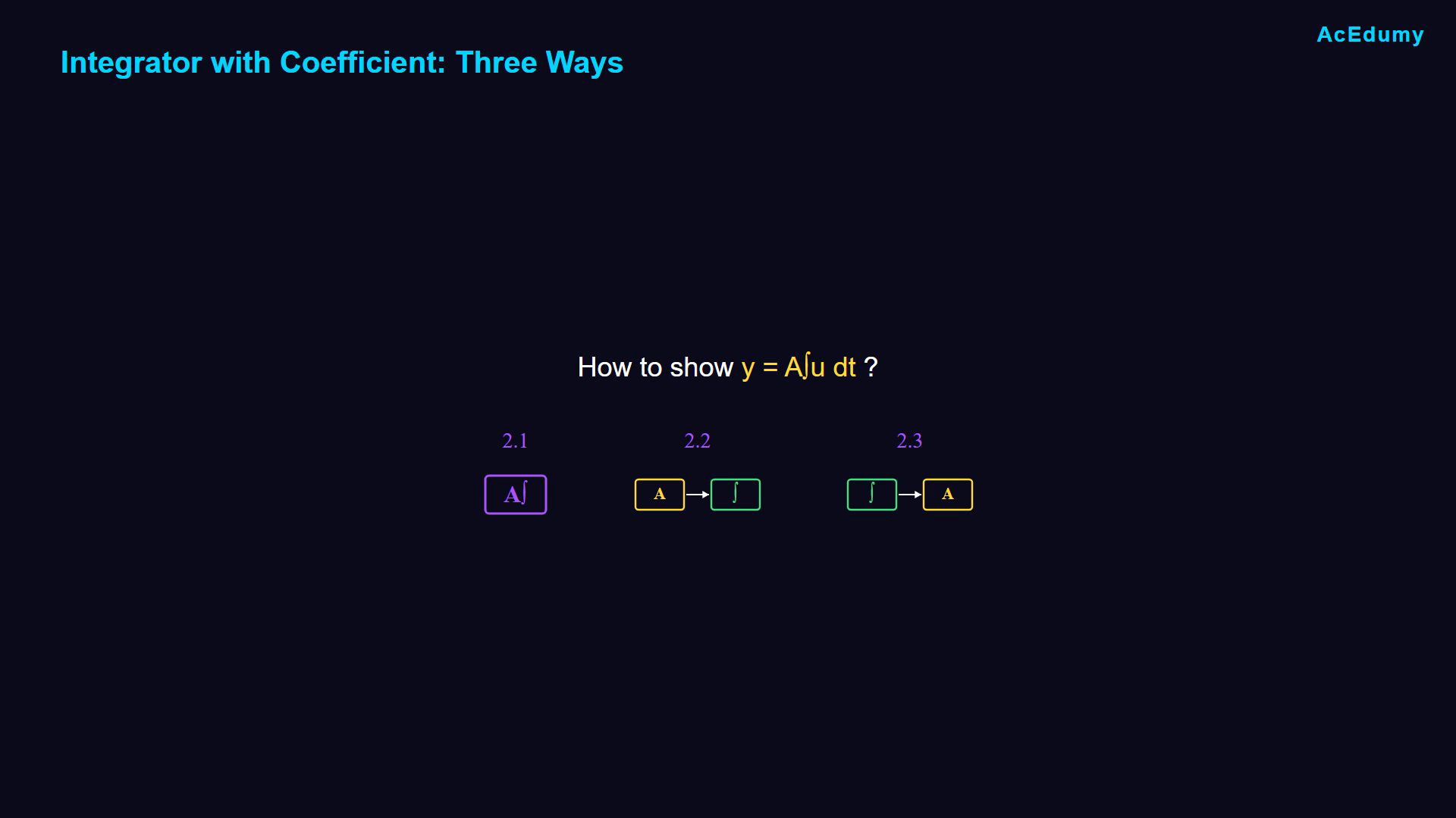
Arrows indicate signal-flow direction, and a minus beside an incoming signal negates that signal before summation. The plus inside a junction denotes summation of these signed inputs. Labels 2.1, 2.2 and 2.3 identify three arrangements, not equal decimal numbers. Integral relations use constant gains and a common initial-condition convention. The grouped construction uses the equation card as its algebraic reference. Combine a constant gain and an integrator:Compare three arrangements under the same initial-condition convention.The labels 2.1, 2.2 and 2.3 identify arrangements.Narration transcript
Now, what if we need to multiply by a coefficient and integrate? We can show this in three equivalent ways. Let's call them 2.1, 2.2 and 2.3.
6. Compare three equivalent orders
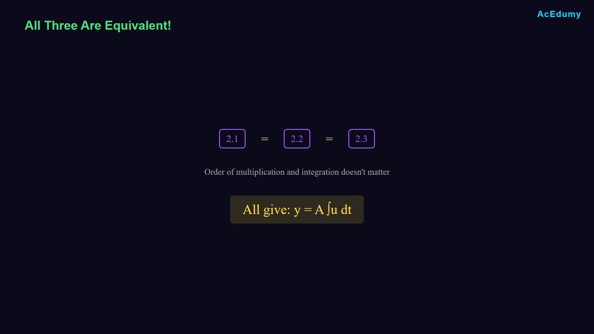
Arrows indicate signal-flow direction, and a minus beside an incoming signal negates that signal before summation. The plus inside a junction denotes summation of these signed inputs. Labels 2.1, 2.2 and 2.3 identify three arrangements, not equal decimal numbers. Integral relations use constant gains and a common initial-condition convention. The grouped construction uses the equation card as its algebraic reference. Arrangement 2.1 combines both operations:Arrangement 2.2 applies gain first:Arrangement 2.3 integrates first:Compare their input-output relationships.For constant gain and matched initial states, the outputs agree.The three arrangements are equivalent; the labels are not equal decimal numbers.Narration transcript
2.1 A single block containing both A and the integral symbol. 2.2 First multiply by A, then integrate. 2.3 First integrate, then multiply by A. Here's the key insight. All three give exactly the same result. The order of multiplication and integration doesn't matter for these linear operations, so 2.1 equals 2.2 equals 2.3.
7. Use a summing junction
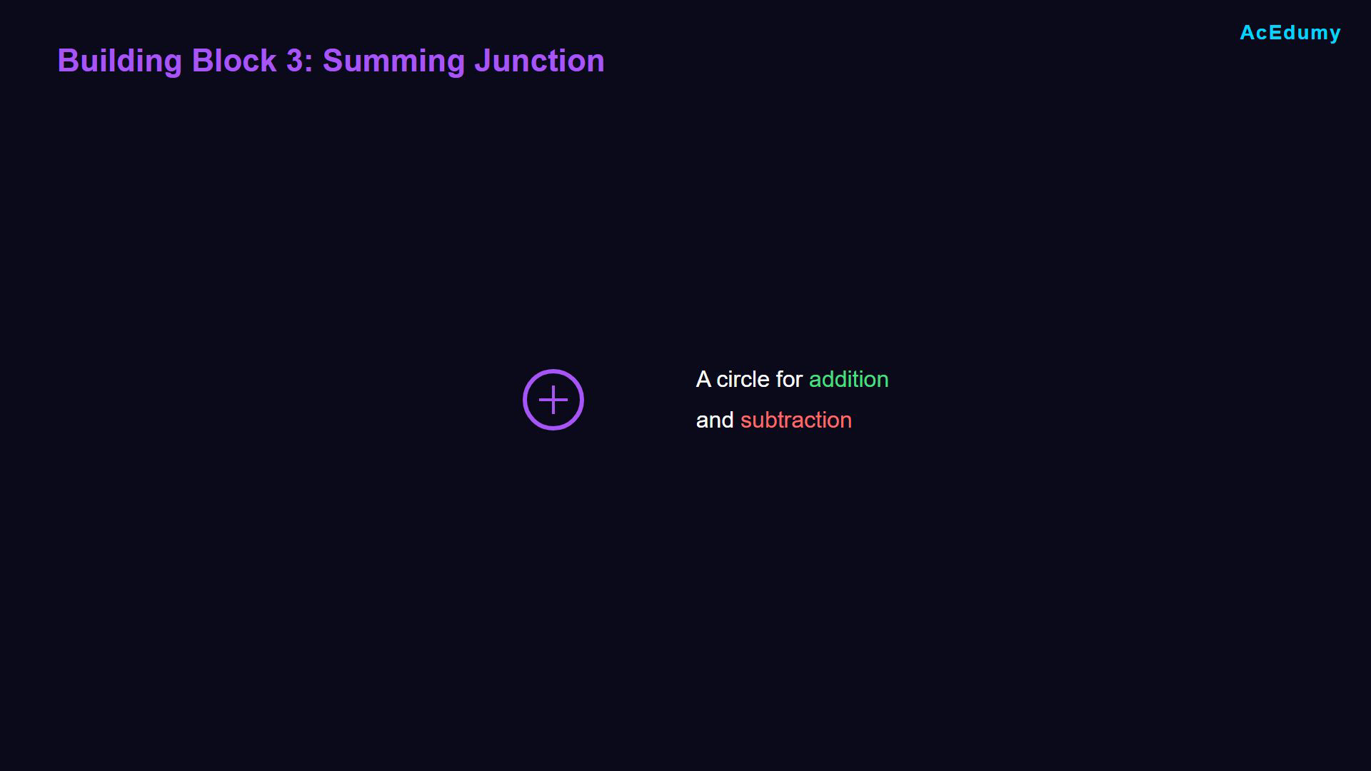
Arrows indicate signal-flow direction, and a minus beside an incoming signal negates that signal before summation. The plus inside a junction denotes summation of these signed inputs. Labels 2.1, 2.2 and 2.3 identify three arrangements, not equal decimal numbers. Integral relations use constant gains and a common initial-condition convention. The grouped construction uses the equation card as its algebraic reference. A summing junction combines signed inputs.Use input signs to represent addition and subtraction.Narration transcript
The third building block is the summing junction, shown as a circle. This is how we represent addition and subtraction in block diagrams.
8. Add two signals
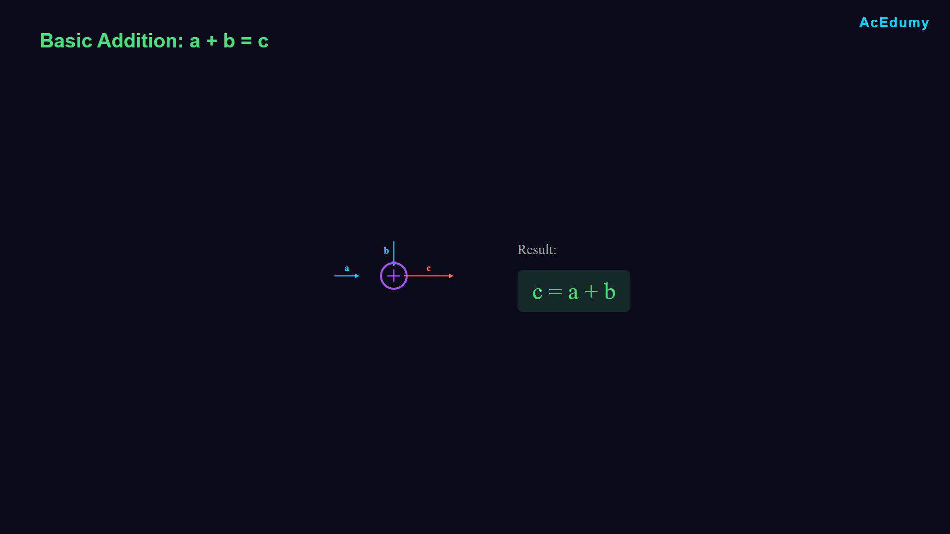
Arrows indicate signal-flow direction, and a minus beside an incoming signal negates that signal before summation. The plus inside a junction denotes summation of these signed inputs. Labels 2.1, 2.2 and 2.3 identify three arrangements, not equal decimal numbers. Integral relations use constant gains and a common initial-condition convention. The grouped construction uses the equation card as its algebraic reference. Begin with two positive inputs.Basic sum:Incoming arrows identify the terms being added.The outgoing arrow carries the result.Narration transcript
Let's start with basic addition. If signal A and signal B both enter the circle and C exits, then C equals A plus B. The arrows pointing into the circle indicate what gets added together. The arrow leaving the circle shows the result.
9. Add multiple signals
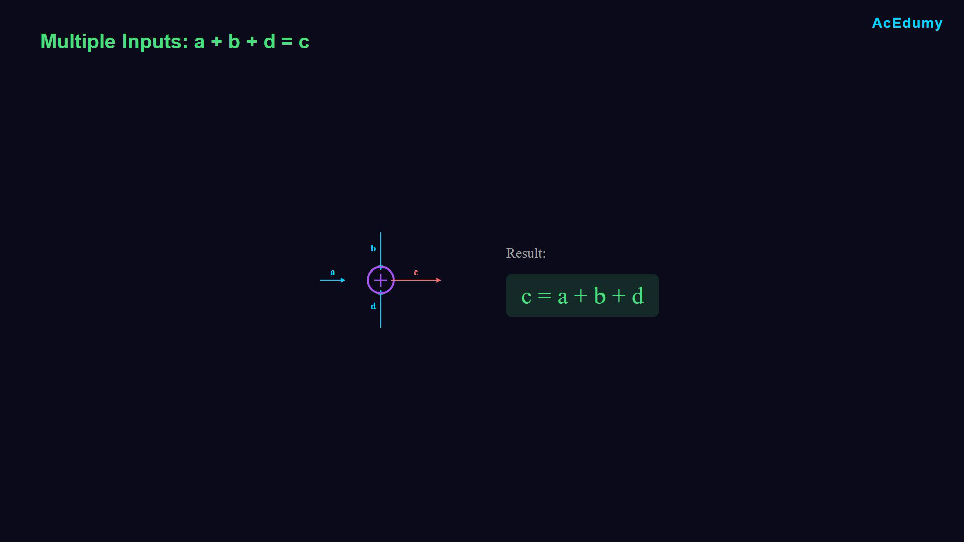
Arrows indicate signal-flow direction, and a minus beside an incoming signal negates that signal before summation. The plus inside a junction denotes summation of these signed inputs. Labels 2.1, 2.2 and 2.3 identify three arrangements, not equal decimal numbers. Integral relations use constant gains and a common initial-condition convention. The grouped construction uses the equation card as its algebraic reference. A summing junction can accept more than two inputs.Three positive inputs:Sum all incoming signals with their indicated signs.Narration transcript
You can have more than two inputs. For example, if A, B, and D all enter the circle and C exits, then C equals A plus B plus D. All incoming signals get summed together.
10. Subtract an input signal
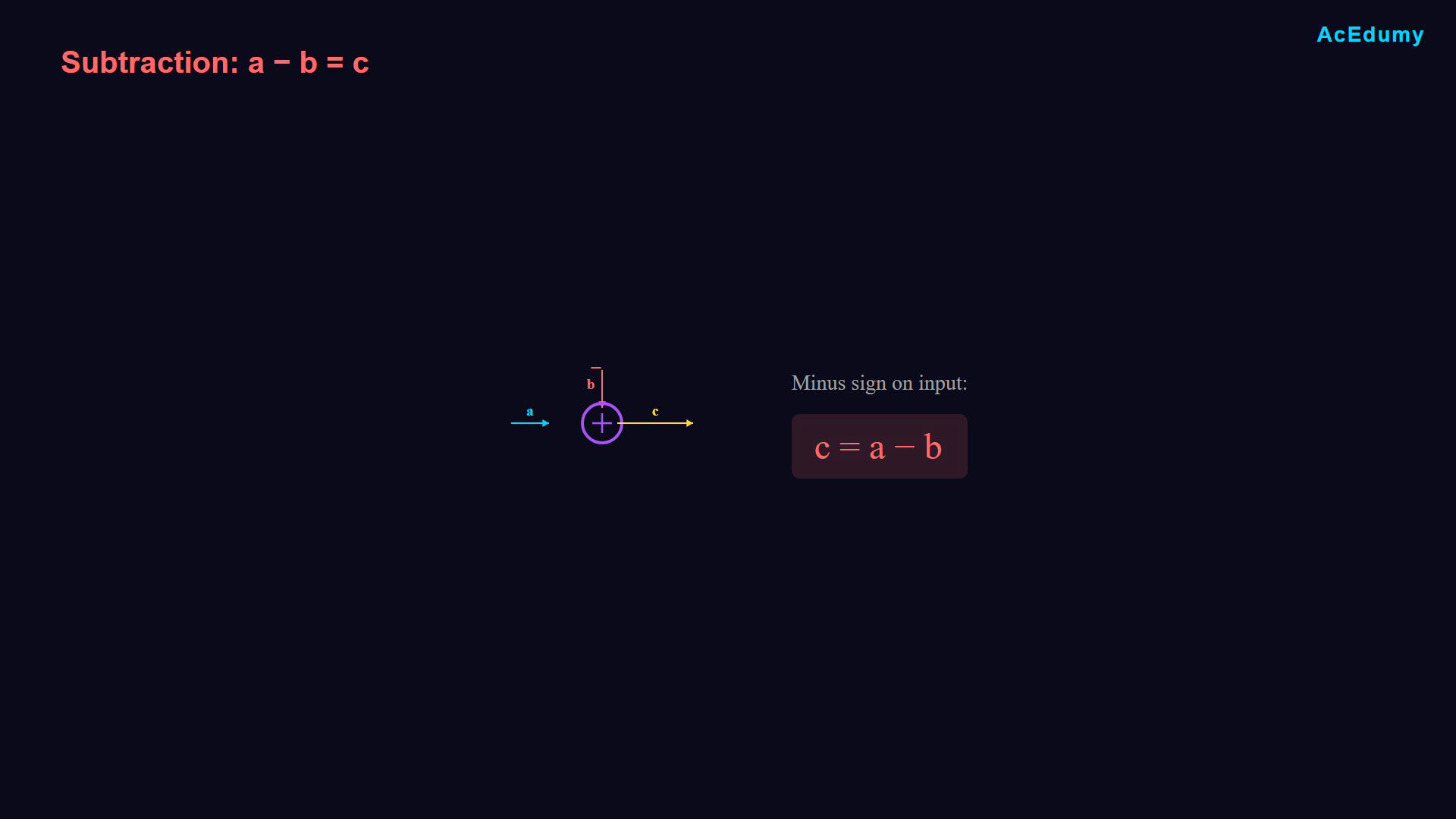
Arrows indicate signal-flow direction, and a minus beside an incoming signal negates that signal before summation. The plus inside a junction denotes summation of these signed inputs. Labels 2.1, 2.2 and 2.3 identify three arrangements, not equal decimal numbers. Integral relations use constant gains and a common initial-condition convention. The grouped construction uses the equation card as its algebraic reference. Place a minus beside the input to be subtracted.One positive and one negative input:Subtracting is adding the negative:Narration transcript
For subtraction, we put a minus sign next to the incoming arrow. If A enters normally and B enters with a minus sign, the output C equals A minus B. Think of it as C equals A plus negative B.
11. State the four-input example
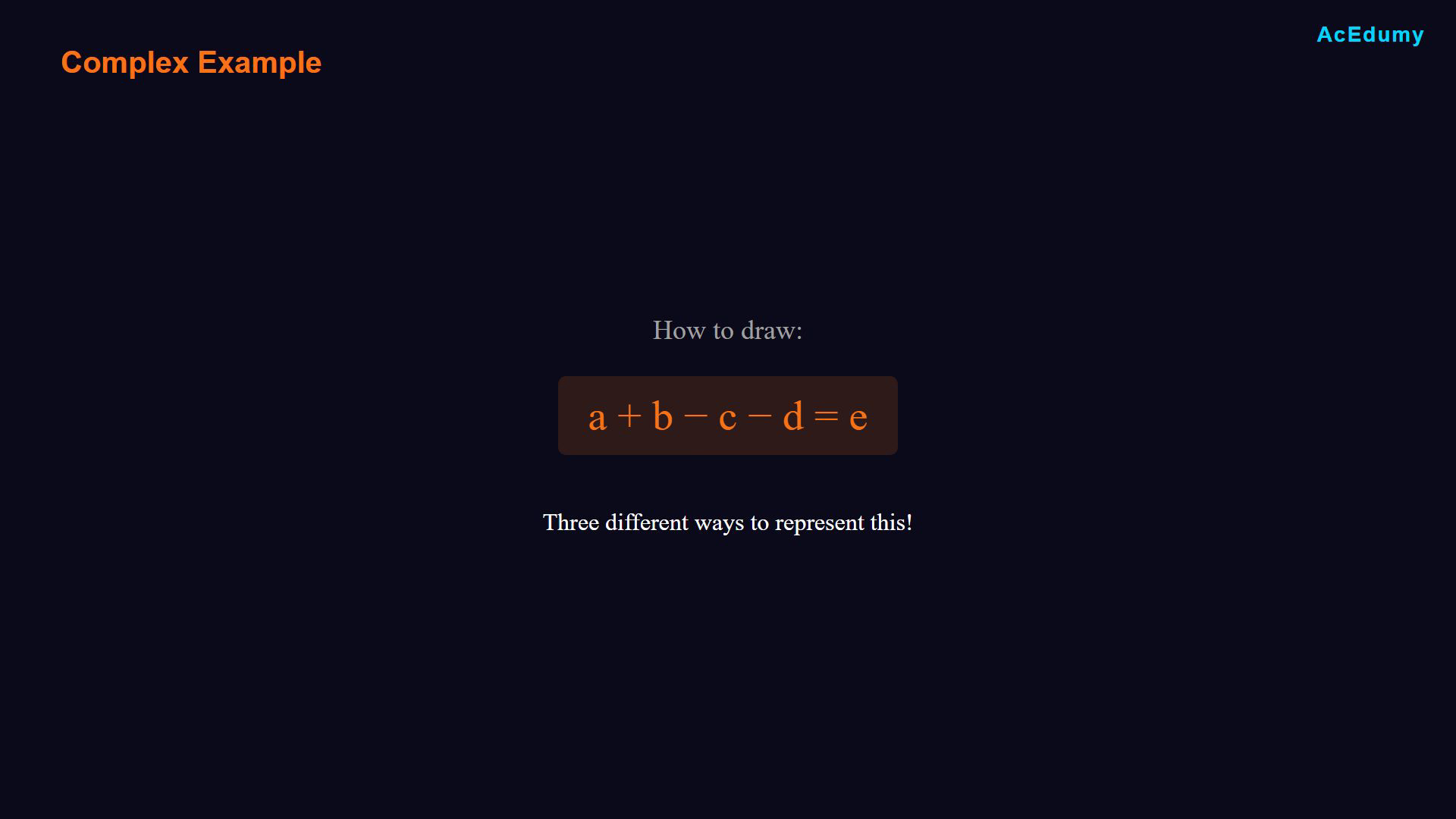
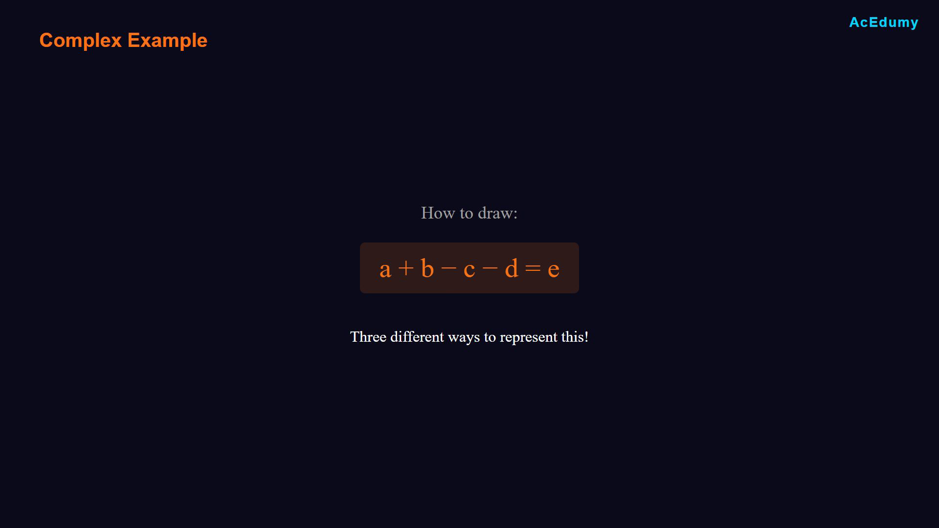
Arrows indicate signal-flow direction, and a minus beside an incoming signal negates that signal before summation. The plus inside a junction denotes summation of these signed inputs. Labels 2.1, 2.2 and 2.3 identify three arrangements, not equal decimal numbers. Integral relations use constant gains and a common initial-condition convention. The grouped construction uses the equation card as its algebraic reference. Consider four independent input signals.The target relation is:Several constructions express this relation.Compare three ways to organize the same signed sum.Narration transcript
Now, let's look at a more complex example. How do we draw A plus B minus C minus D equals E? There are multiple ways to do this. Let me show you three different approaches.
12. Use one signed junction
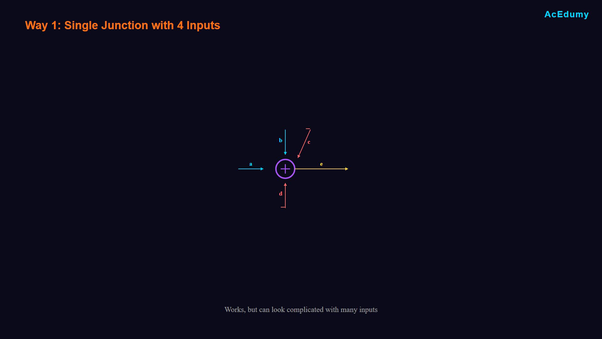
Arrows indicate signal-flow direction, and a minus beside an incoming signal negates that signal before summation. The plus inside a junction denotes summation of these signed inputs. Labels 2.1, 2.2 and 2.3 identify three arrangements, not equal decimal numbers. Integral relations use constant gains and a common initial-condition convention. The grouped construction uses the equation card as its algebraic reference. Use one summing junction with four inputs.Assign a a positive input sign.Assign b a positive input sign.Assign c a negative input sign.Assign d a negative input sign.The outgoing signal is:Make all four input signs clear.Narration transcript
First way, use a single summing junction with four inputs. Signal A enters normally. Signal B enters normally. Signal C enters with a minus sign. Signal D enters with a minus sign. The output is E. This works, but it can look complicated with many inputs.
13. Chain three junctions
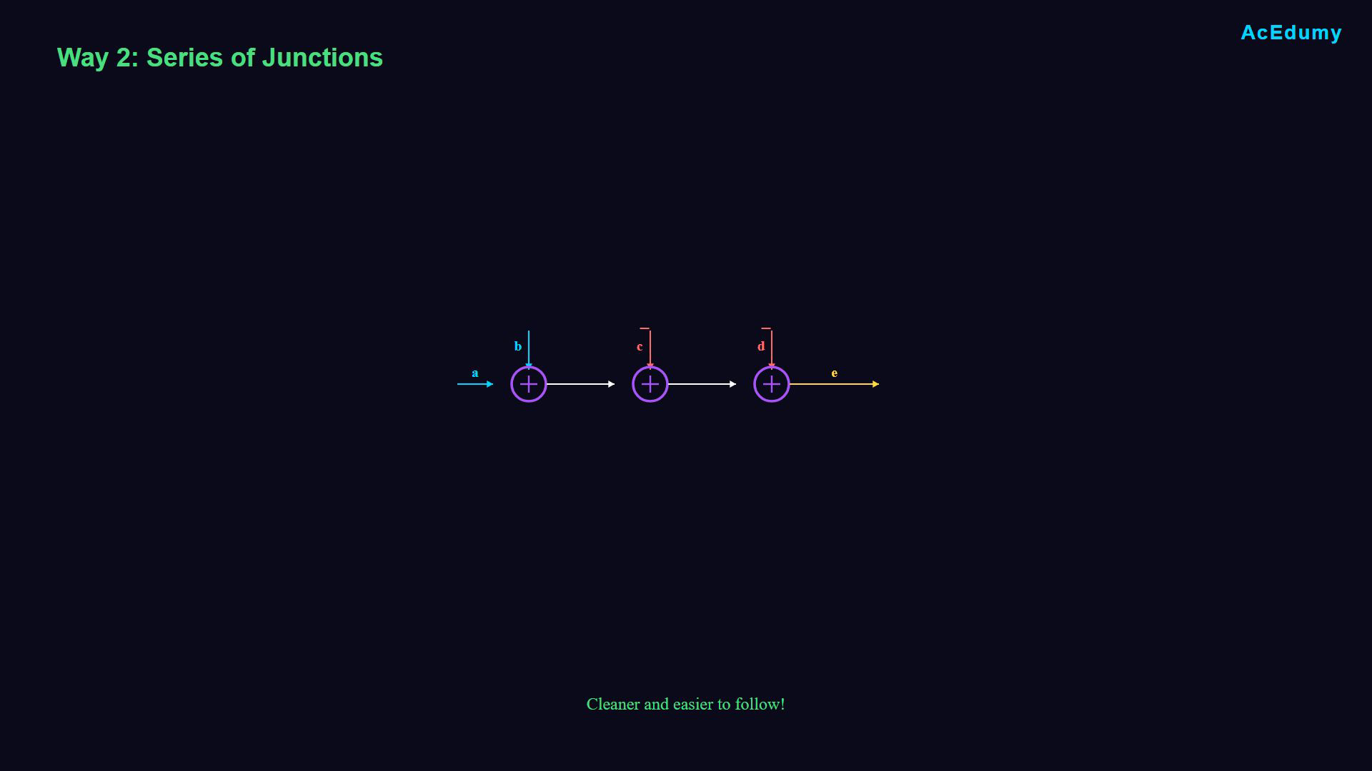
Arrows indicate signal-flow direction, and a minus beside an incoming signal negates that signal before summation. The plus inside a junction denotes summation of these signed inputs. Labels 2.1, 2.2 and 2.3 identify three arrangements, not equal decimal numbers. Integral relations use constant gains and a common initial-condition convention. The grouped construction uses the equation card as its algebraic reference. Use a cascade of summing junctions.First partial result:Subtract c:Subtract d for the final output:Follow each intermediate signal through the cascade.Narration transcript
Second way: Use multiple summing junctions in series. First, add A and B to get a partial result. Then subtract C from that result. Then subtract D to get the final output E. This approach is cleaner and easier to follow.
14. Group the positive and negative sums
Arrows indicate signal-flow direction, and a minus beside an incoming signal negates that signal before summation. The plus inside a junction denotes summation of these signed inputs. Labels 2.1, 2.2 and 2.3 identify three arrangements, not equal decimal numbers. Integral relations use constant gains and a common initial-condition convention. The grouped construction uses the equation card as its algebraic reference. Group the positive and negative contributions.First group:Second group:Subtract the complete second group:The grouped relation is:Narration transcript
Third way, group the operations. First, add A and B in one junction. Separately, add C and D in another junction. Then, subtract the second sum from the first sum to get E. All three ways give the same result, so choose whichever is clearest for your diagram.
15. Review the building blocks
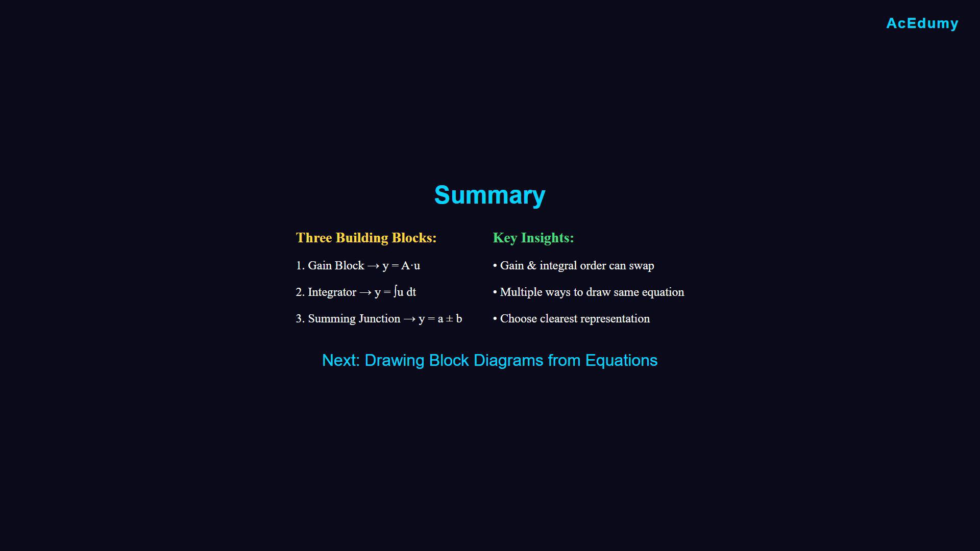
Arrows indicate signal-flow direction, and a minus beside an incoming signal negates that signal before summation. The plus inside a junction denotes summation of these signed inputs. Labels 2.1, 2.2 and 2.3 identify three arrangements, not equal decimal numbers. Integral relations use constant gains and a common initial-condition convention. The grouped construction uses the equation card as its algebraic reference. Review the drawing method.Recall the three main building blocks.Use gain, integration and signed summation.A constant gain can move across an integrator with matched initial conditions.Both orders then give the same output.Use one junction or a cascade while preserving every input sign.Build diagrams from the linear operations introduced here.Next: realize differential equations with these blocks.Continue to the next lesson.Narration transcript
Let's summarize what we learned. We have three main building blocks. The gain block for multiplication, the integrator for integration, and the summing junction for addition and subtraction. For integrators with coefficients, the order doesn't matter. Multiply then integrate or integrate then multiply both work. For summing junctions, you can combine multiple operations into one circle or chain multiple circles together. With these tools, you can construct any block diagram. In the next lesson, we'll apply these concepts to draw actual system diagrams from differential equations. See you then.
Source video: Control Theory #06 - How to Draw Block Diagrams for Control Systems (4:45)