Control Theory · Reducing Two Nested Negative Feedback Loops
#28 Close the inner loop, then the outer unity loop, and verify the signed node equations
Reduce the stated nested-loop topology while preserving the feedback signs and the complete denominator.
Question
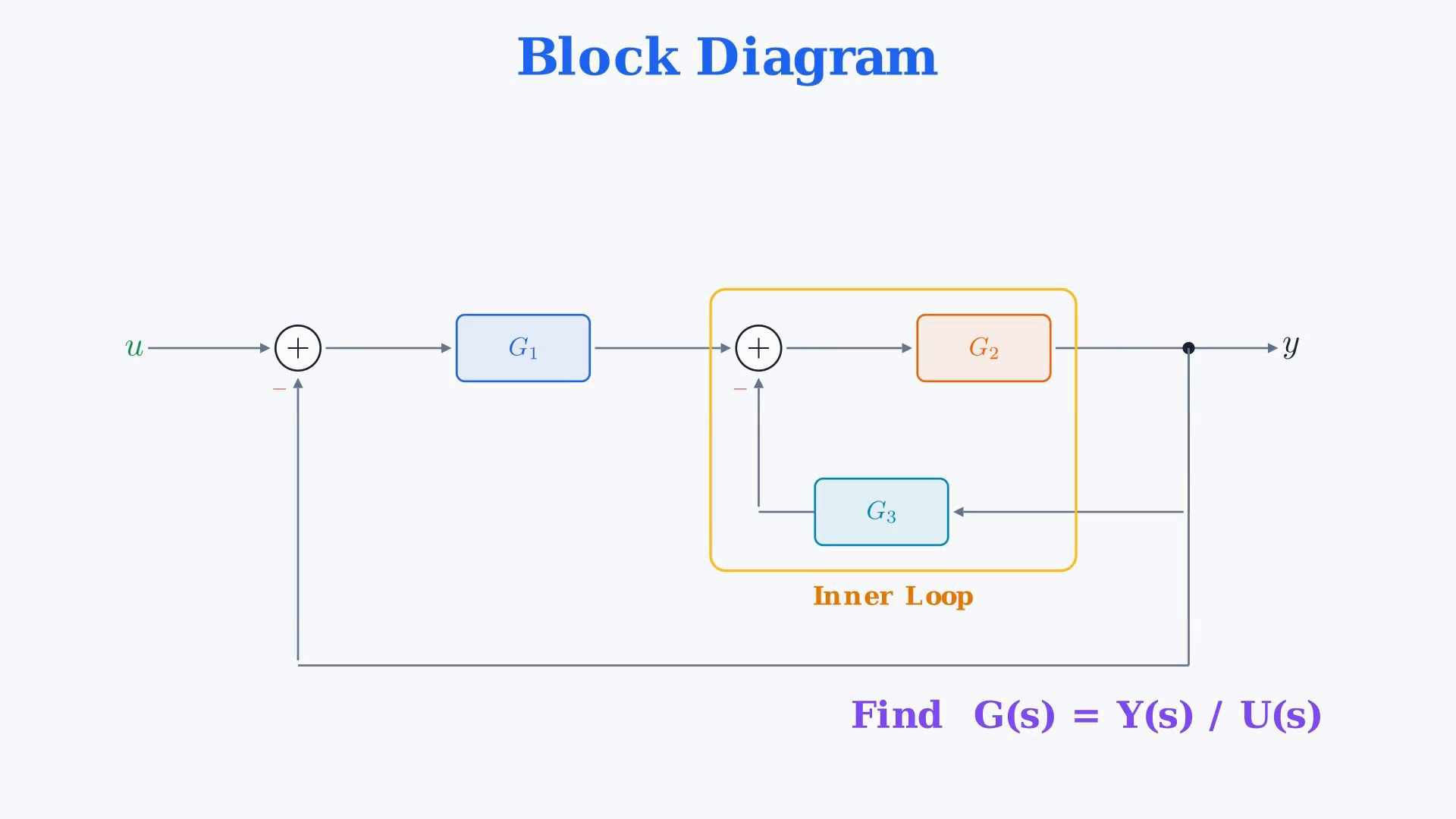
Work with causal continuous-time scalar SISO LTI blocks in the zero state. Let U and Y denote the input and output Laplace transforms. Each block Gi means Gi(s). Assume compatible signal units, defined block maps and a well-posed complete interconnection. Transfer algebra describes the external zero-state map; arbitrary initial states and internal stability require separate analysis. No numerical block values or stability conclusion are given by this symbolic example. Read the actual signed diagram first. The first summing junction subtracts Y directly from U, so E1=U-Y. The output of G1 is V=G1 E1. The second junction subtracts G3 Y from V, so E2=V-G3 Y. The output is Y=G2 E2. Thus both returning feedback branches enter their respective junctions with a minus sign. The narration's short phrase 'Both with a negative sign' should be read against these two explicitly signed returns and the preceding full diagram description. It does not assign an extra minus to either forward block G2 or feedback block G3. Do not turn the forward block into -G2 or count a feedback minus twice. Negative feedback names the interconnection sign; it does not guarantee that a complex-valued transfer function has a positive real value or that the system is stable. First regard V as the independent input to the inner subsystem. Its equation is Y=G2(V-G3Y), giving (1+G2G3)Y=G2V. Where that reduction is defined, define H=G2/(1+G2G3). Then Y=HV. The remaining outer forward path is F=G1H=G1G2/(1+G2G3). Because V=G1(U-Y), the outer unity feedback gives Y=F(U-Y), so the overall transfer is G=F/(1+F). Keep the entire numerator and denominator of each nested fraction grouped. Multiply the top and bottom of [G1G2/(1+G2G3)]/[1+G1G2/(1+G2G3)] by the same factor 1+G2G3. The result is G(s)=G1G2/(1+G2G3+G1G2), equivalently G1G2/[1+G2(G1+G3)]. This staged manipulation requires the intermediate inner-loop inverse to be defined. Do not divide by zero for a singular special choice of constant blocks. The complete node equations remain the appropriate starting point for such a case; a singular isolated inner loop does not automatically imply that the full interconnection is singular. For example, constant G1=1,G2=1,G3=-1 yields the globally defined equation Y=U although the isolated inner denominator is zero. This is a mathematical check of the limitation, not a new block value supplied by the lesson. Verify independently without reducing either loop: Y=G2[G1(U-Y)-G3Y]. Expanding gives Y=G1G2U-G1G2Y-G2G3Y, hence (1+G1G2+G2G3)Y=G1G2U. This also fixes both signs unambiguously. The forward path product is G1G2. If loop products are recorded without their junction signs, they are G2G3 and G1G2; the signed signal-flow loop gains are their negatives. These two loops share the G2 path and the output node. For this topology there is no pair of non-touching loops and therefore no extra product-of-loop-gains term. The narration's 'one plus all loop gains' is specific to this two-loop diagram. It is not a general denominator rule for arbitrary multi-loop networks. Two separate feedback subsystems in series instead have the product of their individual denominators, which includes a cross term. All scalar products here commute; do not transfer the formula unchanged to matrix-valued MIMO blocks. A finite nonzero algebraic denominator at one frequency is not a proof of closed-loop stability. Poles, hidden cancellations and the internal realization must be considered separately. The purpose of this example is to preserve the stated external map through valid block reduction, with the signed-node equation as the final check.
Written solution and narration transcript(shows the full solution)
Below are all the lines written in the notebook together with the full narration transcript.
1. Read both negative feedback loops
Follow the minus sign on each returning feedback branch. The forward blocks remain G1 and G2. The summary card supplies the final formula; products of loop gains cannot be added indiscriminately for other topologies. Read the given signed diagram.The three scalar blocks are G₁, G₂ and G₃.Overall zero-state transfer:Label the signals before reducing the diagram.Outer error:Output of the first block:Inner error:Output relation:Trace both returning feedback paths.The inner return passes through G₃ and is subtracted at the second junction.The outer return is unity and is subtracted at the first junction.These two loops share the G₂ path and output.Find the external map from U to Y in the zero state.Narration transcript
Here is the problem. We are given a block diagram with three transfer functions G1, G2, and G3. We need to find the overall transfer function G of s, which is Y of s divided by U of s. Let me describe the diagram. The input u enters a summing junction with negative feedback. From there, the signal goes through G1. After G1, there is a second summing junction, also with negative feedback. From the second junction, the signal goes through G2, and the output is y. Now the feedback paths. The inner loop takes y, passes it through G3, and feeds it back to the second summing junction with a minus sign. The outer loop takes y directly and feeds it back to the first summing junction, also with a minus sign. So we have two nested loops. Our task: find the equivalent transfer function G of s from u to y.
2. Recall scalar block rules
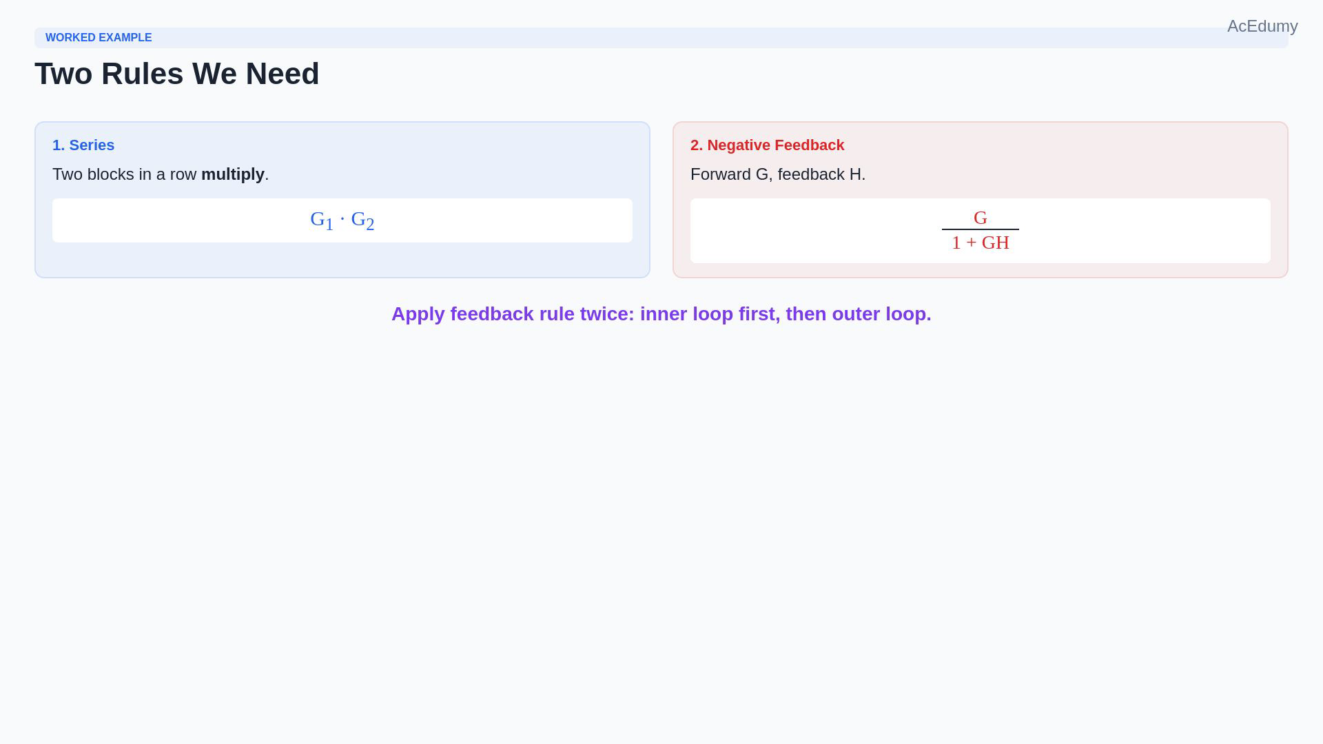
Follow the minus sign on each returning feedback branch. The forward blocks remain G1 and G2. The summary card supplies the final formula; products of loop gains cannot be added indiscriminately for other topologies. Recall the two scalar interconnection rules.First use the series rule.Successive scalar transfer blocks multiply.Series product:Then use the negative feedback rule.Forward G with subtractive return H:Unity feedback:Reduce the inner loop first, then the outer loop, where each inverse is defined.Check the result directly from the original node equations.Narration transcript
Before we start, let us recall two block diagram rules. Rule one: series connection. Two blocks in a row multiply. G1 followed by G2 gives G1 times G2. Rule two: negative feedback. A forward path G with feedback H gives G over one plus G times H. For unity feedback, H equals one, so it becomes G over one plus G. We will apply the feedback rule twice, once for the inner loop and once for the outer loop. That is all we need.
3. Reduce the inner feedback loop
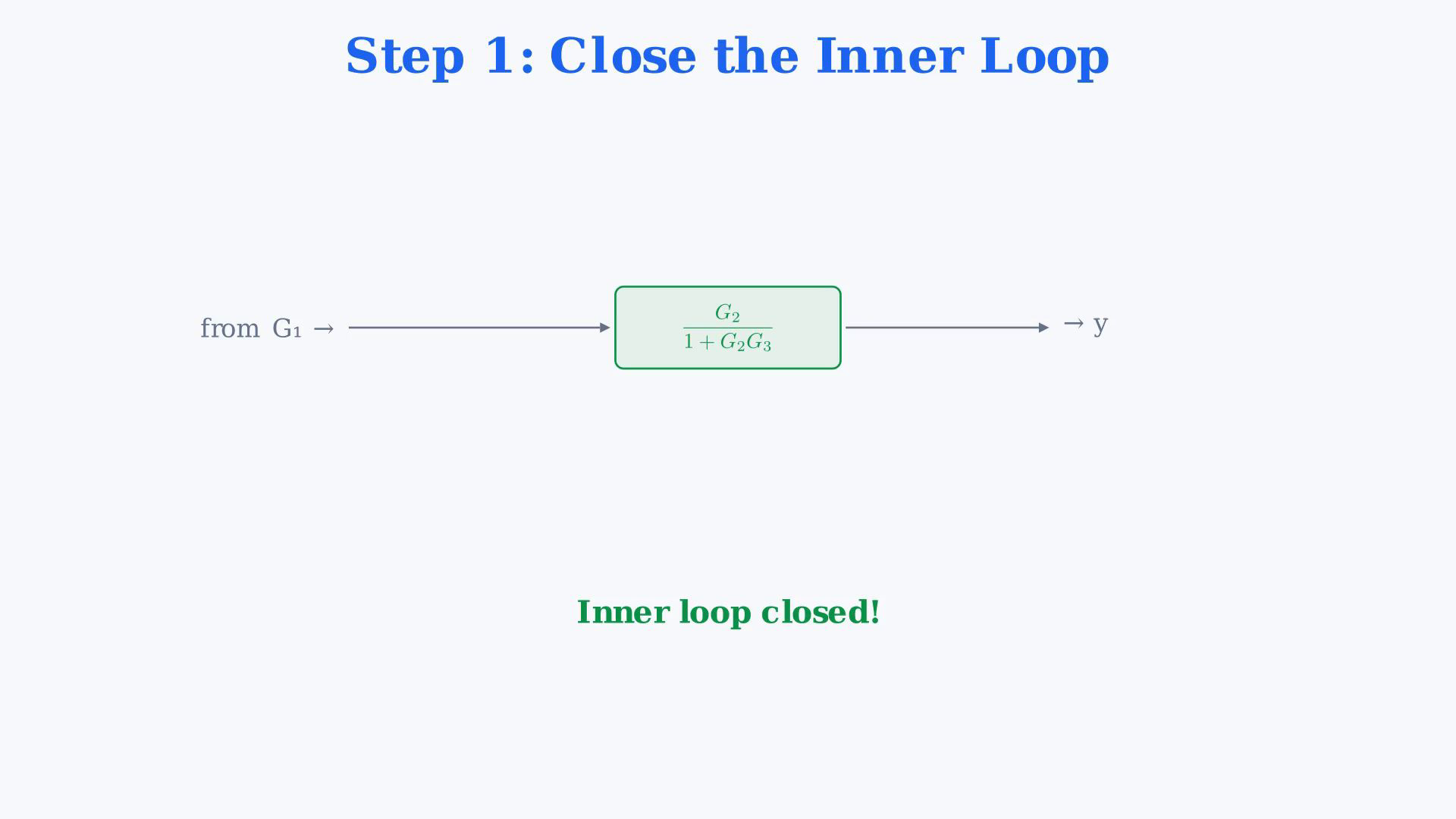
Follow the minus sign on each returning feedback branch. The forward blocks remain G1 and G2. The summary card supplies the final formula; products of loop gains cannot be added indiscriminately for other topologies. Close the inner feedback loop.Regard V as the input to this inner subsystem.Its forward block is G₂.Its return block is G₃.Both feedback returns are subtracted at their junctions; do not add a minus to G₂.Inner node equation:Collect the output:Defined inner-loop transfer:The outer unity feedback now surrounds the series connection of G₁ and H.Narration transcript
Step one: close the inner loop. Look at the inner loop. The forward path is G2. The feedback path is G3. Both with a negative sign. Using the feedback rule, the closed loop transfer function is the forward path divided by one plus forward times feedback. That gives us G2 over one plus G2 times G3. After this step, the inner loop is replaced by a single block: G2 over one plus G2 G3. Now the diagram is simpler: u enters a summing junction with negative unity feedback, then goes through G1, then through the inner closed loop block G2 over one plus G2 G3, and the output is y.
4. Close the outer unity loop
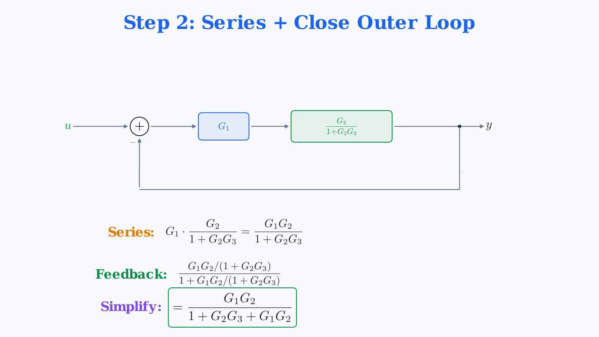
Follow the minus sign on each returning feedback branch. The forward blocks remain G1 and G2. The summary card supplies the final formula; products of loop gains cannot be added indiscriminately for other topologies. Combine the forward blocks and close the outer loop.G₁ is in series with the reduced inner block H.Series forward path:Grouped forward transfer:The outer junction still subtracts Y from U.Overall unity-feedback transfer:Numerator of the nested fraction:Denominator of the nested fraction:Multiply top and bottom by the same defined factor one plus G₂G₃.Simplified numerator:Simplified denominator:Narration transcript
Step two: combine and close the outer loop. First, G1 and the inner closed loop block are in series. Using the series rule, we multiply them: G1 times G2 over one plus G2 G3. That gives G1 G2 over one plus G2 G3. Now we have a single forward path with unity negative feedback from y to the input. Applying the feedback rule one more time, the overall transfer function is the forward path divided by one plus the forward path. The numerator is G1 G2 over one plus G2 G3. The denominator is one plus G1 G2 over one plus G2 G3. To simplify, multiply top and bottom by one plus G2 G3. The numerator becomes G1 G2. The denominator becomes one plus G2 G3 plus G1 G2.
5. Verify the signed node equations
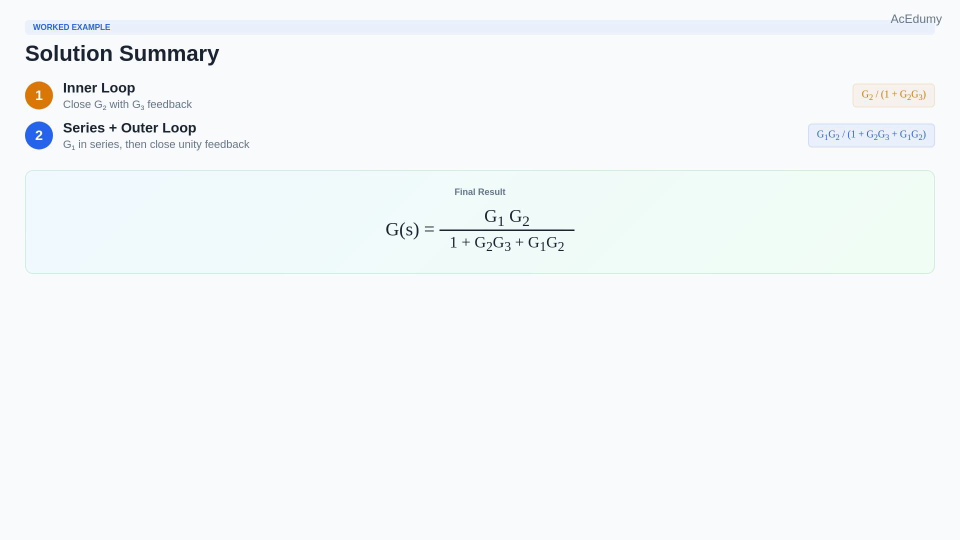
Follow the minus sign on each returning feedback branch. The forward blocks remain G1 and G2. The summary card supplies the final formula; products of loop gains cannot be added indiscriminately for other topologies. Write and verify the final external map.Overall transfer:Equivalent factored form:Verify from the original signed node equations.Direct equation:Unsigned inner-loop product:Unsigned outer-loop product:Each signed signal-flow loop gain includes its negative junction sign.For these touching loops:The direct equation agrees with the reduction; stability is a separate question.Narration transcript
Here is the final answer. G of s equals G1 G2 divided by one plus G2 G3 plus G1 G2. We can also factor the denominator as one plus G2 times the quantity G1 plus G3. Let us verify by tracing the signal. From u, the signal goes through G1, then through G2, giving G1 G2 in the forward path. The inner loop gain is G2 G3. The outer loop gain is G1 G2. Both are negative feedback. The denominator should be one plus all loop gains: one plus G2 G3 plus G1 G2. That matches.
6. Review the nested-loop result
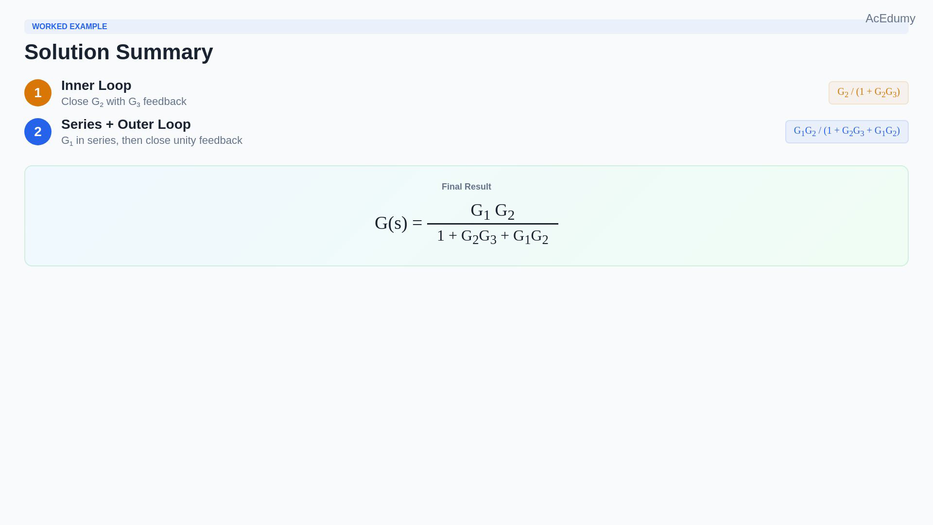
Follow the minus sign on each returning feedback branch. The forward blocks remain G1 and G2. The summary card supplies the final formula; products of loop gains cannot be added indiscriminately for other topologies. Review the reduction.The diagram contains two nested negative feedback loops.Reduce it in two stages when the intermediate inverse exists.Inner transfer:Combine G₁ with H, then apply the outer unity feedback.Overall transfer:Use the original signed nodes to check the final result.Narration transcript
Let us recap. We started with a block diagram containing two nested feedback loops. In two steps, we found the overall transfer function. Step one: we closed the inner loop, G2 with G3 feedback, to get G2 over one plus G2 G3. Step two: we combined G1 in series with the inner closed loop, then closed the outer unity feedback loop. Final result: G of s equals G1 G2 over one plus G2 G3 plus G1 G2. Two rules, two steps, done.
Source video: Control Theory #28 — Nested Loop Block Diagram (Worked Example 5) (4:44)