Control Theory · Parallel RLC Plant Modeling
#05 Current balance, element laws and a second-order voltage model
Derive the voltage model of a current-driven parallel RLC network and preserve its initial-state constraint.
Question
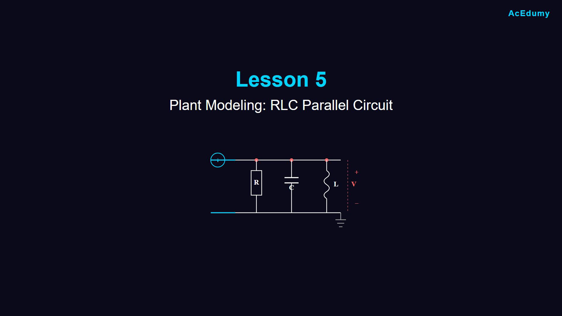
Model an ideal parallel RLC network driven by an externally supplied current. Take R, C and L as finite, positive constants. The resistor, capacitor and inductor share the same top and bottom nodes. Define V as the top-node voltage relative to the grounded bottom node and define the three passive branch currents downward, from the positive-voltage terminal toward ground. The illustration labels input current on the upper lead and leaves the external driving port at the two left leads; the circle is not a complete two-terminal current-source symbol. Supply the input current through that external port. Set u(t)=i(t) and y(t)=V(t). These are time-domain variables; capitalization in the narration does not denote phasors or Laplace transforms. Kirchhoff current law gives i=i1+i2+i3. The branch indices are one for the resistor, two for the capacitor and three for the inductor. Ohm's law gives i1=V/R. For the constant capacitor, Q=CV and i2=dQ/dt=C d V/dt. Charge is on the positive-voltage plate. For the inductor, V=L di3/dt. The generic i in the source's standalone inductor law refers to that branch current, not to the total input current. The diagram has small capacitor lettering near its lead, but its two plates, common-node connections and branch identity remain visible. Integrating the inductor law gives i3(t)=i3(t0)+(1/L) integral from t0 to t of V(xi) dxi. An indefinite integral in the source carries an arbitrary integration constant; do not silently assume zero initial current or replace it by a definite integral with zero constant. Substituting the three branches gives i(t)=V(t)/R+C V'(t)+i3(t0)+(1/L) integral from t0 to t of V(xi) dxi. The voltage derivative and inductor current need not be zero initially. Differentiate the entire current balance to obtain i'=V'/R+C V''+V/L. In particular, the input on the left is differentiated too. Substituting y=V and u=i and collecting output terms gives C y''+(1/R)y'+(1/L)y=u'. The first and second dots in the source mean time derivatives. The order is two because the highest output derivative is the second; the right side remains u', not u. The dimensions of every differentiated term are amperes per second. This is a plant model and does not by itself design a controller or guarantee tracking. Differentiation removes a constant, so the original current balance must also hold at the initial time: i3(t0)=u(t0)-y(t0)/R-C y'(t0). Equivalently, choose the initial capacitor voltage and inductor current and use the input value to determine the compatible initial voltage derivative. The second-order equation alone admits an arbitrary constant mismatch in Kirchhoff current balance if this constraint is omitted. For example y=0 and constant u=1 satisfy the differentiated equation but require inductor current 1, not all-zero branch currents. Do not count that integration constant twice. The classical derivative equation applies on intervals with sufficient signal regularity. Switching inputs require the appropriate one-sided state continuity and jump relations, or a consistent distributional interpretation; do not set an input impulse derivative to zero at a jump. This lesson converts an integral form to an ordinary differential form for convenience. Integral equations and integrator blocks remain valid representations in control theory. The branch integral, differentiated equation and subsequent block-diagram work describe the same physical model when their initial conditions agree.
Written solution and narration transcript(shows the full solution)
Below are all the lines written in the notebook together with the full narration transcript.
1. Introduce the parallel RLC model
Read branch currents from the positive-voltage node toward ground. The circle on the upper lead labels the external input current; the two left leads form the driving port. Integrals include the inductor initial current. The preference for an equation without integrals applies to this derivation. Plant modeling: parallel RLC circuit.Derive a voltage-output model driven by current.Extend the RC modeling method to an inductor branch.Narration transcript
Welcome to Lesson 5 of Control Theory. Today, we'll work through another plant modeling example, the RLC parallel circuit. This builds on what we learned with the RC circuit in our previous lesson.
2. Recall the RC modeling method
Read branch currents from the positive-voltage node toward ground. The circle on the upper lead labels the external input current; the two left leads form the driving port. Integrals include the inductor initial current. The preference for an equation without integrals applies to this derivation. Recall the differential-equation model of an RC circuit.Identify the input, output and element laws.Connect a resistor, capacitor and inductor across the same two nodes.Narration transcript
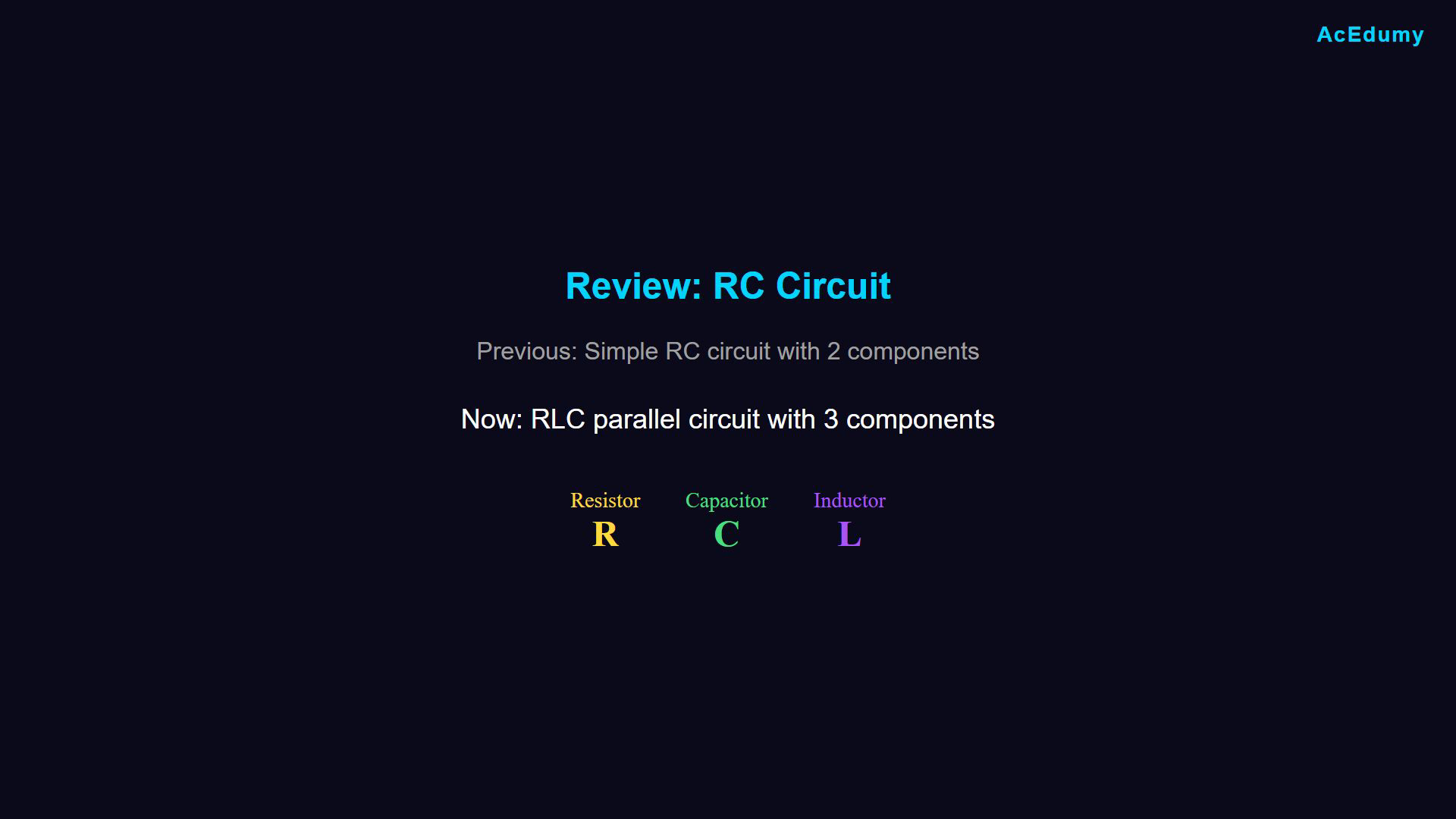
In our last video, we modeled an RC circuit using differential equations. We learned how to identify inputs and outputs, and how to derive the mathematical model. Now we'll apply the same approach to a more complex circuit with three components, a resistor, capacitor, and inductor, all connected in parallel.
3. Read the two-node circuit
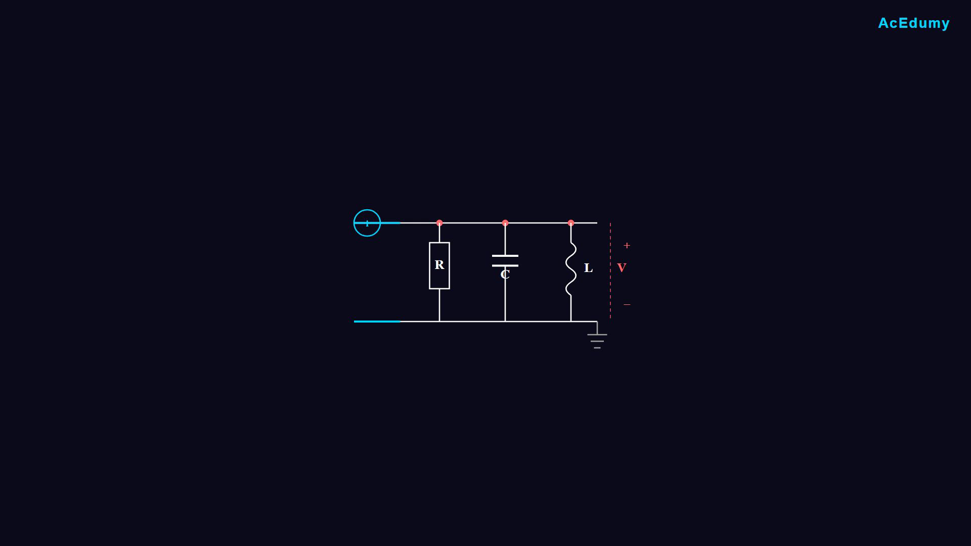
Read branch currents from the positive-voltage node toward ground. The circle on the upper lead labels the external input current; the two left leads form the driving port. Integrals include the inductor initial current. The preference for an equation without integrals applies to this derivation. Read the parallel RLC network.All three elements share the same two nodes and voltage.An external current drive supplies the port; measure voltage across the parallel branches.Narration transcript
Here's our RLC parallel circuit. We have a resistor R, a capacitor C, and an inductor L, all sharing the same two nodes. A current source provides the input current I, and we measure the output voltage V across the parallel combination.
4. Define current input and voltage output
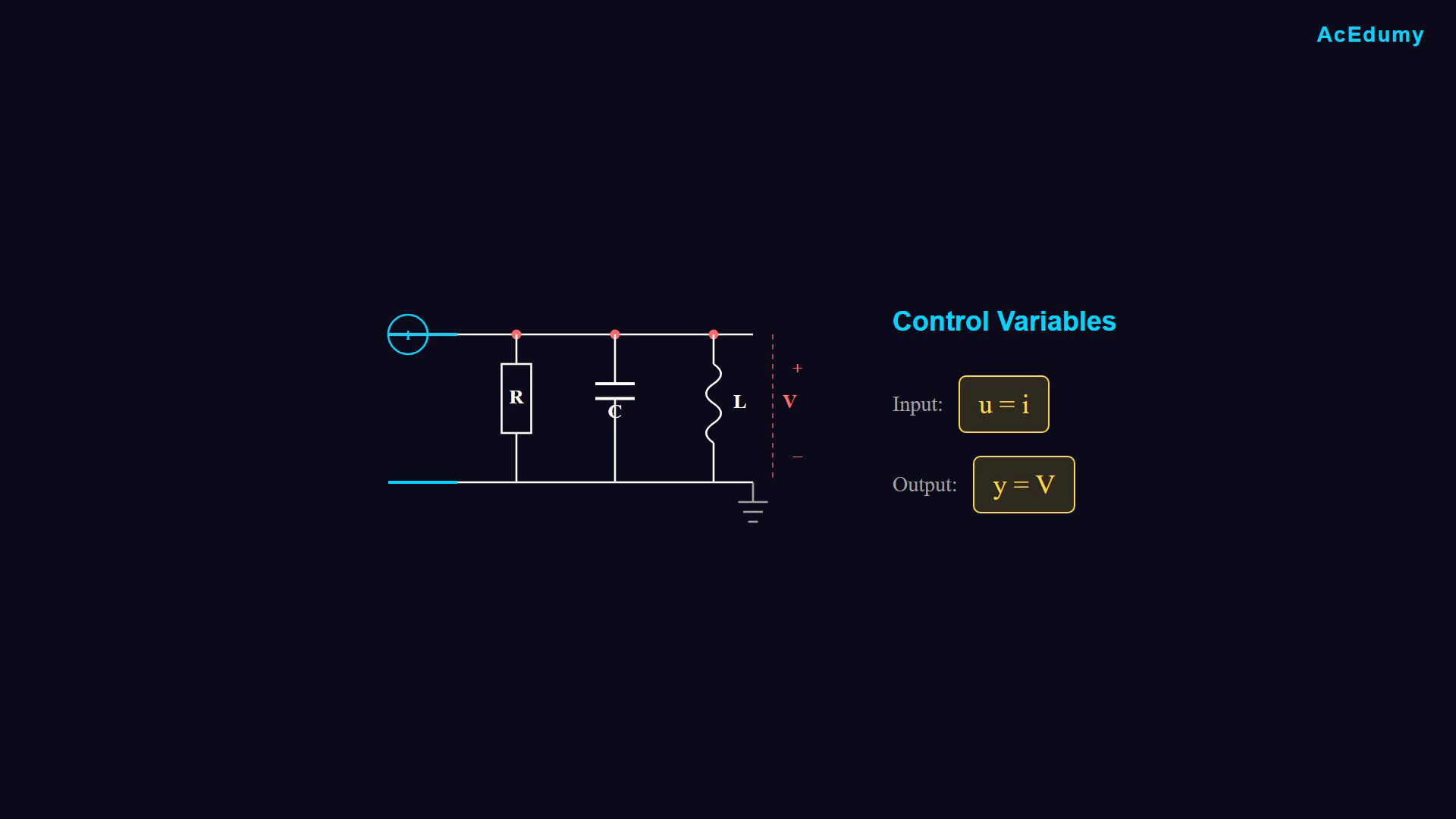
Read branch currents from the positive-voltage node toward ground. The circle on the upper lead labels the external input current; the two left leads form the driving port. Integrals include the inductor initial current. The preference for an equation without integrals applies to this derivation. Define the input and output before writing the model.Choose the quantity to control.Identify the available driving quantity.Control the common voltage using the supplied current.Use u for input and y for output.Control variables:Narration transcript
The first rule of control engineering is to clearly define our input and output. What do we want to achieve? And with what? We want to control the output voltage V using the input current I. In control notation, input is represented by U and output by Y. So we define U equals I and Y equals V.
5. Apply Kirchhoff current balance
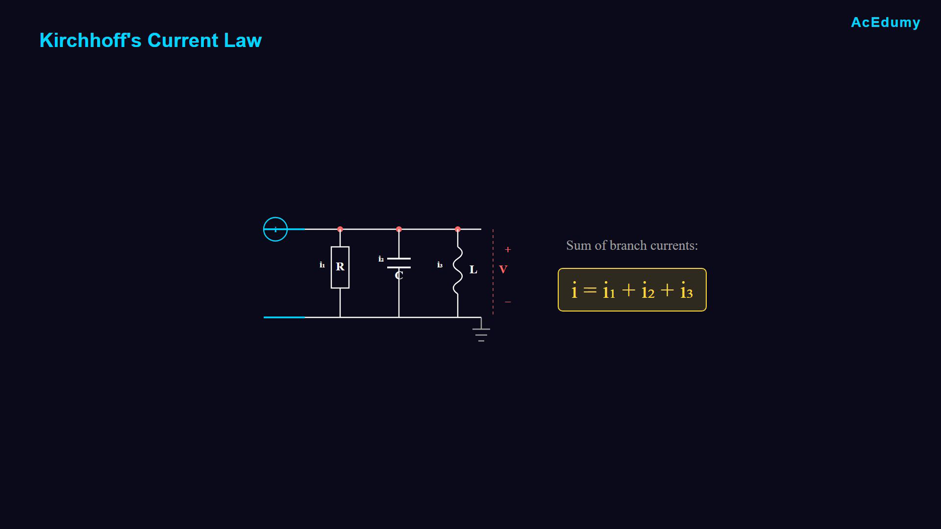
Read branch currents from the positive-voltage node toward ground. The circle on the upper lead labels the external input current; the two left leads form the driving port. Integrals include the inductor initial current. The preference for an equation without integrals applies to this derivation. Apply current conservation at the top node.Input current splits among the three branches.Kirchhoff current law equates total incoming and outgoing current.Branch balance:Narration transcript
Now, let's analyze the circuit. The main current I enters the parallel combination and splits into three branches. By Kirchhoff's current law, the sum of currents entering a node equals the sum leaving. So, our main current I equals I1 plus I2 plus I3, where each represents the current through the resistor, capacitor and inductor respectively.
6. Identify the resistor branch
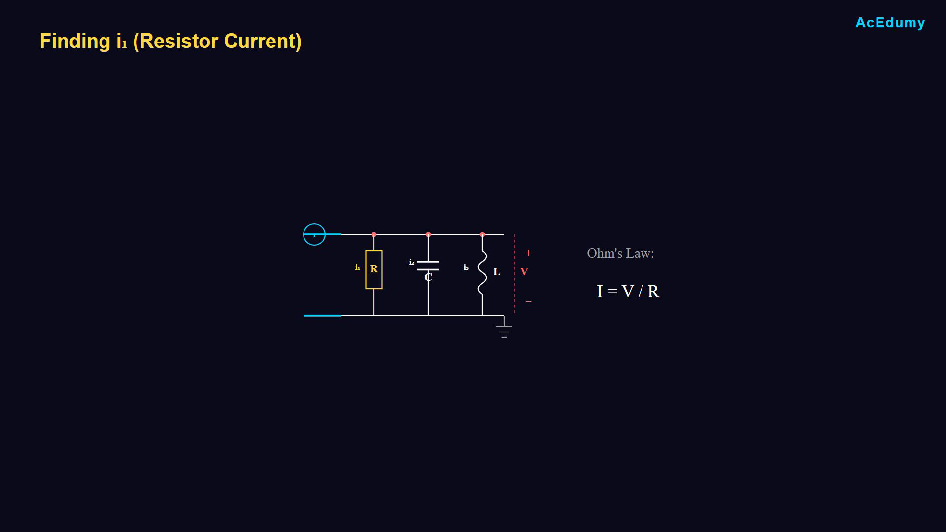
Read branch currents from the positive-voltage node toward ground. The circle on the upper lead labels the external input current; the two left leads form the driving port. Integrals include the inductor initial current. The preference for an equation without integrals applies to this derivation. Start with the resistor branch.The resistor has the same voltage as the other parallel elements.The lower node is the zero-volt reference.Narration transcript
Let's find each branch current, starting with Ione through the resistor. In a parallel circuit, all components share the same voltage. The voltage across the resistor equals V, and the other end connects to ground, which is 0 volts.
7. Calculate resistor current
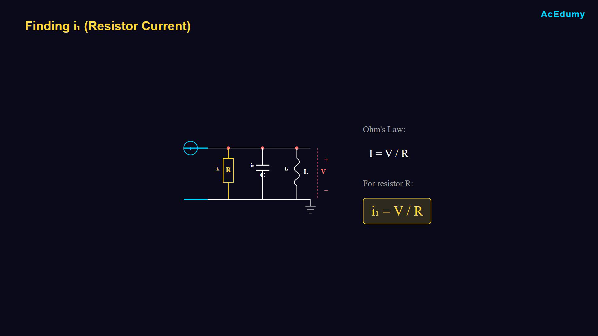
Read branch currents from the positive-voltage node toward ground. The circle on the upper lead labels the external input current; the two left leads form the driving port. Integrals include the inductor initial current. The preference for an equation without integrals applies to this derivation. Ohm’s law relates resistor current to voltage and resistance.The resistor voltage is the top-node voltage relative to ground.Resistor branch:This is the current through R.Narration transcript
Using Ohm's law, current equals voltage divided by resistance. The voltage difference is V minus zero, which is simply V. Therefore, I1 equals V divided by R. This is the resistor current.
8. Recall capacitor charge
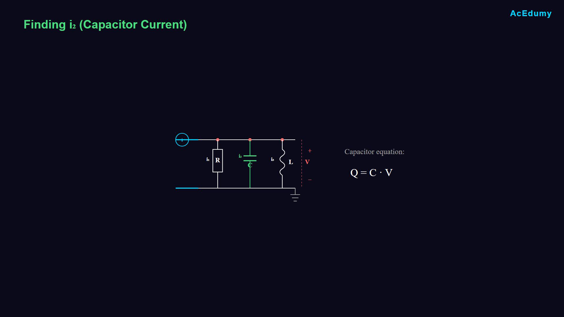
Read branch currents from the positive-voltage node toward ground. The circle on the upper lead labels the external input current; the two left leads form the driving port. Integrals include the inductor initial current. The preference for an equation without integrals applies to this derivation. Identify the capacitor current.Recall charge as a function of voltage.Constant-capacitance relation:Differentiate charge to obtain current.Narration transcript
Next, let's find I2, the capacitor current. For this, we need to recall the fundamental capacitor relationship. Charge Q equals capacitance C times voltage V. But we need current, not charge.
9. Differentiate capacitor charge
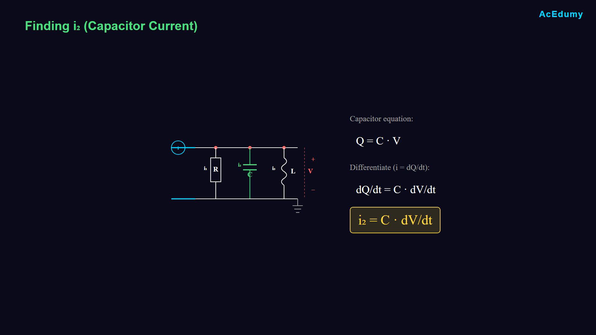
Read branch currents from the positive-voltage node toward ground. The circle on the upper lead labels the external input current; the two left leads form the driving port. Integrals include the inductor initial current. The preference for an equation without integrals applies to this derivation. Differentiate the charge relation with respect to time.Keep the constant capacitance outside the derivative.Capacitor branch:Capacitor current depends on the rate of voltage change.Narration transcript
Current is defined as the rate of change of charge over time, so we differentiate both sides of Q equals Cv with respect to time. The capacitance C is constant, so it comes out of the derivative. This gives us I2 equals C times dv over dt. The capacitor current depends on how fast the voltage is changing.
10. Recall the inductor voltage law
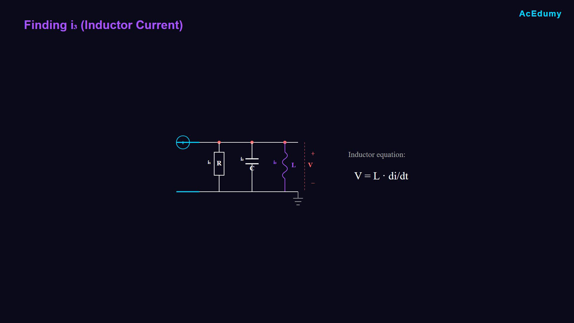
Read branch currents from the positive-voltage node toward ground. The circle on the upper lead labels the external input current; the two left leads form the driving port. Integrals include the inductor initial current. The preference for an equation without integrals applies to this derivation. Identify the inductor current.Inductor branch law:The voltage depends on the rate of inductor-current change.Narration transcript
Finally, let's find I3, the inductor current. For inductors, we use the voltage-current relationship, V equals L times Di over DT. This tells us the voltage across an inductor depends on how fast the current is changing.
11. Integrate the inductor voltage
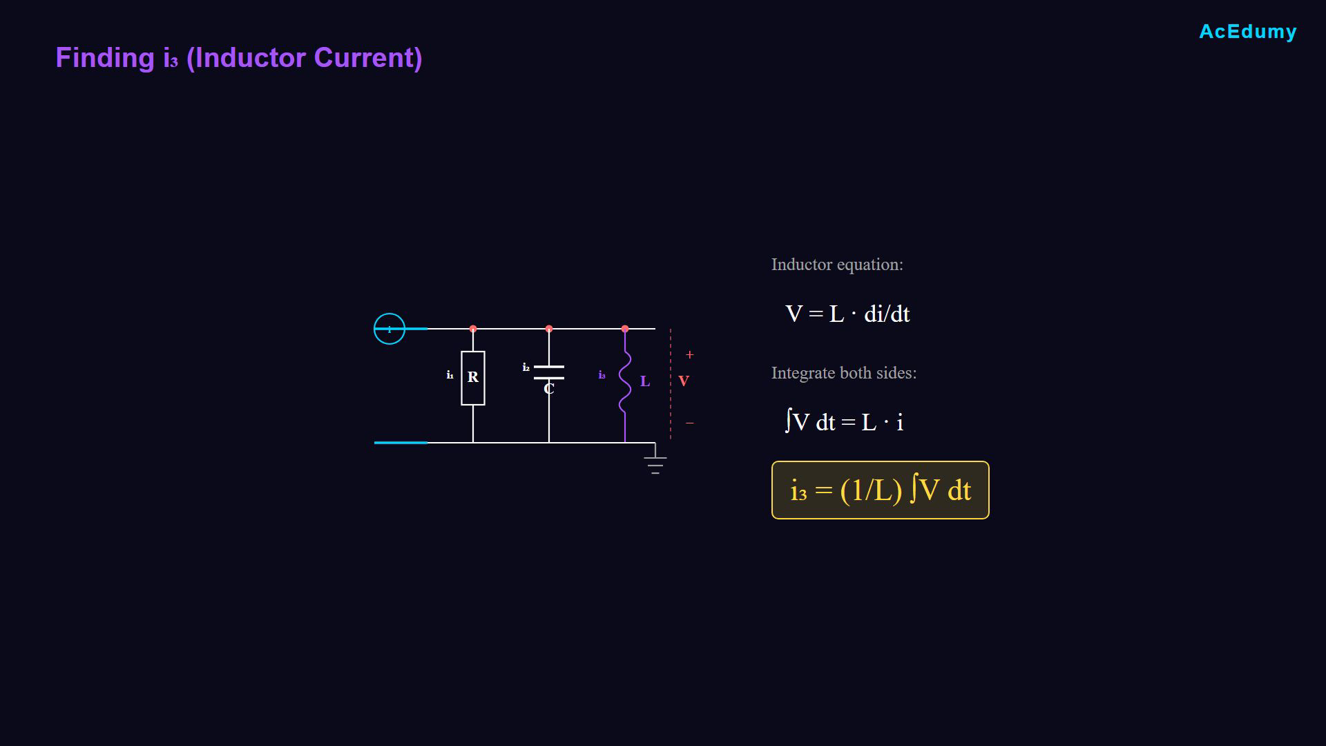
Read branch currents from the positive-voltage node toward ground. The circle on the upper lead labels the external input current; the two left leads form the driving port. Integrals include the inductor initial current. The preference for an equation without integrals applies to this derivation. Express the inductor relation in terms of current.Solve for the inductor branch current.Integrate with respect to time and retain the initial current.Inductor current:Narration transcript
But we want current, not voltage. We need to solve for I3. Taking the integral of both sides with respect to time, the derivative and integral cancel on the right side. This gives us I3 equals 1 over L times the integral of V with respect to time.
12. Combine the branch currents
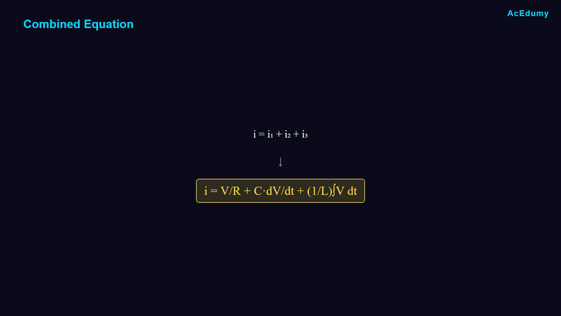
Read branch currents from the positive-voltage node toward ground. The circle on the upper lead labels the external input current; the two left leads form the driving port. Integrals include the inductor initial current. The preference for an equation without integrals applies to this derivation. Use all three branch relations.Combine them in the current balance.The input current equals the sum of branch currents.Current balance:Narration transcript
Now we have all three branch currents. Let's write our complete equation. The main current I equals the sum of all branch currents. V over R plus C times dV over dt plus 1 over L times the integral of V dt.
13. Choose an ordinary differential model
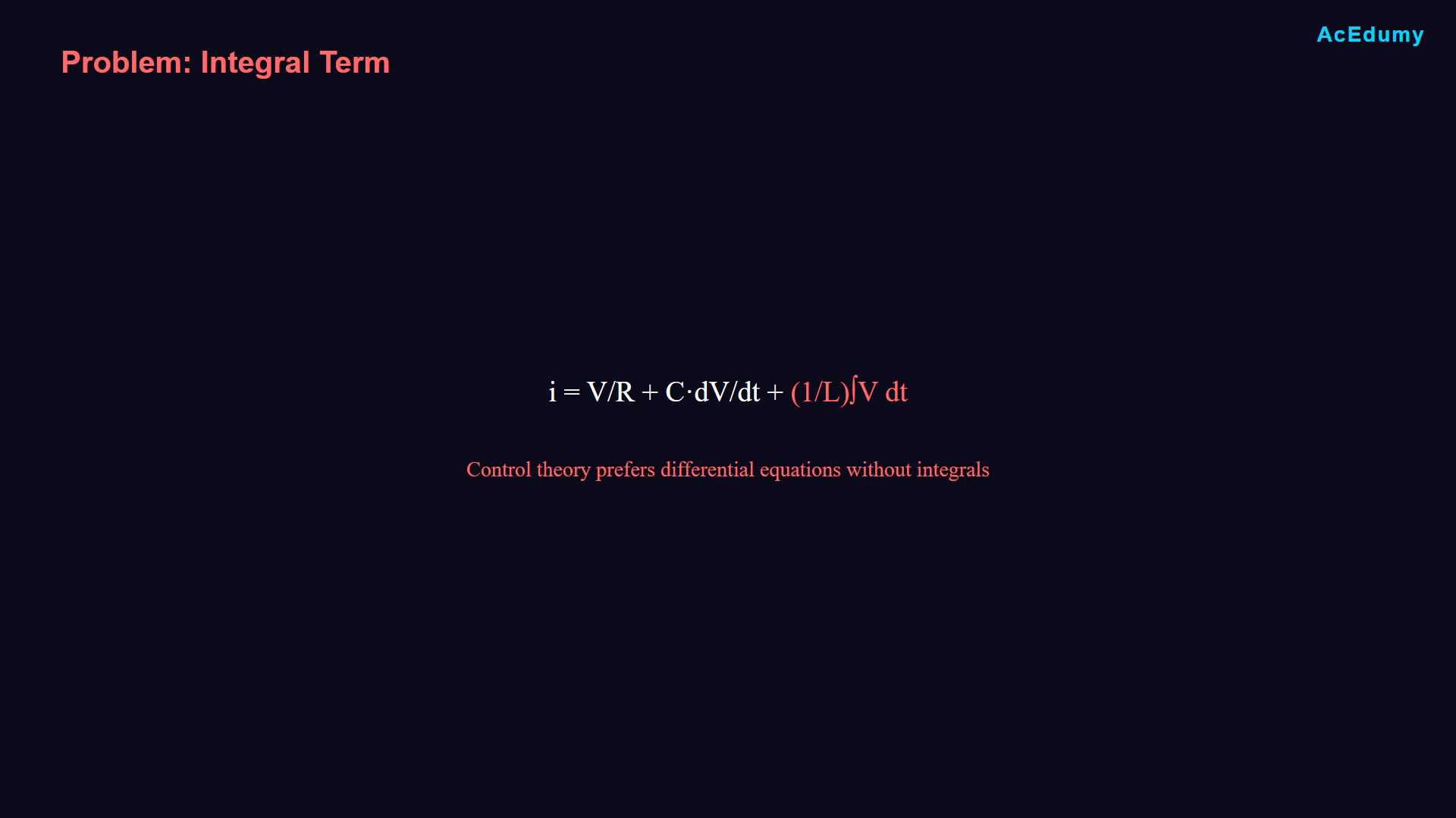
Read branch currents from the positive-voltage node toward ground. The circle on the upper lead labels the external input current; the two left leads form the driving port. Integrals include the inductor initial current. The preference for an equation without integrals applies to this derivation. The current model contains an integral.For this derivation, seek an ordinary differential equation.The integral stores the inductor’s initial-state information.Remove the integral by differentiating the current balance.Narration transcript
There is a problem with this equation. In control theory, we prefer to work with differential equations, not integro-differential equations. That integral term makes analysis more difficult. We need to eliminate it.
14. Differentiate every term
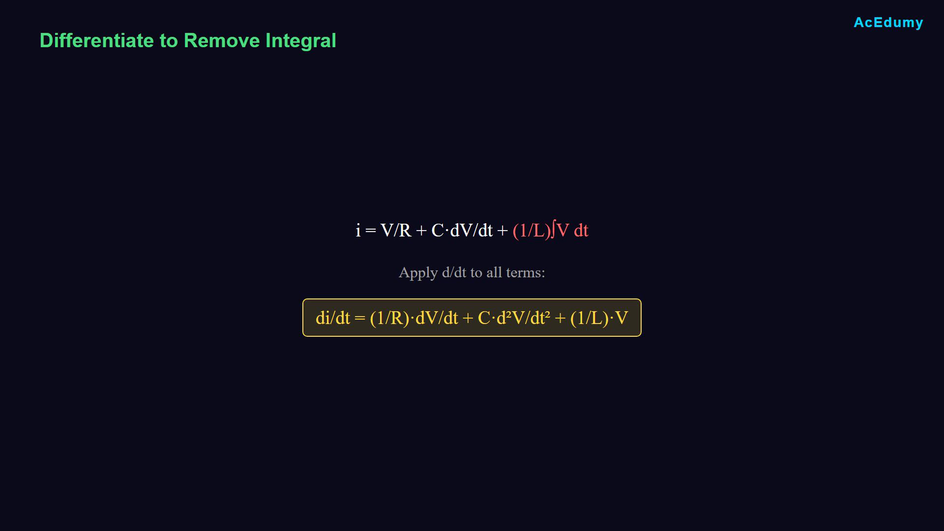
Read branch currents from the positive-voltage node toward ground. The circle on the upper lead labels the external input current; the two left leads form the driving port. Integrals include the inductor initial current. The preference for an equation without integrals applies to this derivation. Differentiate both sides and every term with respect to time.The derivative of the voltage integral returns voltage.Differentiated balance:Narration transcript
The solution is to differentiate the entire equation with respect to time. When we differentiate an integral, they cancel out. Applying the derivative, di over dt equals 1 over r times dv over dt plus c times d squared v over dt squared plus 1 over l times v.
15. Substitute input and output variables
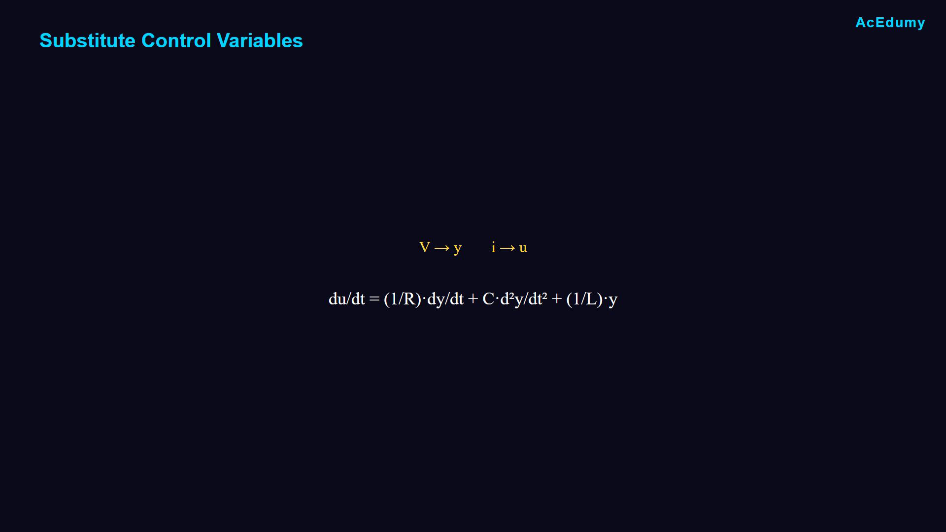
Read branch currents from the positive-voltage node toward ground. The circle on the upper lead labels the external input current; the two left leads form the driving port. Integrals include the inductor initial current. The preference for an equation without integrals applies to this derivation. Use the chosen control variables.Replace voltage by y and input current by u.Control equation:Narration transcript
Now we substitute our control variables. Replace v with y for output and i with u for input. This gives us du over dt equals 1 over r times dy over dt plus c times d squared y over dt squared plus 1 over l times y.
16. Write the second-order plant model
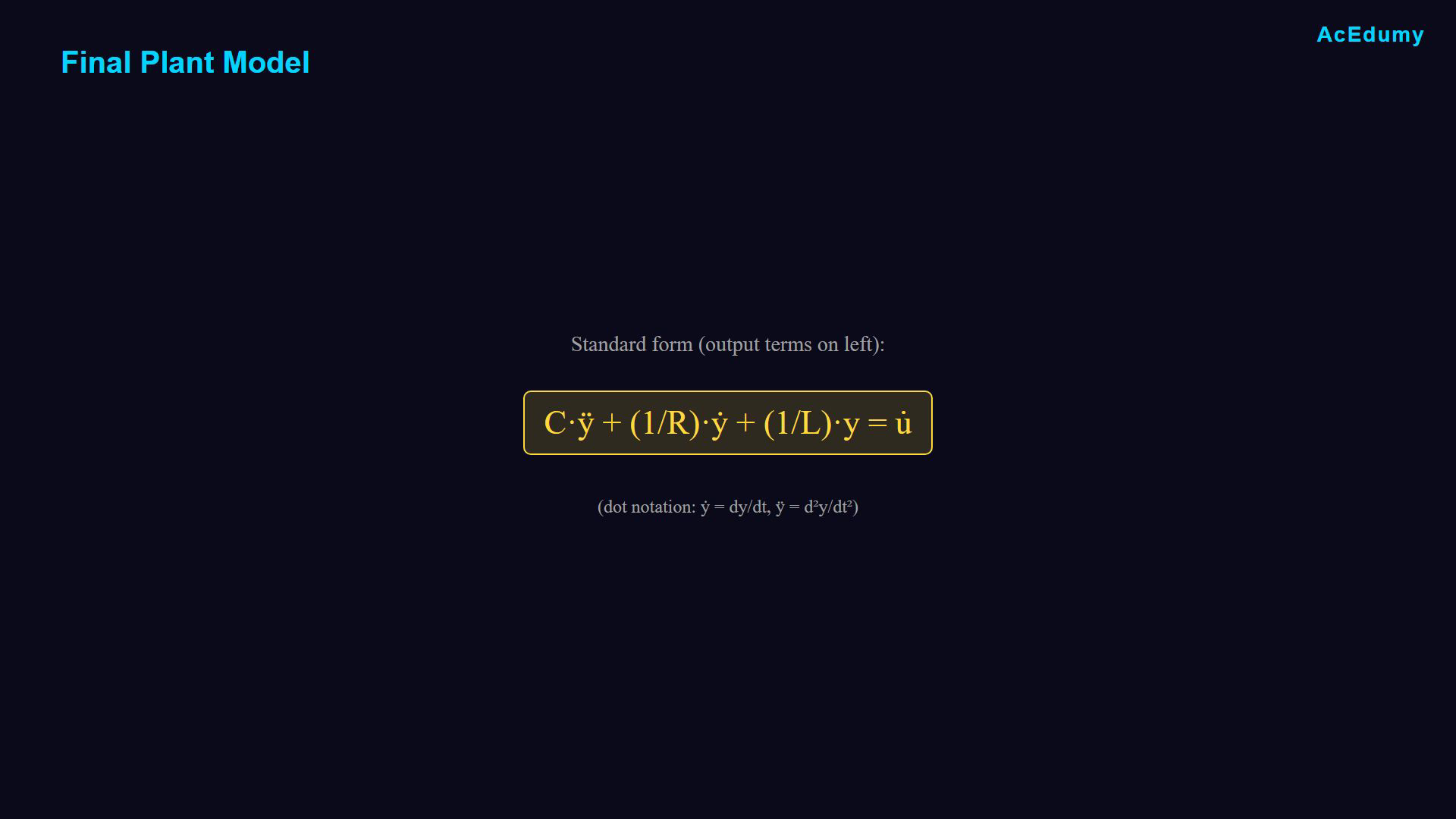
Read branch currents from the positive-voltage node toward ground. The circle on the upper lead labels the external input current; the two left leads form the driving port. Integrals include the inductor initial current. The preference for an equation without integrals applies to this derivation. Plant equation:This is a second-order voltage model with the input-current derivative.Narration transcript
Rearranging to standard form with output terms on the left, C times y double dot plus 1 over R times y dot plus 1 over L times y equals u dot. This second order differential equation is our planned model for the RLC parallel circuit.
17. Review the modeling sequence
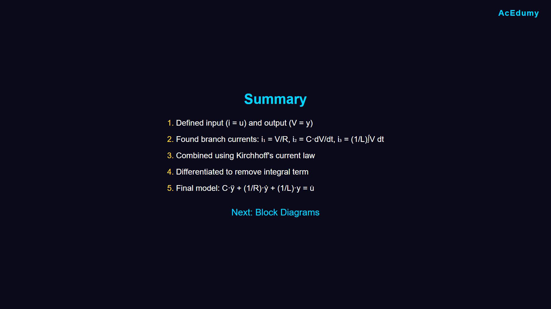
Read branch currents from the positive-voltage node toward ground. The circle on the upper lead labels the external input current; the two left leads form the driving port. Integrals include the inductor initial current. The preference for an equation without integrals applies to this derivation. Review the modeling sequence.Choose current input and voltage output.Write the resistor, capacitor and inductor relations.Combine currents, differentiate and express the result in control variables.Next: construct block diagrams from the equations.The modeling example is complete.Narration transcript
Let's review what we accomplished. We defined the input current and output voltage. We found the current through each component using Ohm's law, capacitor equations, and inductor equations. We combined them using Kirchhoff's law, differentiated to remove the integral, and expressed the final model in standard control form. In the next lesson, we'll learn how to draw block diagrams from these equations. See you then.
Source video: Control Theory #05 - Plant Modeling: RLC Parallel Circuit (5:21)