Circuit Theory 2 · Delta connections and three-phase power
#12 Derive line-current subtraction and calculate balanced RMS power
Derive the balanced delta line current, calculate an inductive 208 V load and distinguish ideal rotating-field intuition from circuit identities.
Question
Analyze an ideal balanced sinusoidal positive-sequence delta load. Three identical impedances connect terminals a-b, b-c and c-a. Reference line currents into the load and branch currents I_ab from a to b, I_bc from b to c and I_ca from c to a. Derive I_a=I_ab-I_ca using I_ab as the zero-angle complex RMS reference; distinguish magnitudes from phasors and the 60-degree common-origin rhombus angle from the 120-degree head-to-tail triangle interior. The square-root-three current factor and 30-degree lag assume positive sequence and these current references. V_p and I_p denote RMS phase magnitudes, not peak values; V_L and I_L are RMS line magnitudes. A delta phase voltage is across one impedance between two lines, not a phase-to-neutral voltage. Derive balanced sinusoidal real power using theta as the load-impedance angle between a branch voltage and that branch's current, not the angle between V_ab and I_a. Calculate V_L=208 V and Z_delta=(30+j15) ohms using exact intermediate values; exact power is 3461.12 W, while the rounded factors in the source give about 3459.12 W (its spoken 3458 W is only approximate); both round to 3.46 kW. The previous wye example used 120 V phase RMS and therefore about 207.846 V line, so comparing it to 208 V gives only approximate equal power. Exact balanced Y-delta terminal equivalence at the same line voltage uses Z_delta=3 Z_Y. For rotating-field intuition assume balanced sinusoidal currents, equal appropriately distributed windings with axes 120 degrees apart in space and an ideal linear magnetic model. Normalized vector values are not tesla; field angular speed is not generally mechanical rotor speed. Stationary stator windings can produce a rotating field, but this does not eliminate mechanical input to a generator or explain every single-phase motor's starting arrangement. Reference images are reviewed cards from this same final. The source delta picture has outward line arrows inconsistent with its KCL convention; its phasor axes have unequal display scales and clipping; numeric raster uses raw single-line notation; source 3D coil and arrow scaling need teaching QA. Those five roles use correct definition/power/summary cards instead, not newly drawn circuit, phasor or 3D diagrams. Original source narration, MP3s and video are unchanged. These visual-detail losses and broad source statements remain manual teaching/publication QA notes. This is an unpublished draft, not wiring instructions.
Written solution and narration transcript(shows the full solution)
Below are all the lines written in the notebook together with the full narration transcript.
1. Recall the balanced wye relations
Reference card from the existing English final, not a newly rendered circuit, phasor or 3D animation. Line currents point into the load by definition; detailed derivations and readable formulas are in the notebook lines. Recall a balanced ABC wye set, with RMS phase magnitudes:Now use a delta (Δ) load with the same positive phase sequence.Three identical impedances connect a to b, b to c, and c to a.The delta load has no shared neutral node; this ideal circuit description is not wiring advice.The square-root factor now relates balanced current magnitudes:Narration transcript
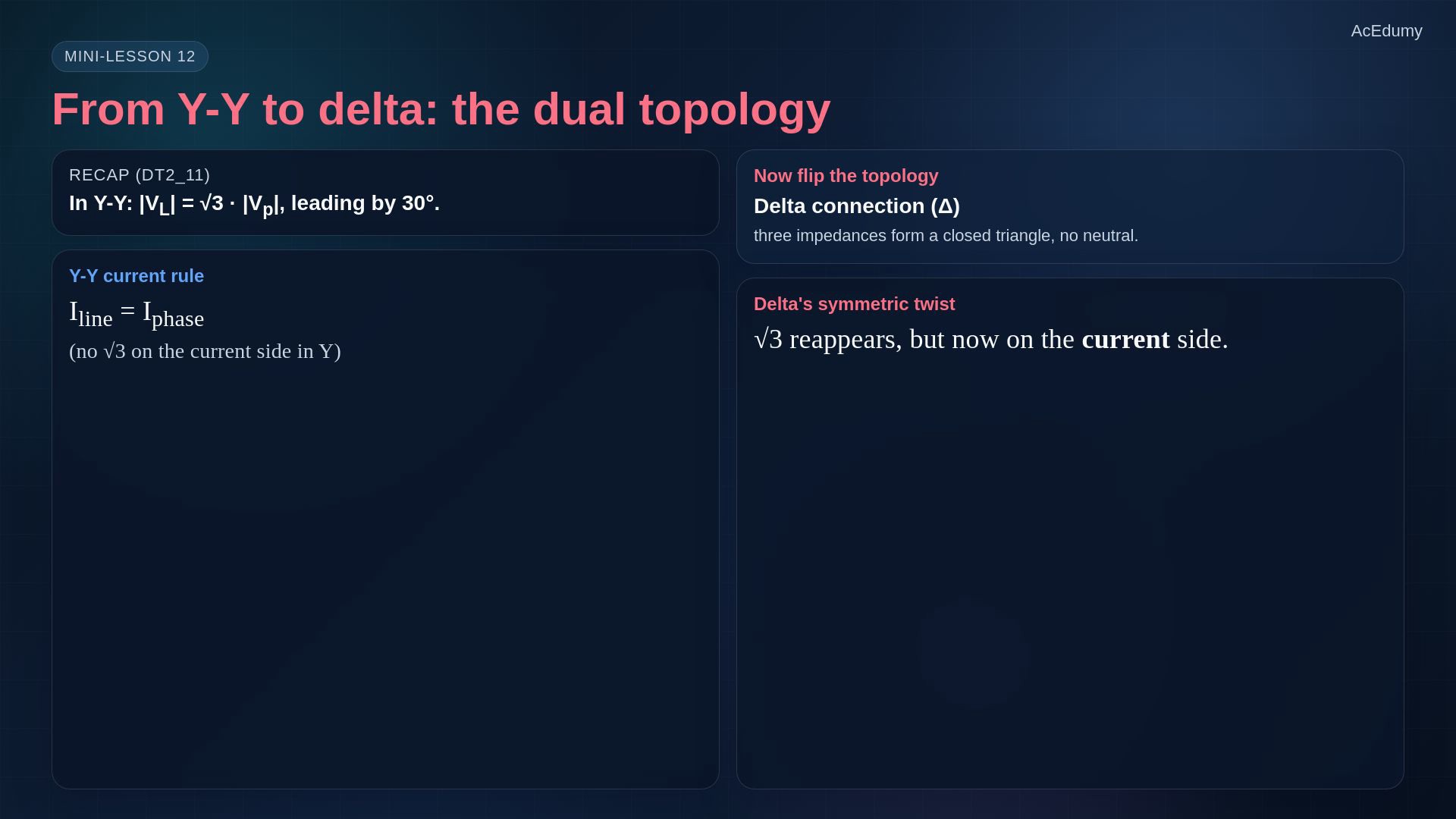
In the previous lesson we connected three balanced phasors to a Y-Y circuit and discovered that the line voltage equals square root of three times the phase voltage. Now we flip the topology to delta. Three impedances form a closed triangle. There is no neutral. The square root of three factor reappears, but this time on the current side.
2. Define delta terminals and current directions
Reference card from the existing English final, not a newly rendered circuit, phasor or 3D animation. Line currents point into the load by definition; detailed derivations and readable formulas are in the notebook lines. Use the reviewed branch-direction card; the original circuit picture has outward line arrows inconsistent with the inward reference used here.Three equal impedances form the closed delta loop:There is no shared central node in this delta load.Define each line current into its load terminal; branch currents use the cyclic directions shown in the card.Each branch is connected across two lines, so its RMS voltage magnitude is:The branch from a to b uses the same ordered line-voltage reference:Narration transcript
Here is the standard delta connection. Three impedances Z delta sit between the three line terminals a, b, and c, forming a closed triangle. Notice what is missing -- there is no neutral point and no fourth wire. Each impedance carries a phase current, and each line carries a line current. The fundamental difference from Y is that in delta, the phase voltage equals the line voltage. The same V a b that drives the line in Y now drives one entire impedance arm of the delta.
3. Fix a positive-sequence branch-current reference
Reference card from the existing English final, not a newly rendered circuit, phasor or 3D animation. Line currents point into the load by definition; detailed derivations and readable formulas are in the notebook lines. Branch references are Iab from a to b, Ibc from b to c, and Ica from c to a.Assume balanced sinusoidal terminal voltages and three identical impedances. Then branch currents have equal RMS magnitude Ip and positive ABC spacing.Narration transcript
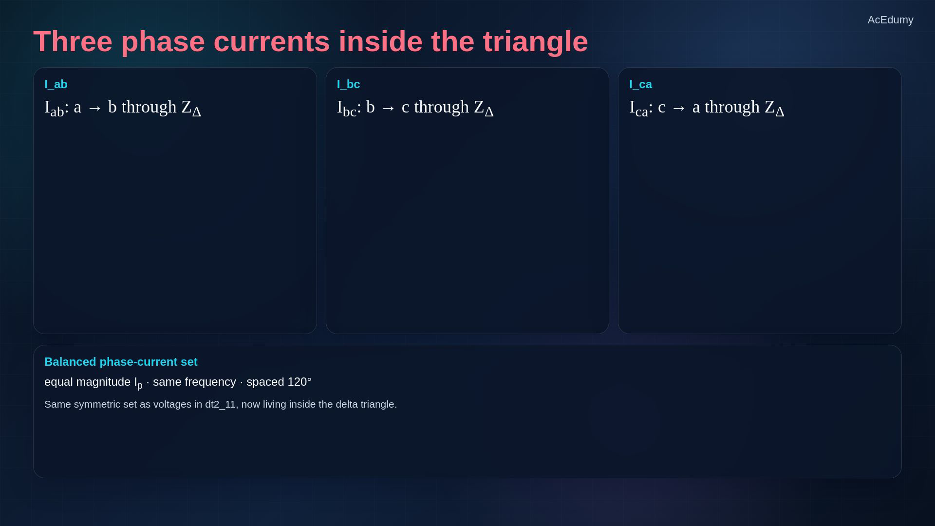
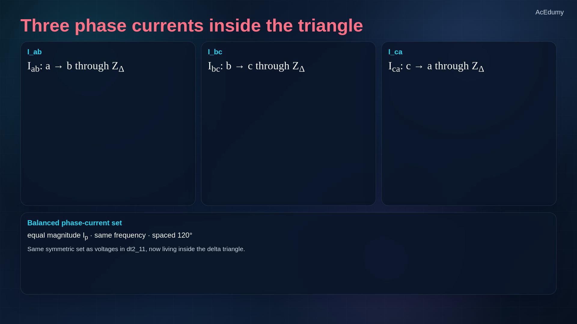
In delta, the three phase currents flow inside the triangle: I a b flows from a to b through the first impedance, I b c from b to c, and I c a from c to a. For a balanced positive sequence load, these three currents form their own balanced set, equal in magnitude and spaced one hundred twenty degrees apart -- just like the voltages were in the previous lesson.
4. Apply KCL with line current into the load
Reference card from the existing English final, not a newly rendered circuit, phasor or 3D animation. Line currents point into the load by definition; detailed derivations and readable formulas are in the notebook lines. Define Ia as entering the delta load at terminal a.At a, I_a and I_ca enter while I_ab leaves:Rearrange KCL without reversing a current reference:The reference image is the KCL card, not a new phasor diagram; derive the subtraction in the next lines.Narration transcript
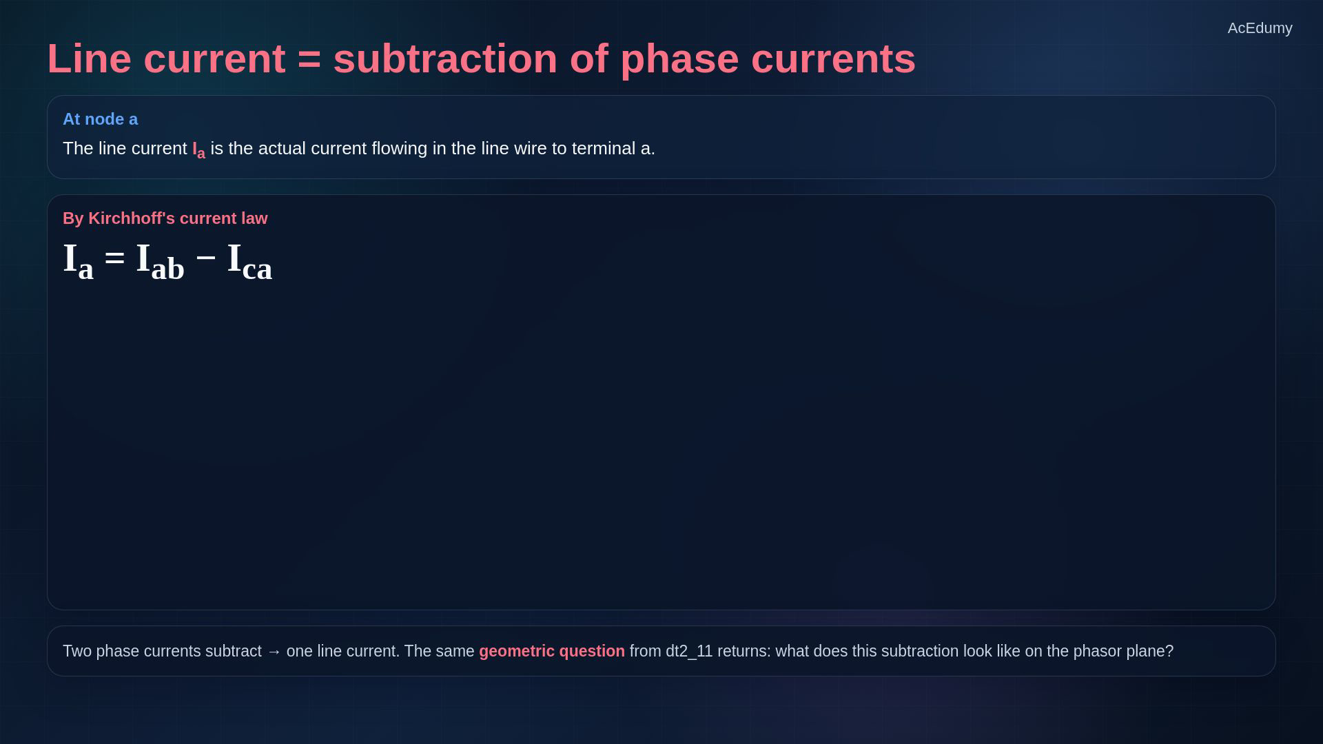
The line current I a is the current actually flowing through the wire connected to terminal a. By Kirchhoff's current law applied at node a, the current flowing in equals the currents leaving -- so I a equals I a b minus I c a. Two phase currents subtract to give one line current. The same geometric question returns -- what does this subtraction look like on the phasor plane?
5. Subtract phase-current phasors
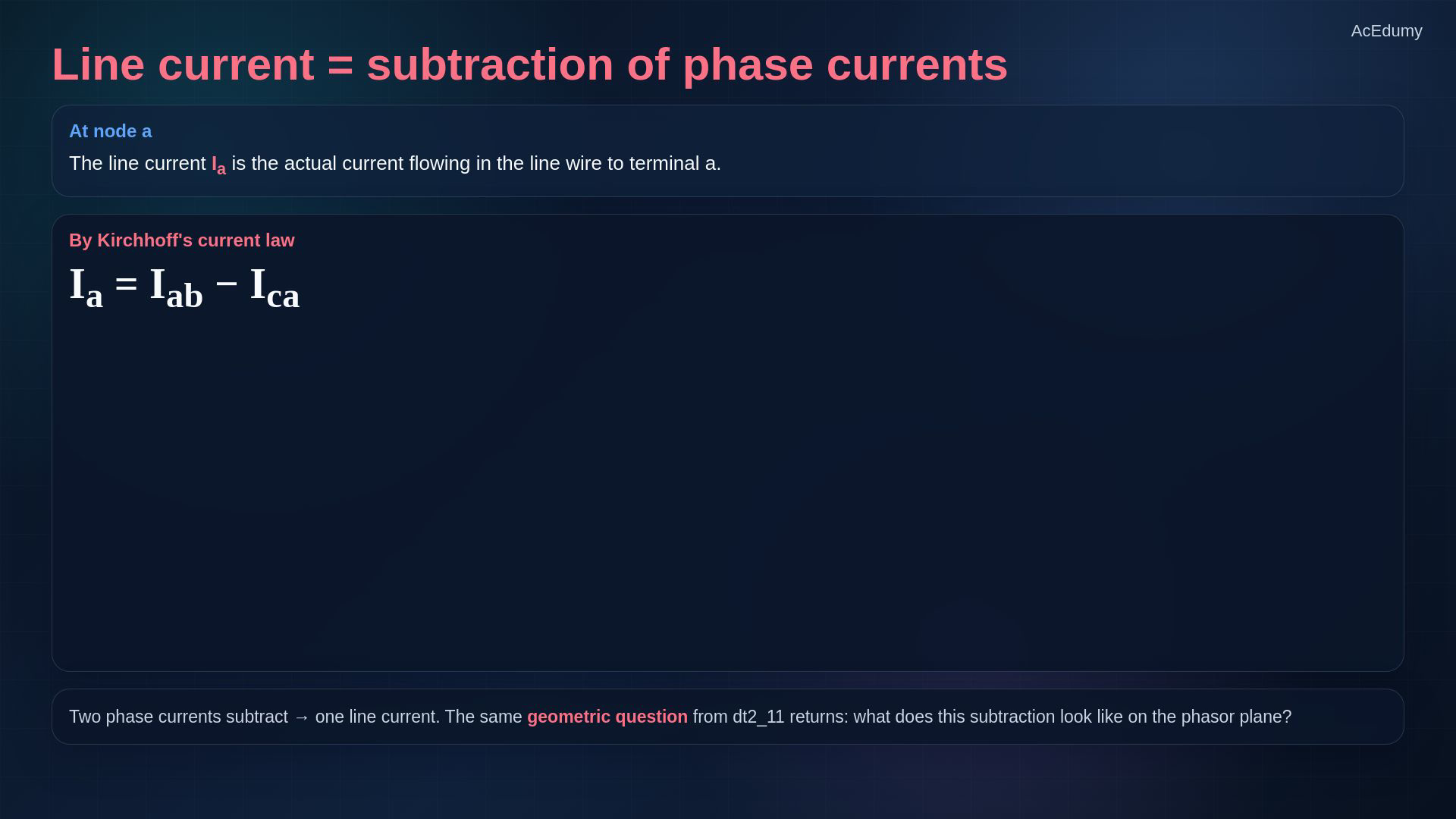
Reference card from the existing English final, not a newly rendered circuit, phasor or 3D animation. Line currents point into the load by definition; detailed derivations and readable formulas are in the notebook lines. Use fixed complex RMS phasors, a positive sequence and inward line-current references.Choose the branch current as the zero-angle reference:The c-to-a branch leads this reference by 120°:Negating a phasor rotates it by 180°:The two equal vectors have a 60° common-origin separation; the corresponding head-to-tail triangle has a 120° interior angle.Subtract in rectangular coordinates:Compute the magnitude from perpendicular components:The real part is positive and imaginary part negative, so the result lies in quadrant IV:For these stated references:Narration transcript
Watch the construction. I a b sits along the reference axis. I c a sits at plus one hundred twenty degrees. To form I a equals I a b minus I c a, we flip I c a to its negative, swinging it down to minus sixty degrees, and add it tip-to-tail to I a b. The two equal-length vectors form a rhombus. The diagonal from the origin to the far corner is exactly I a. With both sides of length I phase and an internal angle of sixty degrees, the cosine rule gives a diagonal length of square root of three times I phase. The diagonal lands at minus thirty degrees. So I a lags I a b by thirty degrees, with magnitude root three I phase.
6. Separate the current magnitude and angle
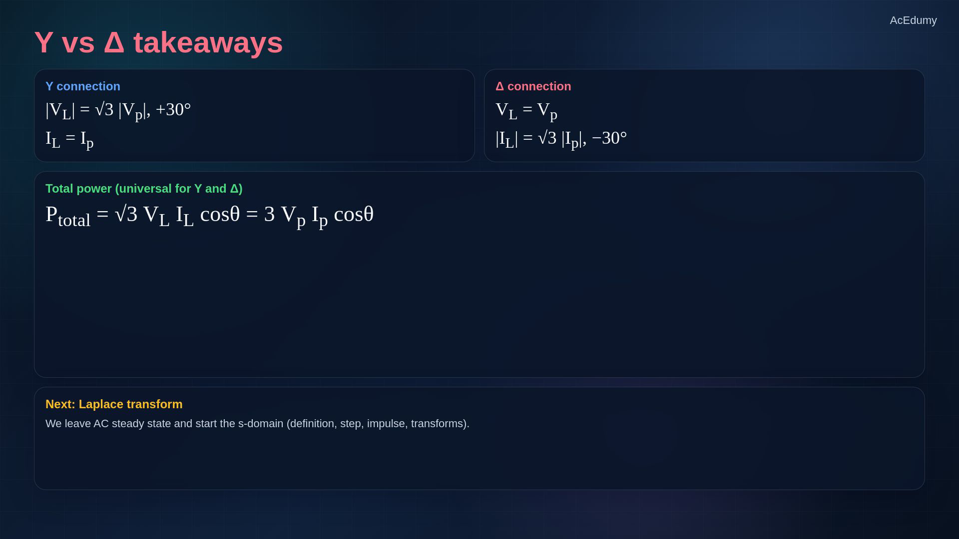
Reference card from the existing English final, not a newly rendered circuit, phasor or 3D animation. Line currents point into the load by definition; detailed derivations and readable formulas are in the notebook lines. Separate the RMS magnitude relation from its phase-angle condition.For a balanced delta load:With I_ab as reference, the three line-current angles are:The 30° lag is relative to the corresponding branch current, not directly to its branch voltage.In positive sequence, wye gives a 30° line-voltage lead; delta gives a 30° line-current lag under the chosen references.Narration transcript
Here is the symmetric headline. In delta, the line current magnitude is square root of three times the phase current magnitude, but it lags by thirty degrees instead of leading. The other two line currents I b and I c follow the same pattern, each rotated by another one hundred twenty degrees. Three line currents form a second balanced star -- same root three magnitude, rotated minus thirty degrees from the phase star. This is the mirror image of the Y-Y voltage result.
7. Relate branch voltage to line voltage
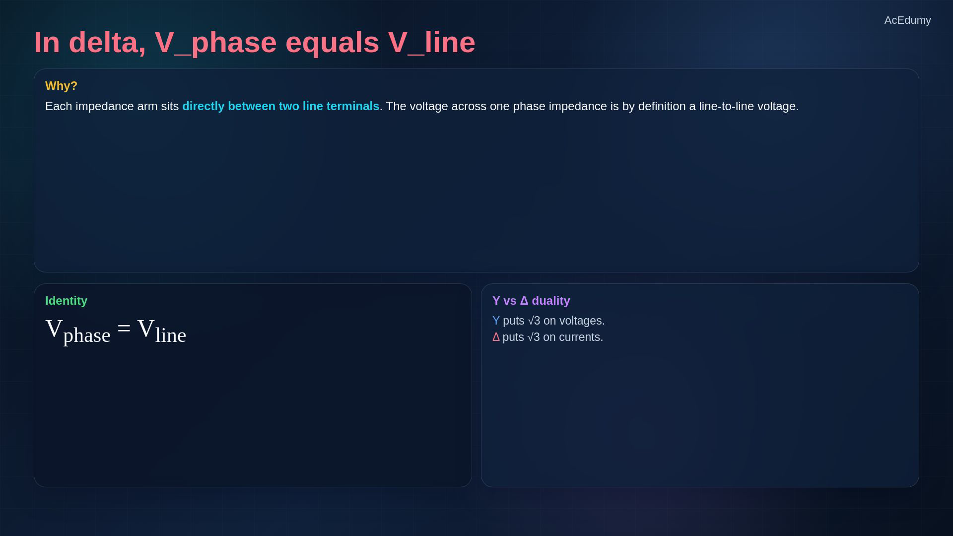
Reference card from the existing English final, not a newly rendered circuit, phasor or 3D animation. Line currents point into the load by definition; detailed derivations and readable formulas are in the notebook lines. Now identify the voltage across each delta branch.Each impedance arm is connected directly between two line terminals.The branch and line-to-line voltages use the same ordered pair of terminals.Delta branch and line RMS magnitudes are equal:Do not multiply delta line voltage by a square-root factor to obtain its branch voltage.In balanced systems, wye introduces the square root of three in voltage magnitudes and delta in current magnitudes.Narration transcript
Now look at the voltage side in delta. Each impedance arm sits directly between two line terminals. So the voltage across one phase impedance is exactly a line-to-line voltage. In delta, V phase equals V line. There is no square root of three on the voltage side. Delta and Y are duals: Y puts root three on voltages, delta puts root three on currents.
8. Use balanced sinusoidal RMS power
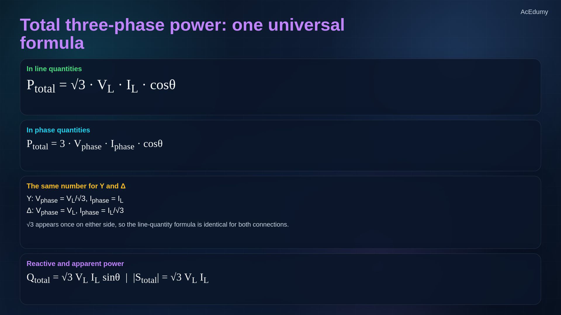
Reference card from the existing English final, not a newly rendered circuit, phasor or 3D animation. Line currents point into the load by definition; detailed derivations and readable formulas are in the notebook lines. Assume balanced sinusoidal voltages and currents; all voltage and current magnitudes below are RMS.Average real power in line quantities:The same result follows from summing the three equal phase powers:For delta substitute the current relation:θ is the load-impedance angle between a branch voltage and its own current, not directly between Vab and Ia. The formula is not universal for arbitrary unbalanced or nonsinusoidal loads.Narration transcript
Now the most useful result of all. Total three-phase average power can be written in line quantities as square root of three times V line times I line times cosine theta, where theta is the impedance angle. This formula works for both Y and delta connections -- exactly the same. Although V phase and I phase look different in Y versus delta, the line quantities V L and I L combine in such a way that the total power formula is universal. It does not depend on which connection you choose.
9. Calculate the 208 V delta load
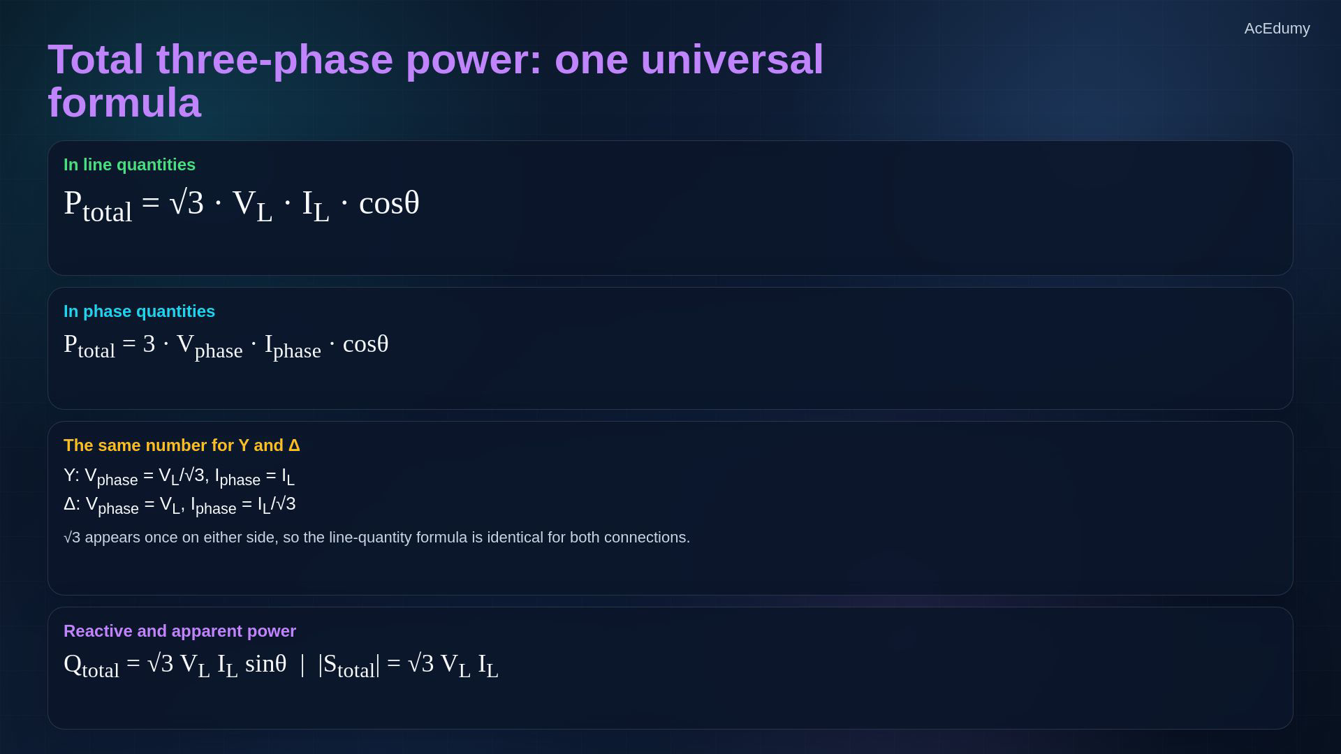
Reference card from the existing English final, not a newly rendered circuit, phasor or 3D animation. Line currents point into the load by definition; detailed derivations and readable formulas are in the notebook lines. Use the original balanced delta example; keep exact values until the final rounding.The line-voltage RMS magnitude is:Each inductive branch impedance is:Its magnitude is:The impedance angle is:In delta the branch has the full line voltage:Branch current lags its own branch voltage by θ; its RMS magnitude is:The line-current RMS magnitude is:The inductive load has lagging power factor:Using the rounded source factors gives about 3459 W; keeping exact values gives 3461.12 W. Both round to:The earlier wye example used 120 V per phase, so its line voltage was about 207.85 V, rounded to 208 V here; equality of power is approximate in that comparison.Exact balanced terminal equivalence at the same line voltage requires:Narration transcript
Let us put numbers on it. Take a delta-connected load with line voltage two hundred and eight volts r m s. Each leg of the delta is Z delta equals thirty plus j fifteen ohms. First, the magnitude and angle of Z delta: the magnitude is square root of one thousand one hundred twenty five, which is thirty three point five four ohms. The angle is arctangent of fifteen over thirty, which is twenty six point five seven degrees. Phase current: in delta, V phase equals V line equals two hundred and eight volts. So I phase equals two hundred and eight divided by thirty three point five four, giving six point two zero amperes r m s, lagging by twenty six point five seven degrees. Line current: in delta, I line equals root three times I phase, which is one point seven three two times six point two zero, giving ten point seven four amperes r m s. Cosine of twenty six point five seven degrees is zero point eight nine four. Total power: root three times two hundred and eight times ten point seven four times zero point eight nine four equals about three thousand four hundred fifty eight watts, or three point four six kilowatts. Compare with the Y-Y example from the previous lesson -- same line voltage, same total power. Y or delta, the externally measurable behavior is identical when the loads are equivalent.
10. Interpret the ideal rotating-field model
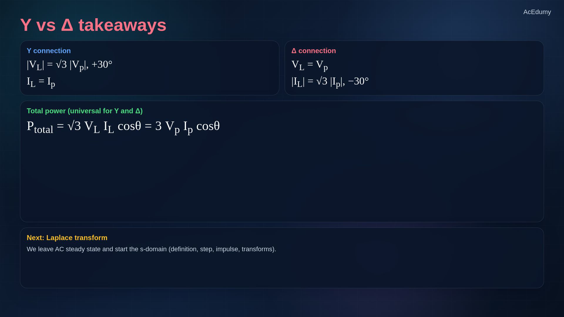
Reference card from the existing English final, not a newly rendered circuit, phasor or 3D animation. Line currents point into the load by definition; detailed derivations and readable formulas are in the notebook lines. Now interpret the rotating-field idea as an ideal model, not a literal engineering winding design.Use equal sinusoidal currents separated by 120° in time and equal effective coil axes separated by 120° in space.In the ideal linear model their field vectors sum to a constant-magnitude vector rotating at constant angular speed.The field can rotate with stationary windings; this does not assert that a generator supplies electrical power without mechanical input.The reference still is the summary card, not the source 3D coil geometry. Field speed and mechanical rotor speed are not generally identical; single-phase motor starting also needs separate treatment.Narration transcript
Here is why three-phase systems matter so much. Three currents, each shifted by one hundred twenty degrees in time, flow through three coils, each placed one hundred twenty degrees apart in space. Their magnetic vectors add up to a single vector that rotates in the stator at constant speed. No mechanical motion, only electrical phase shifts, produce a smoothly rotating magnetic field. This is the heart of every induction motor and every three-phase generator.
11. Keep topology and balance conditions explicit
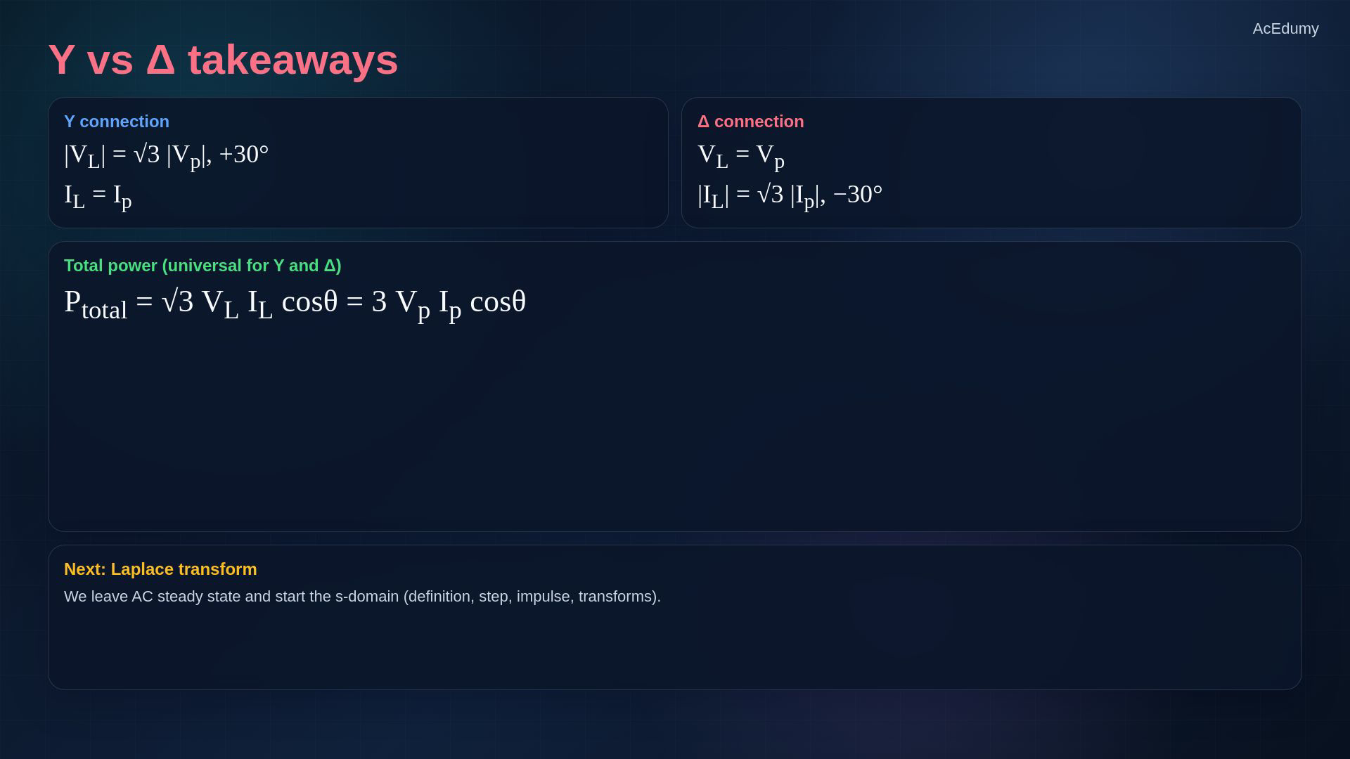
Reference card from the existing English final, not a newly rendered circuit, phasor or 3D animation. Line currents point into the load by definition; detailed derivations and readable formulas are in the notebook lines. Keep the balanced delta result and its reference directions together.RMS relations for delta:For balanced sinusoidal Y or Δ loads:Rotating-field intuition additionally needs appropriate spatial windings; electrical phase spacing alone is not a machine model.Next: the Laplace transform definition, unit step, impulse and basic transform pairs.Narration transcript
Three takeaways for delta. Line current is root three times phase current, lagging by thirty degrees, while line voltage equals phase voltage. Total power is root three V line I line cosine theta -- the same universal formula whether the load is Y or delta. And the same three-phase symmetry that gave us clean equations also gives us rotating magnetic fields in machines. Next we leave AC steady state and start the Laplace transform.
Source video: Circuit Theory-2 #12 | Delta Connections and Three-Phase Power (7:55)