Digital Design · Voltage Ranges, Logic Bits and Input Limits
#01 Classify three voltages and calculate their headroom to the guaranteed LOW and HIGH limits
Connect physical voltage ranges to bits, classify three input measurements and distinguish measurement headroom from guaranteed gate-to-gate noise margins.
Question
Use the positive-logic convention of this introductory example: low voltage represents binary zero and high voltage represents binary one. Physical voltages are continuous even when the logic abstraction uses two values. The supplied illustrative input has a3.3V supply, maximum guaranteed LOW input V_ILmax=0.8V and minimum guaranteed HIGH input V_IHmin=2.0V. Classify measured inputs0.4V,1.2V and2.8V, calculate the indicated distances to the relevant limits, and explain how bits, logic gates, arithmetic/selection blocks, registers and state machines form larger digital systems. These are supplied example limits, not universal thresholds for every3.3V logic family. No particular component data sheet, driver output guarantees, propagation delays or setup/hold times are supplied. Interpret the voltage bands within the illustrated normal range0 through3.3V. A voltage at or below0.8V is guaranteed LOW, and a voltage at or above2.0V is guaranteed HIGH. The equal endpoints are included by the stated V_ILmax and V_IHmin definitions. The open interval between0.8V and2.0V has no guaranteed binary interpretation. Do not infer that the exact physical switching threshold is either specified boundary, that the input certainly oscillates, or that a third stable binary value exists. Do not round the middle value to the nearest bit. In particular1.2V can produce different logical behavior in devices consistent with these same guarantees. A finite-speed transition normally crosses intermediate voltages; avoid relying on that region at a sampling instant or as a steady input, and obey the relevant device's transition-time and timing requirements. The phrase avoid the middle does not mean a physical signal can jump instantaneously over every intermediate voltage. Values below ground or above the illustrated supply range are not authorized operating conditions by this example. For0.4V, the guaranteed result is LOW because0.4<0.8. The upward voltage headroom to the LOW input limit is M_L=V_ILmax-0.4V=0.4V. An upward perturbation of exactly0.4V reaches0.8V and still meets the limit; a slightly larger perturbation enters the undefined band and loses the LOW guarantee, without necessarily switching HIGH. For2.8V, the guaranteed result is HIGH because2.8>2.0. The downward voltage headroom is M_H=2.8V-V_IHmin=0.8V. A downward perturbation of exactly0.8V reaches2.0V and still meets the HIGH limit; a slightly larger drop enters the undefined band. These are directional distances to the logic thresholds. They are not guarantees for arbitrarily signed noise that might exceed electrical supply/absolute-maximum limits. The third measured value1.2V lies strictly between the two input limits and is undefined by the given binary specification. The narration calls these distances low and high noise margins. In this example they mean headroom from the measured LOW and HIGH levels, as the figure's arrows show. Conventional worst-case static gate-to-gate margins require a driving device's guaranteed outputs: NM_L=V_ILmax-V_OLmax and NM_H=V_OHmin-V_IHmin. The measured0.4V and2.8V were not supplied as V_OLmax and V_OHmin guarantees, so the computed0.4V and0.8V cannot establish those worst-case interface margins for all loads, devices or temperatures. Do not silently relabel measurements as guaranteed driver specifications. This distinction preserves the source arithmetic while making its scope precise. For valid binary input a, an ideal inverter outputs1-a. For two inputs a,b, AND outputs a*b and OR outputs a+b-a*b in ordinary arithmetic restricted to a,b in{0,1}. In Boolean notation a+b often denotes OR; it is not unrestricted real addition. The two-input truth rows(a,b)=(0,0),(0,1),(1,0),(1,1) give AND outputs0,0,0,1 and OR outputs0,1,1,1. For more than two inputs, AND is HIGH exactly when all are HIGH, while OR is HIGH when at least one is HIGH. The source's turns on means its logical output is HIGH, not a statement that every physical transistor conducts or that a gate has zero delay. The figure contains separate gate symbols, not a connected circuit to analyze. Abstraction of voltage does not remove the timing and electrical assumptions that make each input bit valid. Multiplexers select among data inputs, adders compute arithmetic, registers store bits, and finite-state machines use stored state and combinational decisions to control sequences. The hierarchy is conceptual, not a claim that a bit is a separate threshold-comparator module or that each larger block contains exactly one of each smaller block. A processor and memory organize many such blocks. Keep the answer tied to the given voltage example and introductory logic rules.
Written solution and narration transcript(shows the full solution)
Below are all the lines written in the notebook together with the full narration transcript.
1. From voltage to a logic decision
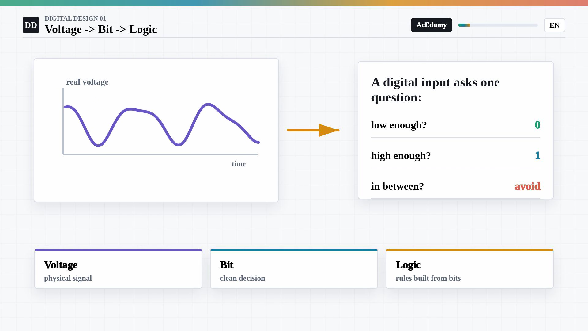
The example uses a three point three volt supply, a maximum guaranteed LOW input of zero point eight volts and a minimum guaranteed HIGH input of two volts. The displayed margins are distances from the given measured inputs to these limits. Equality belongs to the guaranteed ranges. Welcome to digital design.The first surprise is that digital systems are not made of abstract zeros and ones floating in space.They are made of real voltages, moving through real wires.In the positive-logic convention used here, a low voltage range represents zero.A high voltage range represents one.A digital abstraction assigns logic values to allowed analog voltage ranges.Follow the abstraction from voltages to bits, then logic gates and larger digital systems.Narration transcript
Welcome to digital design. The first surprise is that digital systems are not made of abstract zeros and ones floating in space. They are made of real voltages, moving through real wires. A zero is usually a low voltage range. A one is usually a high voltage range. Digital design begins when we agree to treat messy analog voltage as a clean decision. Today we build that agreement: voltage becomes a bit, bits feed logic gates, and gates become the building blocks of a computer.
2. Use two guaranteed input limits
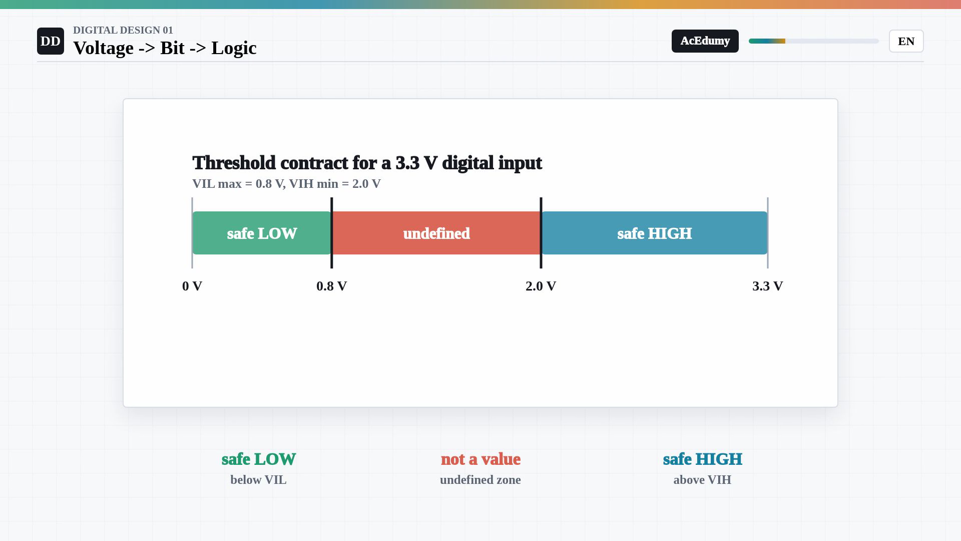
The example uses a three point three volt supply, a maximum guaranteed LOW input of zero point eight volts and a minimum guaranteed HIGH input of two volts. The displayed margins are distances from the given measured inputs to these limits. Equality belongs to the guaranteed ranges. Use guaranteed input-voltage limits.The example input does not require exactly zero volts or exactly three point three volts.Use the specified low and high input limits.A voltage below the low limit is guaranteed to be read as zero; the example also includes equality.A voltage above the high limit is guaranteed to be read as one; the example also includes equality.Between the two input limits, a logic value is not guaranteed by the specification.The undefined region is not a third valid binary value.Do not rely on a sampled or steady input remaining in the undefined region.Narration transcript
Here is the core contract. The input does not ask for exactly zero volts or exactly 3.3 volts. Instead it uses thresholds. Below the low threshold, the input is accepted as zero. Above the high threshold, it is accepted as one. Between those two thresholds there is a forbidden or undefined zone. That middle zone is not a third logic value. It is a warning sign: do not design a circuit that depends on a voltage landing there.
3. Apply NOT, AND and OR rules
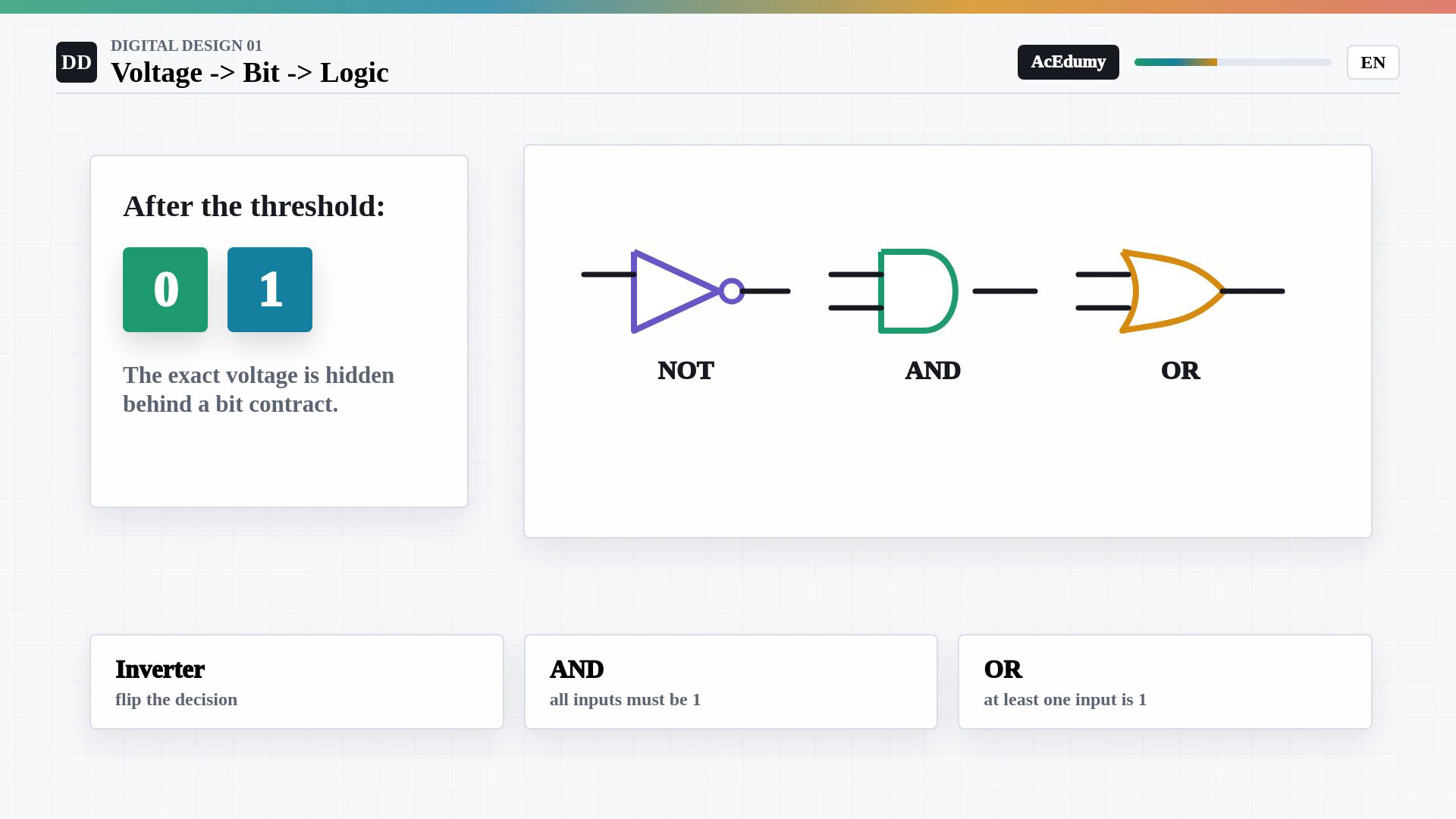
The example uses a three point three volt supply, a maximum guaranteed LOW input of zero point eight volts and a minimum guaranteed HIGH input of two volts. The displayed margins are distances from the given measured inputs to these limits. Equality belongs to the guaranteed ranges. Within valid voltage and timing conditions, use binary logic without tracking every analog detail.An ideal combinational logic gate maps input bits to an output bit.An inverter complements a valid binary input:For binary inputs, AND is high exactly when every input is high.For binary inputs, OR is high exactly when at least one input is high.Compose reliable logic rules while keeping their underlying electrical and timing conditions satisfied.Narration transcript
Once the threshold decision is made, the circuit can forget the exact voltage for a while and think in bits. A logic gate is a tiny rule machine for bits. An inverter turns zero into one and one into zero. An AND gate turns on only when all its inputs are one. An OR gate turns on when at least one input is one. The deep idea is abstraction: we hide voltage details behind a bit contract, then build bigger rules out of small reliable rules.
4. Classify three example voltages
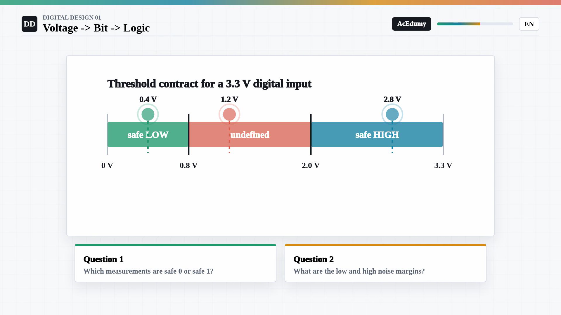
The example uses a three point three volt supply, a maximum guaranteed LOW input of zero point eight volts and a minimum guaranteed HIGH input of two volts. The displayed margins are distances from the given measured inputs to these limits. Equality belongs to the guaranteed ranges. Classify three measured input voltages using the supplied example limits.Illustrative supply voltage:Maximum guaranteed LOW input, including equality:Minimum guaranteed HIGH input, including equality:Measured inputs:Identify the guaranteed LOW, guaranteed HIGH and undefined measurements.Narration transcript
Now let us solve a real-style threshold example. Suppose a 3.3 volt digital input has two limits. V I L max is 0.8 volts, so anything at 0.8 volts or below is safely low. V I H min is 2.0 volts, so anything at 2.0 volts or above is safely high. Three measurements arrive at the input: 0.4 volts, 1.2 volts, and 2.8 volts. Which ones are safe zeros or ones, and which one should make us nervous?
5. Calculate headroom to each limit
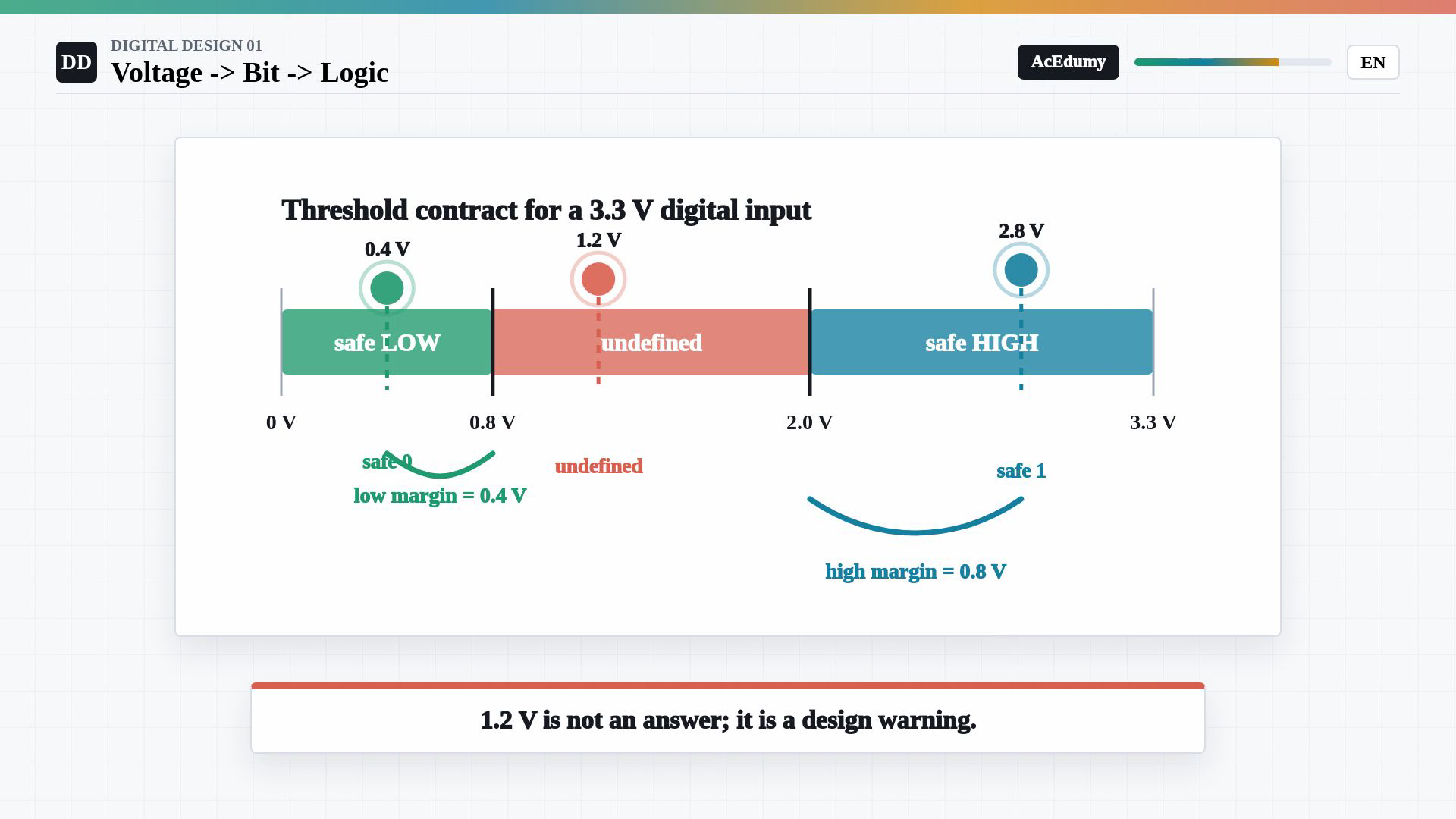
The example uses a three point three volt supply, a maximum guaranteed LOW input of zero point eight volts and a minimum guaranteed HIGH input of two volts. The displayed margins are distances from the given measured inputs to these limits. Equality belongs to the guaranteed ranges. First measured input:It is below the maximum guaranteed LOW input, so it represents zero.Upward headroom from this LOW measurement:Second checked input:It is above the minimum guaranteed HIGH input, so it represents one.Downward headroom from this HIGH measurement:The remaining input, one point two volts, is strictly between zero point eight and two volts.Neither a LOW nor a HIGH interpretation is guaranteed for that measurement.An undefined sampled or steady input requires design attention; do not assign it a reliable bit from these limits alone.Narration transcript
Start with 0.4 volts. It is below 0.8 volts, so it is a safe zero. Its low noise margin is 0.8 minus 0.4, which is 0.4 volts. Now 2.8 volts. It is above 2.0 volts, so it is a safe one. Its high noise margin is 2.8 minus 2.0, which is 0.8 volts. But 1.2 volts sits between 0.8 and 2.0. That is not a safe zero and not a safe one. In a digital design review, that value is a bug report, not an answer.
6. Build successive layers of abstraction
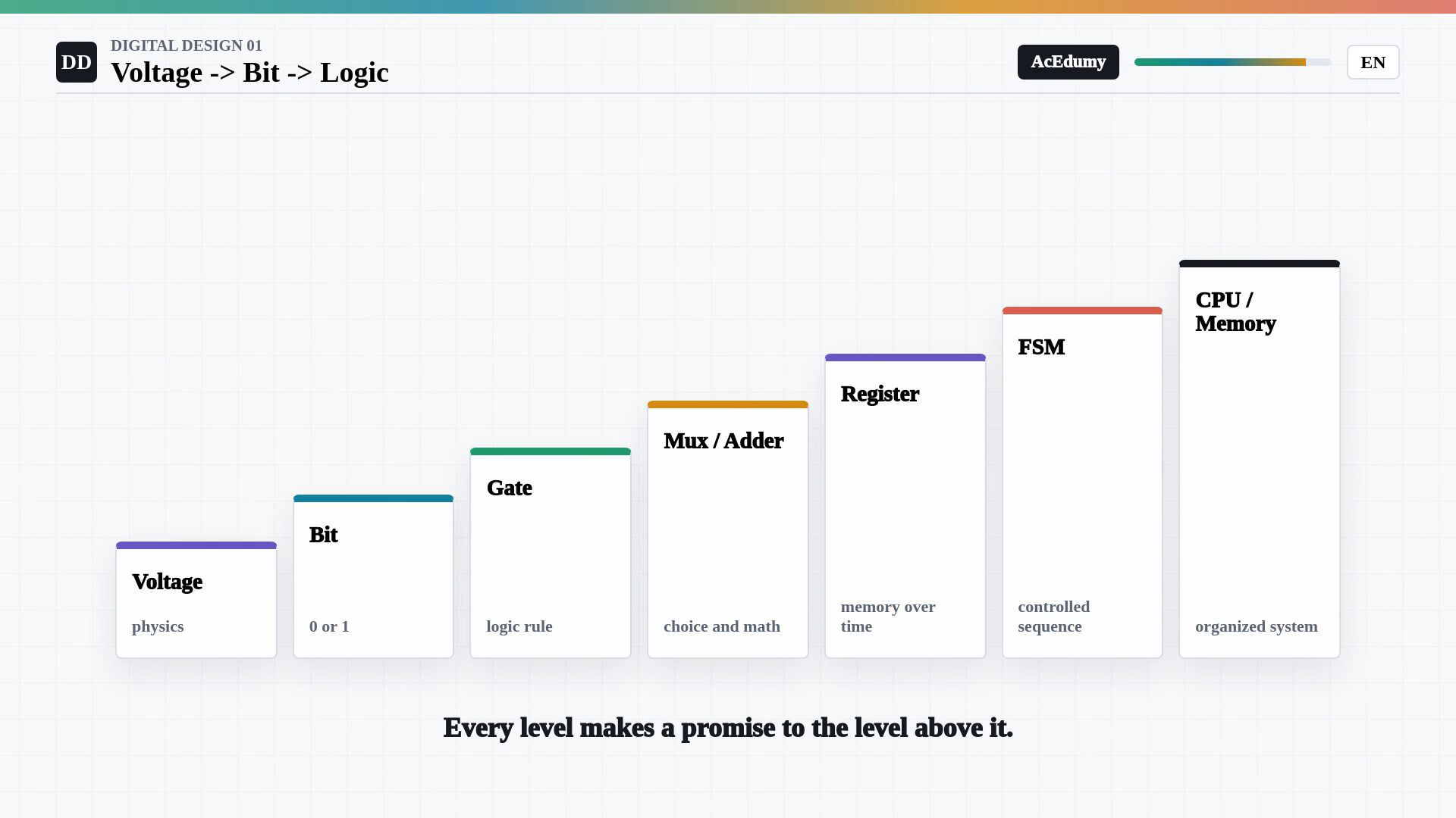
The example uses a three point three volt supply, a maximum guaranteed LOW input of zero point eight volts and a minimum guaranteed HIGH input of two volts. The displayed margins are distances from the given measured inputs to these limits. Equality belongs to the guaranteed ranges. Build larger systems from successive abstractions.Physical circuits carry real voltages.Specified input limits let valid voltages represent bits.Gates combine bits according to logic rules.Multiplexers select data, and adders perform binary arithmetic.Registers store bits over time.Finite-state machines combine stored state with logic to control sequences.Organized logic and storage form processors and memory systems.Each abstraction depends on the electrical and timing conditions of its underlying components.Narration transcript
This is why digital design scales. At the bottom, physics gives us voltages. Thresholds turn voltages into bits. Gates turn bits into logic. Multiplexers and adders turn gates into useful choices and arithmetic. Registers remember bits over time. Finite-state machines control sequences of decisions. And when these pieces are organized carefully, we can build processors and memory systems. Every level is a promise to the level above it.
7. Review the safe input ranges
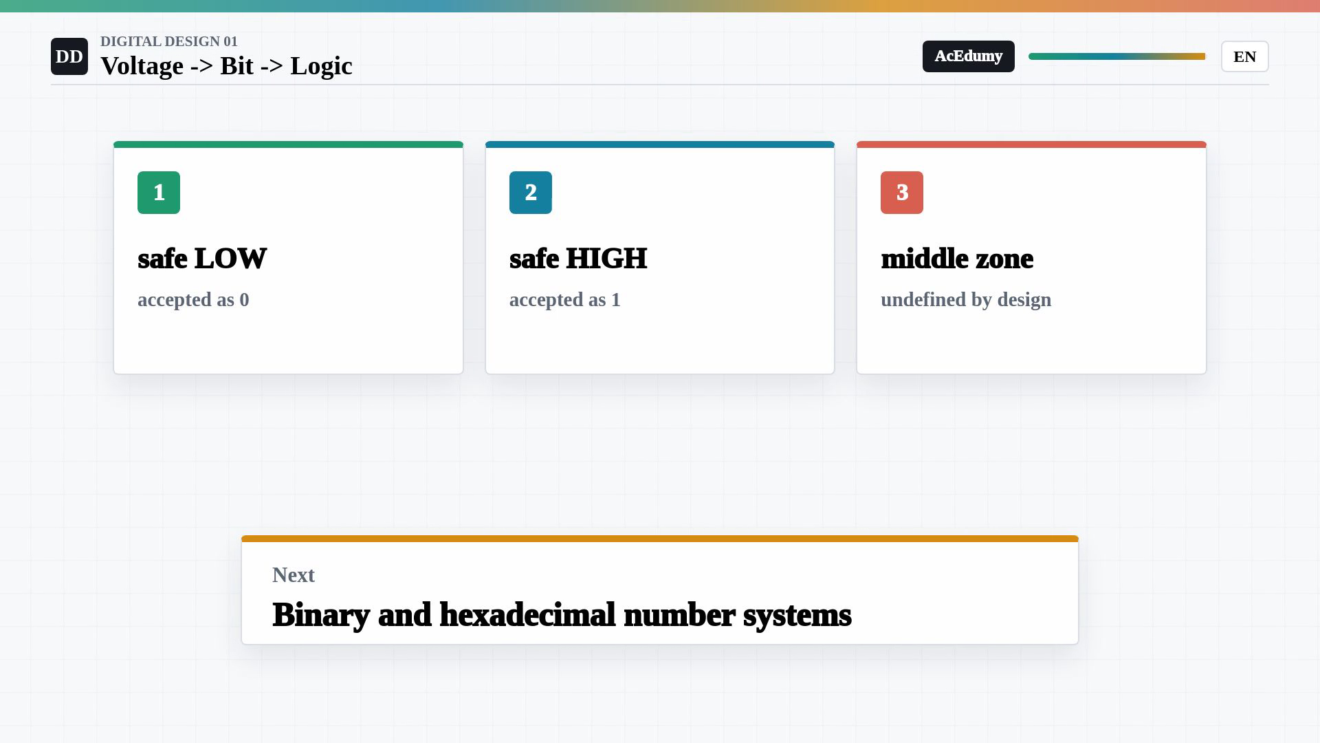
The example uses a three point three volt supply, a maximum guaranteed LOW input of zero point eight volts and a minimum guaranteed HIGH input of two volts. The displayed margins are distances from the given measured inputs to these limits. Equality belongs to the guaranteed ranges. Review voltage-to-bit abstraction.Digital logic retains an analog physical implementation.The abstraction provides a disciplined interface over physical voltages.Use the guaranteed LOW and HIGH ranges; do not rely on the undefined middle as a valid sampled bit.The next lesson introduces binary and hexadecimal representations of bit patterns.Narration transcript
So the first mental model is simple and powerful. Digital does not mean the analog world disappeared. It means we built a disciplined interface on top of it. Use safe low ranges for zero, safe high ranges for one, and avoid the undefined middle. Next we will learn the number systems that make those bits useful: binary, hexadecimal, and how to read bit patterns without getting lost.
Source video: Digital Design #01 | Voltage to Bit to Logic (4:06)