Electronics 1 · Electronics Basics
#02 Diode circuit analysis — forward bias, reverse bias, and series diodes
Choose the diode state, build its equivalent circuit, and solve two core examples with KVL and Ohm's law.
Question
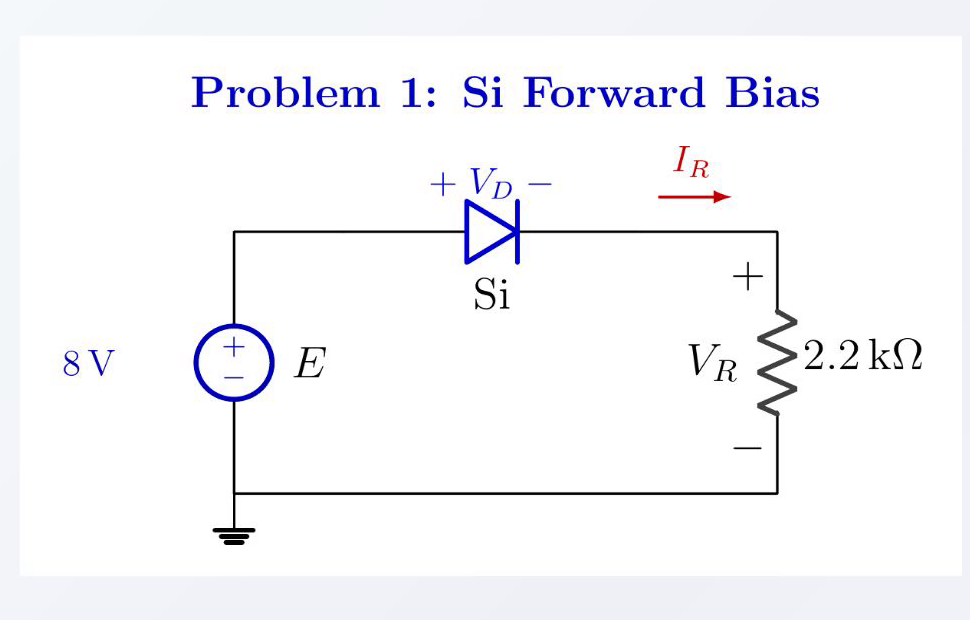
Use the constant-voltage diode model to solve two circuits. In the first, an 8 V source, a silicon diode, and a 2.2 kΩ resistor are in series; find I_R, V_R, and V_D for both source polarities. In the second, a 12 V source drives a forward-biased silicon diode, a forward-biased germanium diode, and a 5.6 kΩ resistor in series; find V_O and I_R. Use the signed reference V_D = V_A − V_K.
Written solution and narration transcript(shows the full solution)
Below are all the lines written in the notebook together with the full narration transcript.
1. Models and workflow
Three diode modelsSi ON:Ge ON:Ideal ON:State → equivalent → KVL → OhmNarration transcript
Welcome back. In the previous lesson, we built the three diode models: silicon at zero point seven volts, germanium at zero point three volts, and the ideal zero volt model. Today we put them to work. We will solve three classic textbook problems step by step. Same diode, same resistor, same source, but the answers change dramatically depending on which way the diode is pointing. By the end, you will know exactly how to find V_D, V_R, and I_R for any single-loop diode circuit. Let us start with the simplest case: a silicon diode in forward bias.
2. Example 1 — forward bias
The source makes the anode more positive than the cathode, so the silicon diode is ON. E = 8 V, R = 2.2 kΩ, Si diodeForward bias → diode ONIR = 7.3 / 2.2k = 3.32 mACheck: IR > 0, so ON is validNarration transcript
Here is the first circuit. A silicon diode in series with a two point two kilohm resistor, driven by an eight volt source. The diode is pointing in the same direction as the current would naturally flow, so this is forward bias. Three things we want to find: V_D, the voltage across the diode. V_R, the voltage across the resistor. And I_R, the current through the loop. Step one: is the diode on? We have eight volts pushing current forward, and the silicon turn-on voltage is only zero point seven. So yes, the diode is on. When silicon is on, we replace it with a zero point seven volt drop. That is our first answer: V_D equals zero point seven volts. Step two: apply Kirchhoff's voltage law around the loop. Eight volts equals V_D plus V_R. So V_R equals eight minus zero point seven, which is seven point three volts. Step three: Ohm's law on the resistor. I_R equals V_R divided by R, which is seven point three volts divided by two point two kilohms. That gives us three point three two milliamps. Three answers, three lines of work. And here is the formula you will use over and over: I equals E minus zero point seven, all divided by R.
3. Example 1 — reverse bias
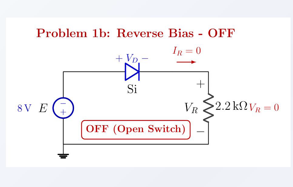
The circuit diagram is retained from the source lesson; the signed result is V_D = −8 V, while the reverse-voltage magnitude is 8 V. Same loop, source reversedReverse bias → diode OFFIR = 0 A and VR = 0 VReference:Narration transcript
Now I am going to flip the source. Same diode, same resistor, but the eight volt source is connected the other way around. The diode now sees a negative voltage at its anode. This is reverse bias. Will the diode conduct? No. Reverse-biased silicon stays off. It acts like an open switch. Open switch means no current can flow. I_R equals zero amperes. If there is no current, V_R is zero volts by Ohm's law. Now keep the voltage reference explicit: V_D equals V_A minus V_K. With the source's lower terminal as zero, the cathode is at zero volts because the resistor has no voltage drop, while the anode is at minus eight volts. Therefore signed V_D equals minus eight volts. The magnitude of the reverse voltage across the diode is eight volts. Polarity matters: flipping the source changes the diode from on to off, and the resistor current from three point three two milliamps to zero.
4. Example 2 — two diodes
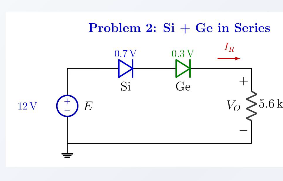
Both diodes are ON: use 0.7 V for silicon and 0.3 V for germanium. Si ON → VF,Si = 0.7 VGe ON → VF,Ge = 0.3 VFind VO and IRNarration transcript
Now for something more interesting. Two diodes in series, both forward biased. On the left, a silicon diode with zero point seven volts. On the right, a germanium diode with zero point three volts. Powered by a twelve volt source through a five point six kilohm resistor. Find V_O across the resistor, and the current I_R through the loop. The trick here is recognizing that since both diodes are on, we can simply replace each one with its forward voltage drop. And then it becomes plain old algebra.
5. Series solution
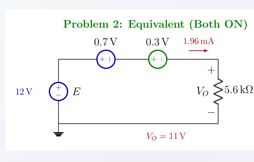
After the combined 1.0 V diode drop, 11 V remains across the resistor. KVL:IR = 1.96 mAGeneral:Narration transcript
Apply KVL around the loop. Twelve volts must equal the silicon drop plus the germanium drop plus V_O. Twelve equals zero point seven, plus zero point three, plus V_O. Combine the diode drops: zero point seven plus zero point three is one volt. Solve for V_O: twelve minus one equals eleven volts. V_O equals eleven volts. That is our first answer. Now for the current. Ohm's law on the resistor: I_R equals V_O divided by R, which is eleven volts over five point six kilohms. That gives us one point nine six milliamps. Notice something elegant here. When you have multiple diodes in series, all forward biased, you just add up their voltage drops and treat the whole stack as a single combined drop. Two diodes? Add them. Three diodes? Add all three. The principle is the same. Four LEDs in series at two volts each? That is eight volts you need to overcome before any current flows. Same algebra.
6. Summary and checks
Forward diode: ON → fixed VFReverse diode: OFF → I = 0KVL around the loopOhm's law on the resistorThree steps, same workflowNext: half-wave rectificationNarration transcript
Let us recap the workflow for any single-loop diode problem. First, look at each diode and decide: forward bias or reverse bias? Forward biased silicon means a zero point seven volt drop. Forward biased germanium means a zero point three volt drop. Reverse biased means no current at all. Second, apply Kirchhoff's voltage law around the loop. Source voltage equals the sum of all the drops. Third, use Ohm's law on the resistor to find the current. Three steps. Always the same three steps. Now you have a procedure that works on every single-loop diode problem you will see. In the next lesson, we put this to use on rectifier circuits, where the diode flips between on and off many times per second to convert AC into DC. See you there.
Source video: Electronics Basics #02 | Diode Worked Examples: Forward/Reverse + Si+Ge Series (6:13)