Electronics 1 · Electronics Basics
#01 Diode models — ideal, silicon, germanium, and the I–V curve
Identify diode polarity and compare the ideal, silicon, and germanium models without confusing a model with the physical device.
Question
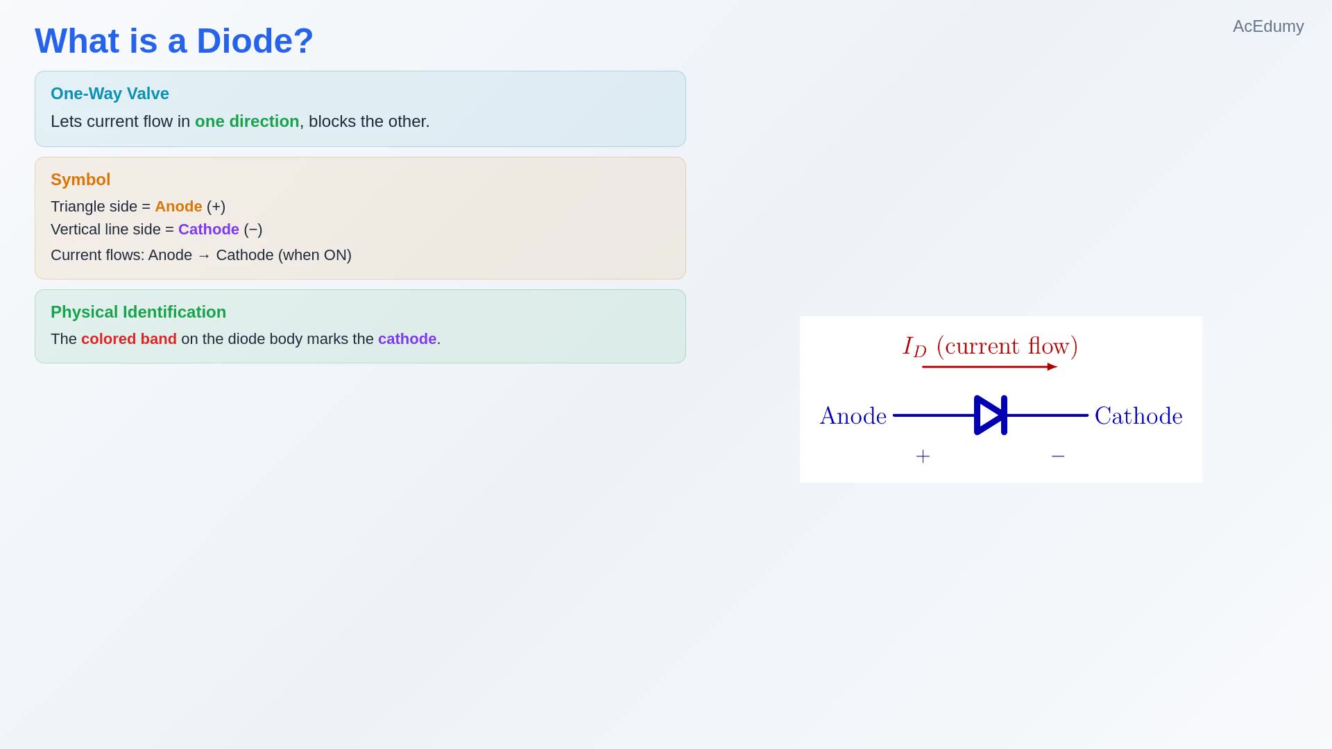
Explain the anode and cathode of a diode, then compare the ideal, silicon, and germanium analysis models and relate them to the diode I–V characteristic.
Written solution and narration transcript(shows the full solution)
Below are all the lines written in the notebook together with the full narration transcript.
1. What is a diode?
Diode: a two-terminal component that controls current by directionTerminals: anode (A) and cathode (K)Conventional forward current: anode → cathodeThe bar in the symbol and the band on the body mark the cathodeCommon introductory models: silicon, germanium, and idealNarration transcript
Hello everyone. Starting from this video, we are going to dive into electronics, and we will begin with the diode. Now, I want to keep this practical. We will not get lost in the internal semiconductor physics. Instead, we will learn just what you need to analyze circuits and solve problems. So, what is a diode? A diode is one of the most basic electronic components. It lets current flow in one direction, and blocks it in the other. Think of it like a one way valve for electricity. Here is the circuit symbol. The triangle side is the anode, and the vertical line side is the cathode. Current flows from anode to cathode when the diode is on. Plus on the anode side, minus on the cathode side. Now, in the lab, a real diode looks like a small glass or plastic cylinder with a colored band on one end. That band marks the cathode. So remember: the band is the cathode. That is all you need to know to place it correctly on a breadboard. The important thing is: how the diode behaves depends on what material it is made from. The two most common types are silicon and germanium. Let us look at each one.
2. Silicon model
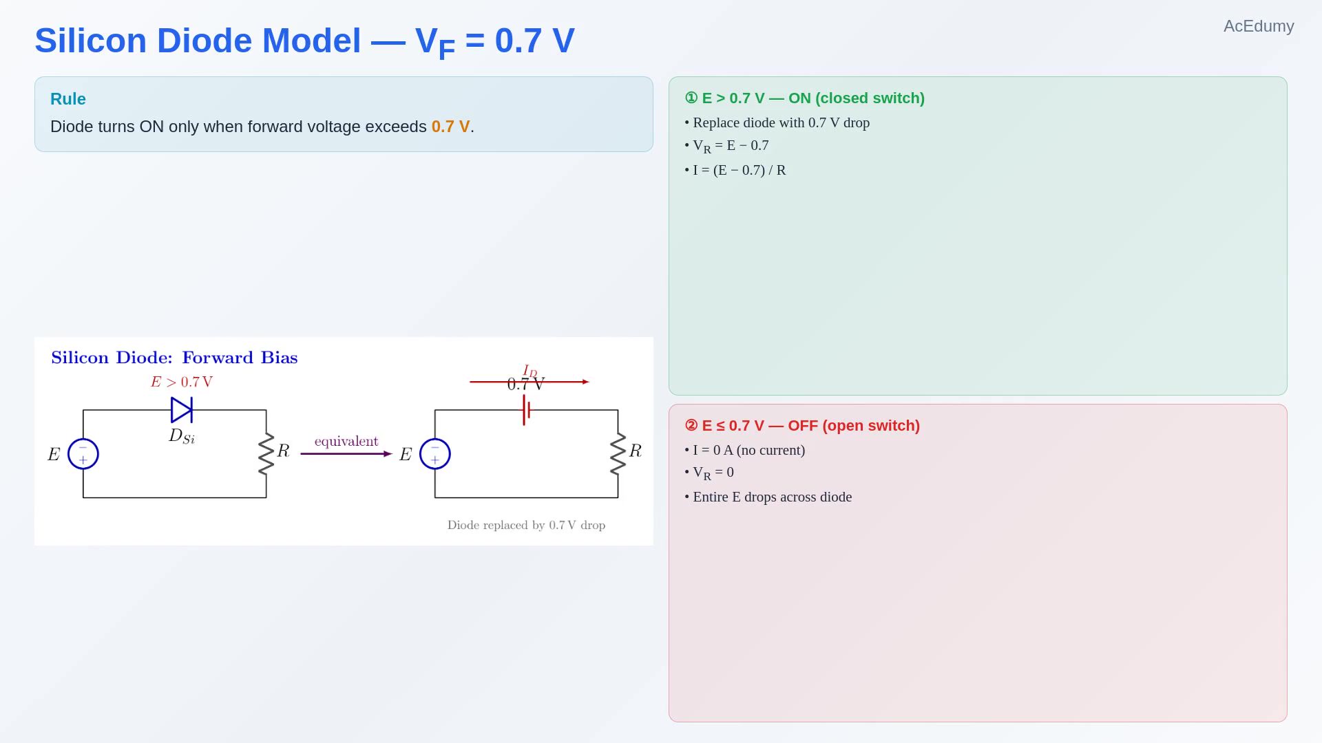 Constant-voltage silicon modelON approximation:OFF approximation: ID = 0 → open circuit0.7 V is a practical model value, not an exact universal threshold
Narration transcript
Let us start with the silicon diode, which is by far the most common. A silicon diode has a forward voltage of zero point seven volts. This is the toll it demands before it lets any current through. Imagine a simple circuit: a voltage source E, a silicon diode, and a resistor R. Now, there are exactly two scenarios. Scenario one: E is greater than zero point seven volts. The diode says, okay, you have paid the toll. I will let you pass. In this case, the diode turns on and acts like a short circuit with a zero point seven volt drop across it. So in the equivalent circuit, you simply replace the diode with a tiny zero point seven volt battery. The rest of the voltage, E minus zero point seven, drops across the resistor. Scenario two: E is less than zero point seven volts. The diode says, sorry, you have not reached my threshold. No entry. The diode stays off, and it acts like an open circuit. No current flows at all. Zero amps. The entire voltage E appears across the diode, and the resistor gets nothing.
3. Germanium model
Constant-voltage germanium modelON approximation:OFF approximation: ID = 0 → open circuitLower forward drop than siliconSilicon is more common in modern general-purpose circuitsNarration transcript
Germanium diodes work on the exact same principle, but with a lower threshold. Instead of zero point seven volts, the germanium diode needs only zero point three volts to turn on. So if E is greater than zero point three volts, the germanium diode conducts. You replace it with a zero point three volt drop, and the remaining voltage goes to the resistor. If E is less than zero point three volts, the diode stays off. Open circuit. No current. Compared to silicon, germanium turns on sooner because the barrier is lower. However, in modern electronics, silicon diodes are far more common. They have better thermal stability and are cheaper to manufacture. You will mostly see germanium diodes in older circuits or special applications like guitar pedals.
4. Ideal model
Ideal diode: a two-state switch modelON: VD = 0 and ID ≥ 0 → closed switchOFF: ID = 0 and VD ≤ 0 → open switchThe source and external circuit determine the currentUse the ideal model first, then add a forward-drop model when neededNarration transcript
Now, there is a third model: the ideal diode. This is a theoretical model used to simplify analysis. In the ideal model, there is no forward voltage drop at all. The threshold is zero volts. If any positive voltage is applied, even the smallest amount, the ideal diode conducts perfectly. Zero resistance, zero voltage drop. It behaves exactly like a closed switch. If the voltage is zero or negative, it behaves like an open switch. No current can pass. I like to think of it as a funnel. Current can enter from the wide end and come out the narrow end, no problem. But try to push it in from the narrow end? It does not fit. Now, why would we use such a simplified model? Because when you are first analyzing a circuit, you want to understand the overall behavior without getting distracted by small voltage drops. Start with the ideal model, build your intuition, and then add the zero point seven or zero point three later for accuracy.
5. I–V characteristic
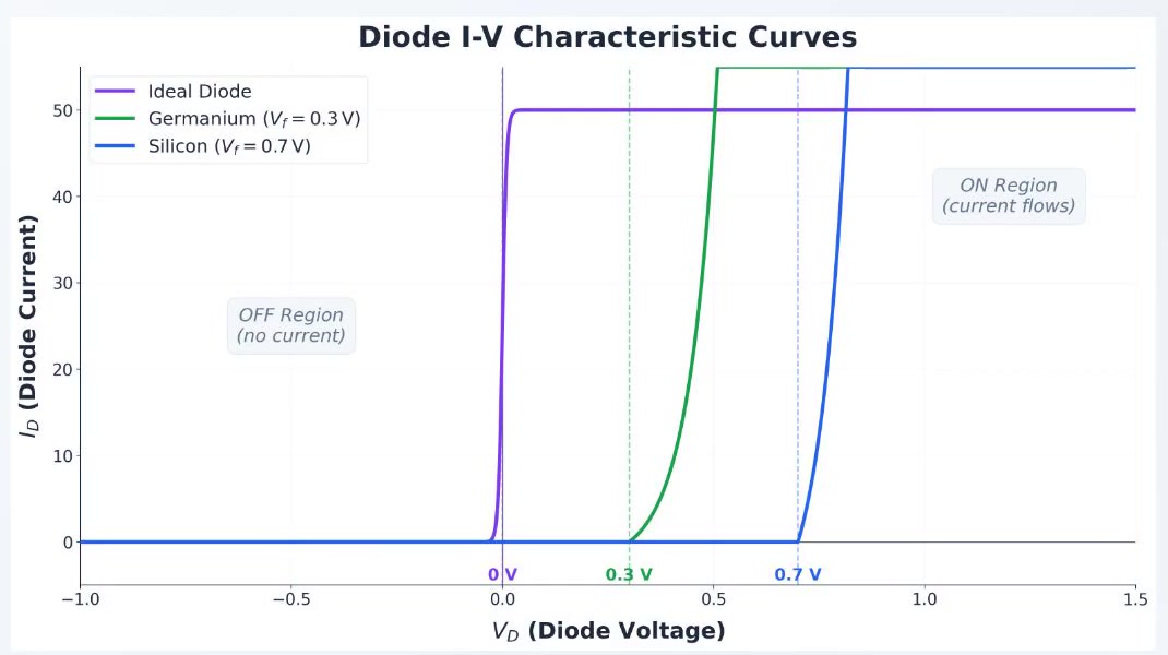 Horizontal axis: VD; vertical axis: IDIdeal model: VD = 0 in the ON stateGermanium approximation: knee near 0.3 VSilicon approximation: knee near 0.7 VA vertical ideal-model line does not mean the diode creates unlimited currentThe external circuit sets ID
Narration transcript
Now let us bring all three models together on a single graph. This is the I V characteristic curve. The horizontal axis shows the voltage across the diode, V D. The vertical axis shows the current through it, I D. Let us start with the ideal diode, shown in purple. For any negative voltage, the current is zero: a flat line along the axis. In the on state, the ideal model holds the diode voltage at zero while allowing forward current. The vertical line at zero volts does not mean that the diode creates unlimited current. The voltage source, resistors, and the rest of the external circuit determine the actual current. Next, the germanium diode is shown in green. In the constant-voltage approximation it begins conducting near zero point three volts. Finally, the silicon diode is shown in blue. The same approximate transition occurs near zero point seven volts. Notice the pattern: all three models separate an off region from an on region. The useful difference for introductory circuit analysis is the forward-voltage value assigned to each model.
6. Summary
Current reference: anode → cathodeSilicon model: VD ≈ 0.7 V when ONGermanium model: VD ≈ 0.3 V when ONIdeal model: VD = 0 when ONAlways state the model before solving the circuitNarration transcript
Let us recap what we covered. A diode is a one directional current device. Current flows from anode to cathode. The silicon diode model has a zero point seven volt forward threshold. Below that, it is off. Above that, it conducts with a zero point seven volt drop. The germanium diode model has a zero point three volt threshold. Same logic, lower barrier. The ideal diode model has zero forward voltage. It is a perfect switch: on when forward biased, off when reverse biased. The I V characteristic curve shows all of this visually. In the next lesson, we will put these models to work by solving actual diode circuit problems step by step. See you there.
Source video: Electronics Basics #01 | Introduction to Diodes: Si/Ge/Ideal + I-V Curve (7:09)