Electronics 1 · Electronics Basics
#09 Double-source clipper — two-level limiting
Use two opposite shunt branches to limit both sides of a waveform and derive the ideal and 0.7 V silicon windows.
Question
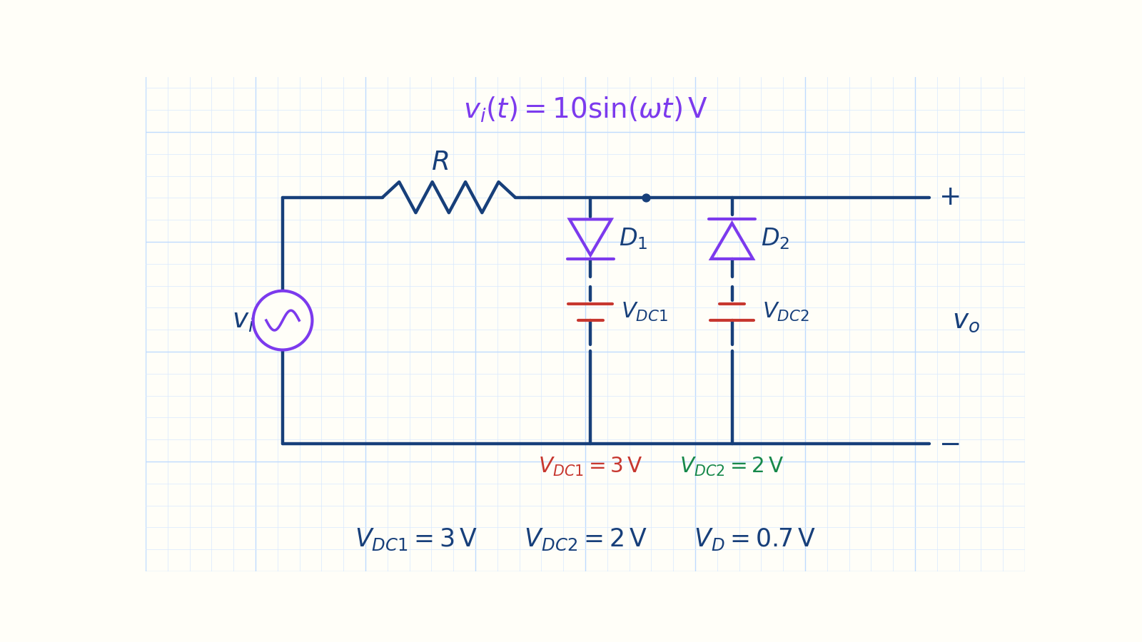
Analyze the double-source clipper for v_i(t) = 10 sin(ωt) V, V_DC1 = 3 V, and V_DC2 = 2 V. With ideal diodes, determine the ON/OFF regions of D1 and D2, the piecewise output rule v_o(t), and the output window. Then find both transition levels for a constant-drop silicon model with V_D = 0.7 V.
Written solution and narration transcript(shows the full solution)
Below are all the lines written in the notebook together with the full narration transcript.
1. Why two limits?
D1 sets the upper limit and D2 sets the lower limit; both branches share the output and reference rails. One diode branch → one clipping levelEither the positive or negative peak is limitedTwo opposite shunt branches → two thresholdsD1 sets the upper limit; D2 sets the lower limitThe output is trapped inside a voltage windowNarration transcript
Welcome back. Over the last four lessons we built twelve clipper variations. Each one used a single diode and at most one DC source. That means each circuit could only clip at one level. Either the positive peak was cut, or the negative peak was cut, but never both at the same time. Today we ask: what if we want to limit the output on both sides? The answer is simple. We place two shunt branches in parallel with the output. Each branch has its own diode and its own DC source. One branch clips the positive peak, the other clips the negative peak. This is the double-source clipper, also called a two-level limiter.
2. Read the circuit
D1 sets the upper limit and D2 sets the lower limit; both branches share the output and reference rails. vi → R → output node voD1 + VDC1 → upper-limit branchD2 + VDC2 → lower-limit branchBoth branches share the same vo nodeBetween thresholds: D1,D2 OFF → vo = viNarration transcript
Here is the circuit. The input sine wave goes through a series resistor R to the output node. At that node, two branches connect down to ground. The first branch has diode D one in series with battery V DC one. D one is oriented so that it conducts when the input is sufficiently positive. The second branch has diode D two in series with battery V DC two. D two is oriented in the opposite direction, so it conducts when the input goes sufficiently negative. Each branch works independently. When the input is in the middle range, both diodes are off, and the output simply follows the input.
3. Three ideal regions
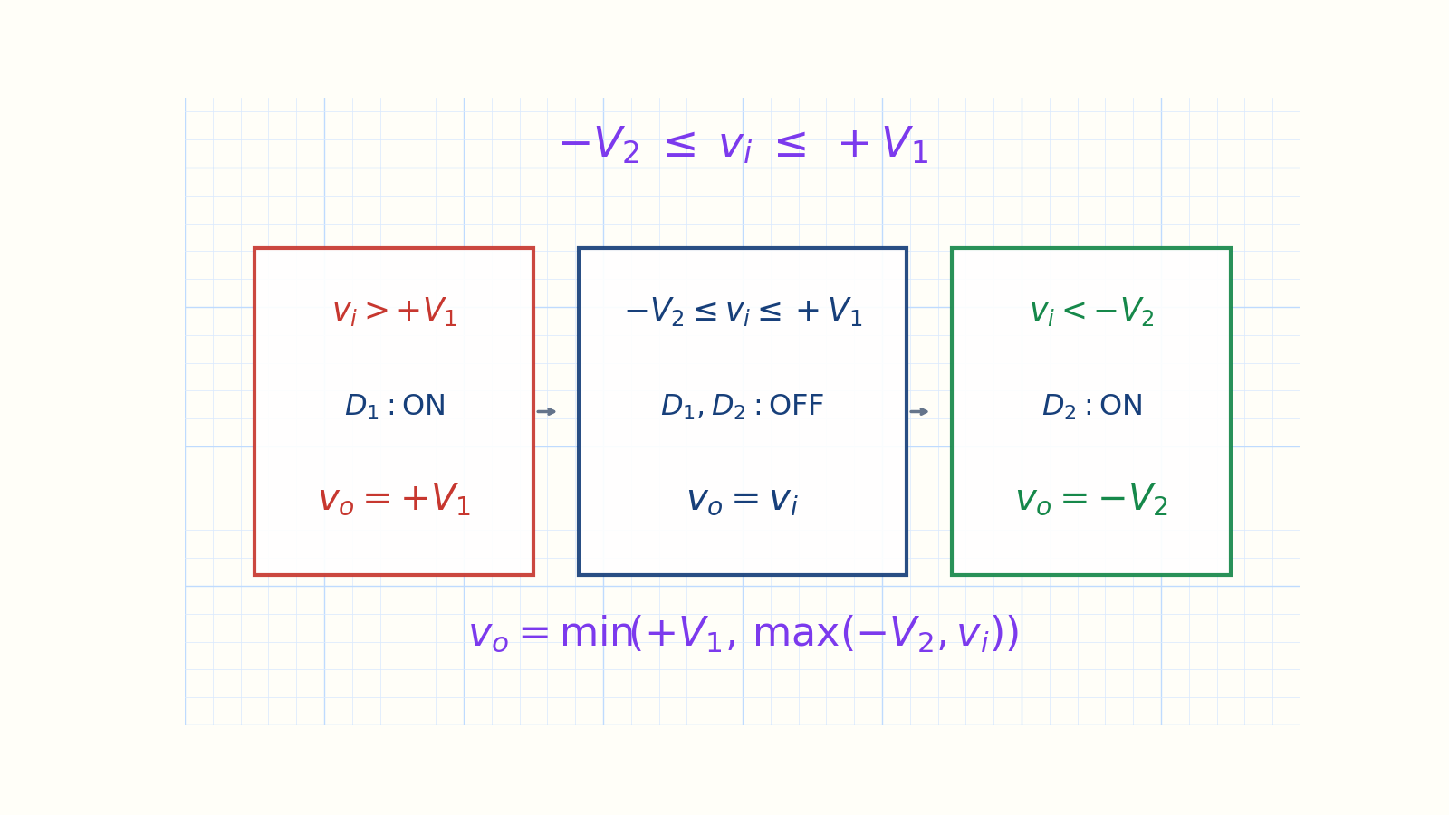
The output follows the input in the middle and locks to a limit outside the window. At transition: iD = 0 and vD = 0vi > +V1 → D1 ON → vo = +V1−V2 ≤ vi ≤ +V1 → both OFF → vo = vivi < −V2 → D2 ON → vo = −V2vo = min(+V1, max(−V2, vi))Narration transcript
Let us find the two transition voltages. For the upper branch, set the current to zero and the diode voltage to zero. Kirchhoff's voltage law around the upper shunt branch gives the transition voltage V T one equals plus V one. When the input exceeds plus V one, D one turns on and the output locks at plus V one. For the lower branch, the same method gives the transition voltage V T two equals minus V two. When the input drops below minus V two, D two turns on and the output locks at minus V two. Between these two levels, both diodes are off, and the output equals the input. So the circuit creates three distinct regions. Region one: input above plus V one, output locked at plus V one. Region two: input between the two transitions, output follows input. Region three: input below minus V two, output locked at minus V two.
4. Ideal waveform
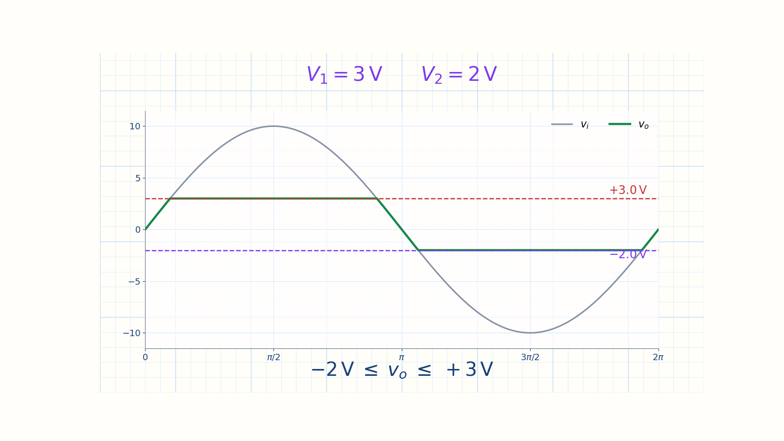
The ideal output window extends from minus 2 volts to plus 3 volts. The positive crest flattens at +3 VThe negative trough flattens at −2 VThe output follows the sine in betweenIdeal window:Narration transcript
Here is what the output looks like with an ideal diode. The input is a ten-volt peak sine wave. Every time the sine rises above plus V one, the output flattens out at plus V one. Every time the sine dips below minus V two, the output flattens at minus V two. In between, the output traces the original sine shape. The result is a sine wave with both peaks clipped off. The output is trapped inside a voltage window from minus V two to plus V one. If V one does not equal V two, the window is asymmetric.
5. Silicon window
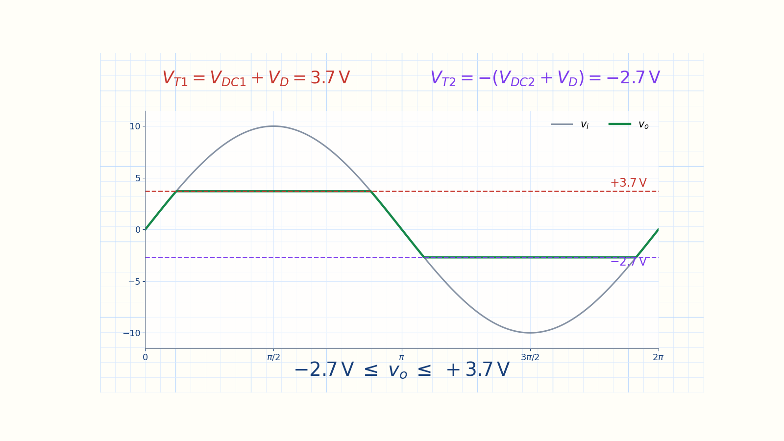
The 0.7-volt diode drops move both limits away from zero. Constant-drop model:Both limits move away from zeroSi window:Narration transcript
Now let us add the silicon diode drop. In this example, V DC one is three volts, V DC two is two volts, and each silicon diode has a forward voltage V d of 0.7 volts. The upper transition becomes V DC one plus V d, that is three plus 0.7, which equals 3.7 volts. The lower transition becomes minus the quantity V DC two plus V d, that is minus the quantity two plus 0.7, which equals minus 2.7 volts. So the output window is from minus 2.7 volts to plus 3.7 volts. Notice this is asymmetric. The positive clipping level is 3.7 volts above zero, but the negative clipping level is only 2.7 volts below zero. If you wanted a symmetric window, you would set V DC one equal to V DC two.
6. Method summary
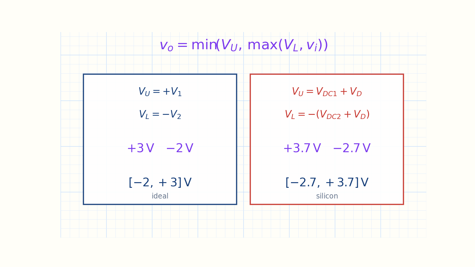
The general min-max rule and both output windows are shown together. General: vo = min(VU, max(VL, vi))Ideal:Si:Si:Find transitions → test regions → sketch the waveformNext: clamper circuitsNarration transcript
And with that, the clipper series is complete. We covered thirteen variations across five lessons. Series simple clippers, with the diode in series. Series biased clippers, adding a DC source in series. Parallel simple clippers, with the diode in the shunt branch. Parallel biased clippers, adding a DC source to the shunt branch. And finally, the double-source clipper, combining two branches for two-level limiting. The key method was always the same: set the current to zero, set the diode voltage to zero, and find the transition voltage. Next topic: clamper circuits. Instead of cutting off peaks, a clamper shifts the entire waveform up or down without changing its shape.
Source video: Electronics Basics #09 — Double-Source Clipper (4:58)