Electronics 1 · Electronics Basics
#28 Gate–source short: zero bias does not mean zero drain current
Question
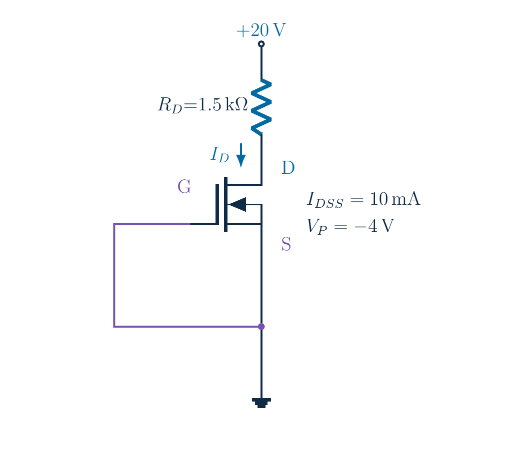
A wire joins the gate and source of a depletion MOSFET. Does that turn it off or short the channel? Find V_DS for V_DD=20 V, R_D=1.5 kΩ, I_DSS=10 mA and V_P=−4 V, and verify the operating region.
Written solution and narration transcript(shows the full solution)
Below are all the lines written in the notebook together with the full narration transcript.
1. The goal: distinguish a gate short from a channel short
Gate–source wire: off state or channel short? Neither followsWire fixes VGS, not VDS; find channel voltage and check modelNarration transcript
Start with the complete circuit. The gate is connected directly to the source, and that node is grounded. Does this wire turn the transistor off, or does it short out the channel? Neither conclusion follows automatically. The wire sets the voltage between gate and source. It does not join drain to source. Our task is to find the voltage across this particular depletion MOSFET and check that the current model we use is valid.
2. The goal: distinguish a gate short from a channel short
Depletion MOSFET; no RS or RG; gate and source directly joinedNarration transcript
Read the original values and connections. The supply is twenty volts, and the drain resistor is one point five kilohms. I D S S is ten milliamps, and V P is negative four volts. The symbol is an n-channel depletion MOSFET, with a solid channel and body tied to source. There is no source resistor and no gate resistor in this example. Do not carry either resistor over from the previous self-bias circuit. Here a direct wire joins gate and source.
3. The wire fixes the control voltage, not the drain current
Connection gives equality; grounding is not needed for VGS=0Narration transcript
An ideal wire puts both ends at the same potential. Therefore gate voltage equals source voltage. Subtracting the source voltage from the gate voltage gives zero volts. We know V G S directly from the connection, so no quadratic equation is needed to discover it. Grounding the shared node also makes both node voltages zero relative to ground. The important fact is their equality: even without choosing ground there, an ideal gate-source short would still impose zero voltage between those two terminals.
4. At zero bias, a depletion channel is already present
Saturation factor:Candidate ID=IDSS=10 [mA]Still prove sufficient VDS for saturationNarration transcript
Substitute zero gate-source voltage into the ideal square-law saturation equation. Zero divided by negative four is zero. One minus zero is one, and the squared factor is one. The predicted drain current is therefore I D S S, or ten milliamps. This is what the zero-bias current parameter means in this model. But we have not yet proved that the drain has enough voltage for saturation. Treat this current as a candidate until the circuit-voltage calculation confirms the assumption.
5. At zero bias, a depletion channel is already present
Normally on at VGS=0; cutoff at −4 V, not zeroNegligible gate leakage ≠ zero drain current; not enhancement-onlyNarration transcript
Why is the current not zero? A depletion MOSFET already has a conducting channel at zero control voltage. A sufficiently negative gate-source voltage is needed to deplete it to cutoff; the supplied boundary is negative four volts, not zero. Also distinguish gate current from drain current. The gate insulation makes steady gate leakage negligible in the ideal model, but it does not remove the drain-source conduction path. Do not apply the normally-off intuition of an enhancement MOSFET to this depletion device.
6. Find the resistor drop, then the transistor voltage
0.01 A × 1500 Ω gives the same result15 V is across the resistor, not transistorNarration transcript
Now use the candidate current in the drain resistor. Ohm's law gives the voltage drop as current times resistance. Ten milliamps times one point five kilohms equals fifteen volts. The units work because the milli and kilo factors cancel. Equivalently, zero point zero one amp times one thousand five hundred ohms gives the same drop. This fifteen-volt result is across the resistor, not across the transistor. The supply voltage has to be shared between both elements in the drain-source loop.
7. Find the resistor drop, then the transistor voltage
Here VD=VDS because VS=0; do not generalizeNarration transcript
Apply Kirchhoff's voltage law around the loop. The twenty-volt supply equals the fifteen-volt resistor drop plus the drain-source voltage. Subtracting the drop leaves five volts across the transistor. Since the source is directly grounded in this particular circuit, the drain-to-ground voltage is also five volts. That equality would not generally hold with a source resistor lifting the source potential. Keep the references explicit even when the arithmetic is short: V D S always means drain voltage minus source voltage.
8. Check the saturation assumption explicitly
Boundary:5 V ≥ 4 V → accept ID=10 [mA], VDS=5 VGate domain passed; device voltage/power ratings assumed adequateNarration transcript
Do not stop at the five-volt answer. The square-law saturation assumption requires V D S to be at least V G S minus V P. With zero minus negative four, the required boundary is four volts. The circuit supplies five volts across the transistor, so the saturation check passes. We can now accept ten milliamps and five volts as the ideal operating point. The negative threshold also places zero gate-source voltage in the conducting domain. Suitable breakdown and power ratings remain an assumption about the real device.
9. Check the saturation assumption explicitly
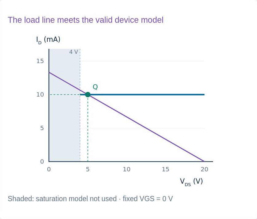
Original lesson graph; ideal DC model. Loop: 15 V + 5 V = 20 V; device and region agreeA gate–source short alone does not guarantee IDSS: supply and RD matterNarration transcript
The voltage loop closes: fifteen volts across the resistor plus five volts across the transistor equals twenty volts. The current agrees with the zero-bias device model, and the saturation check has passed. The important limitation is that a gate-source short alone does not guarantee I D S S for every supply and drain resistance. If the circuit did not provide enough drain-source voltage, this saturation assumption would fail and a different operating-region model would be needed. We have checked it rather than assuming it.
10. A simple answer still needs a physical check
Load line:Saturation branch starts at 4 V; intersection at (5 V, 10 [mA])Below 4 V the flat saturation-current model is not usedNarration transcript
The graph compares the circuit and the device without changing the example. The purple load line represents current equal to supply minus transistor voltage, divided by drain resistance. The blue line shows the ideal ten-milliamp zero-bias current only in saturation, starting at the four-volt boundary. Their intersection is at five volts and ten milliamps. The region below the boundary is shaded because the flat saturation-current model is not used there. This picture shows why checking the available transistor voltage matters.
11. A simple answer still needs a physical check
Connection → correct device → candidate current → voltage → regionAnswer: VGS=0, ID=10 [mA], VDS=5 V; gate short is not channel shortNarration transcript
The complete method is short but disciplined. Read the gate-source connection to determine the control voltage. Use the correct depletion-device model to obtain a candidate current. Calculate the drain-resistor drop, subtract it from the supply, and verify saturation. Do not confuse negligible gate current with zero drain current, and do not confuse a gate-source short with a drain-source short. In the supplied circuit, all the ideal checks agree: zero gate-source voltage, ten milliamps of drain current, and five volts across the transistor.
Source video: Electronics Basics #28 | Gate-Source Short: Depletion MOSFET DC Analysis (6:42)