Electronics 1 · Electronics Basics
#29 Enhancement MOSFET drain–gate feedback bias
Question
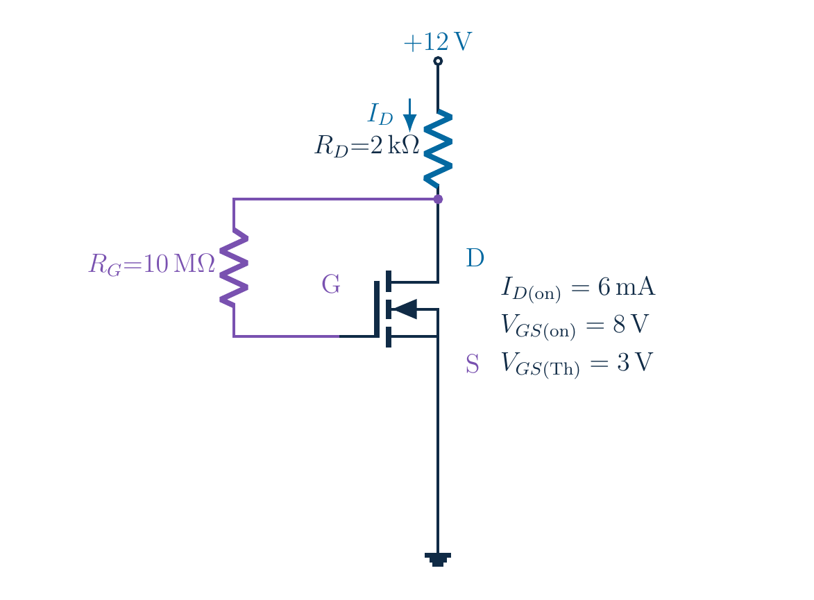
With a 10 MΩ resistor from drain to gate, is the gate grounded? Find the DC operating point for V_DD=12 V and R_D=2 kΩ. The MOSFET carries 6 mA at V_GS=8 V and has V_T=3 V. Determine k, test both roots and verify saturation.
Written solution and narration transcript(shows the full solution)
Below are all the lines written in the notebook together with the full narration transcript.
1. The goal: find the current and the gate voltage
Drain feeds insulated gate through a resistor; source groundedFind ID and VGS; feedback returns drain voltage to gateNarration transcript
Start with the full circuit and follow the feedback wire. A resistor joins the drain to the insulated gate, while the source is grounded. The gate is not connected directly to the supply, and it is not tied to ground. As drain current changes, the drain voltage changes, and this connection brings that voltage back to the gate. Our goal is to find the steady drain current and gate-source voltage, then test whether the assumed transistor model is consistent.
2. The goal: find the current and the gate voltage
ID(on)=6 [mA] at VGS(on)=8 V; VT=3 VEnhancement MOSFET: normally off at zero gate biasNarration transcript
Keep the original values. The supply is twelve volts, the drain resistor is two kilohms, and the feedback resistor is ten megohms. The device carries six milliamps at a gate-source voltage of eight volts. Its threshold voltage is three volts. We will call that threshold V T for shorter equations. The broken channel identifies an enhancement MOSFET. Unlike the depletion devices in the previous examples, this ideal device is off when gate-source voltage is zero.
3. Build the enhancement-device equation
Require VGS>VT and VDS≥VGS−VTNegative overdrive squared is not physical conduction; ideal modelNarration transcript
For a conducting enhancement MOSFET in saturation, drain current equals k times the square of gate-source voltage minus threshold voltage. Two conditions belong with that formula. Gate-source voltage must exceed threshold, and drain-source voltage must be at least the overdrive voltage. Squaring a negative overdrive does not turn an off transistor into a conducting one. We will preserve those conditions when selecting a root. This ideal model also neglects channel-length modulation and assumes suitable device ratings.
4. Build the enhancement-device equation
Here k is the full square-law coefficient; do not add another 1/2Narration transcript
Use the supplied on-state point to determine k. Divide six milliamps by the square of eight minus three volts. The denominator is twenty-five volts squared, so k is zero point two four milliamps per volt squared. In amperes, that is two point four times ten to the minus four amperes per volt squared. Our definition already includes the full coefficient multiplying the square. Some books place a factor of one half in a different parameter convention; do not mix the two conventions.
5. The drain feeds back to the gate
IG≈0 → no DC drop across RF → VG=VDNot zero gate voltage; grounded source gives VGS=VDSEquality follows this drain-to-gate connectionNarration transcript
Now read the feedback resistor correctly. The insulated gate draws negligible steady current, so the current in the ten-megohm resistor is approximately zero. Its voltage drop is therefore approximately zero, which means gate voltage equals drain voltage. It does not mean that gate voltage is zero. The source is grounded, so gate-source voltage also equals drain-source voltage. This equality is the key simplification. It comes from the actual drain-to-gate connection and would not apply to a gate resistor connected to ground.
6. The drain feeds back to the gate
Narration transcript
The drain resistor carries approximately the drain current because gate current is negligible. Its drop is I D times two kilohms. Subtract that drop from twelve volts to get the drain voltage, and therefore the gate-source voltage. Let x be the numerical current in milliamps. Milliamps multiplied by kilohms give volts, so the circuit relation is twelve minus two x. Writing the units explicitly now prevents a thousand-fold error when we insert this relation into the device equation.
7. Combine the circuit and the device
Combine circuit voltage with enhancement square lawTwo algebraic candidates; conduction condition stays attachedNarration transcript
Combine the two descriptions of the same operating point. The device equation contains gate-source voltage, and the feedback circuit expresses that voltage in terms of current. Substitute twelve minus two x for gate-source voltage, then subtract the three-volt threshold. The result is zero point two four times the square of nine minus two x, equal to x. We have one unknown, but the square produces two algebraic candidates. The original conduction condition still applies and will decide which candidate is physical.
8. Combine the circuit and the device
x=19.44−8.64x+0.96x2; move xNarration transcript
Expand carefully. Nine minus two x, squared, gives eighty-one minus thirty-six x plus four x squared. Multiplying by zero point two four gives nineteen point four four minus eight point six four x plus zero point nine six x squared. Move the x on the left to the right. The linear coefficient becomes negative nine point six four. Our quadratic is zero point nine six x squared minus nine point six four x plus nineteen point four four, equal to zero. Keep the coefficients unrounded for the root calculation.
9. Two mathematical roots, one physical answer
Candidate ID≈2.794 [mA] or 7.248 [mA]Choose by terminal voltages, not root sizeNarration transcript
Apply the quadratic formula with a equal to zero point nine six, b equal to negative nine point six four, and c equal to nineteen point four four. The discriminant is eighteen point two eight. Divide nine point six four plus or minus the square root of that discriminant by one point nine two. The two candidate currents are approximately two point seven nine four and seven point two four eight milliamps. Do not choose a root simply because it is smaller. Test what each candidate implies for the transistor voltages.
10. Two mathematical roots, one physical answer
Large root → VGS≈−2.495 V < VT=3 VAlso ID≈7.248 [mA] > 12 V/(2 kΩ)=6 [mA]Reject: negative overdrive outside conducting modelNarration transcript
Test the larger candidate first. Substitute its full-precision current into twelve minus two x. Gate-source voltage becomes approximately negative two point four nine five volts, which is below the positive three-volt threshold. The conducting square-law model is therefore invalid for this root. There is a second warning: seven point two four eight milliamps exceeds the six milliamps that twelve volts could drive through the two-kilohm resistor even with zero transistor voltage. Reject this candidate; squaring a negative overdrive created a mathematical solution outside the model's domain.
11. Two mathematical roots, one physical answer
Accepted candidate:6.412 V > 3 V: conduction check passesNarration transcript
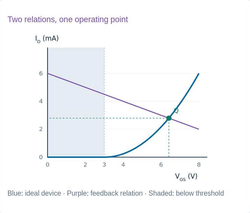
Now test the other candidate using full precision. The current is about two point seven nine four milliamps. The drain-resistor drop is about five point five eight eight volts, leaving six point four one two volts at the drain. Gate voltage follows the drain, and the grounded source makes this both gate-source and drain-source voltage. Six point four one two volts exceeds the three-volt threshold, so the conduction condition passes. The displayed values match the original example after rounding.
12. Check conduction, saturation and the supply
Overdrive:6.412 V ≥ 3.412 V: saturation passesVDS=VGS and VT>0 make saturation automatic only after conductionNarration transcript
Check saturation rather than stopping at the conduction test. The overdrive is gate-source voltage minus threshold, about three point four one two volts. Drain-source voltage is six point four one two volts, so the saturation condition passes. In fact, this connection gives an elegant general check. Because gate and drain share the same ideal DC voltage, V D S equals V G S. Subtracting a positive threshold from the right-hand side makes the inequality automatic for a conducting device. Conduction itself must still be verified separately.
13. Check conduction, saturation and the supply
Original lesson graph; ideal model. Loop:Device substitution returns ID≈2.794 [mA]Check original circuit and device, not polynomial aloneNarration transcript
Perform two independent numerical checks. First, the resistor drop and transistor voltage must add back to the supply: approximately five point five eight eight plus six point four one two equals twelve volts. Second, insert the unrounded gate-source voltage into the original device equation. Zero point two four times the square of that voltage minus three returns approximately two point seven nine four milliamps. These checks use both the circuit and the device. A root that only satisfies the expanded polynomial is not enough.
14. See the operating point and the feedback
Device curve above threshold meets descending feedback lineID rises → VD and VG fall → oppose rise; not a dynamic stability proofNarration transcript
The graph makes the feedback visible. The blue device curve rises only after gate-source voltage exceeds the three-volt threshold; below threshold the ideal current is zero. The purple circuit line falls because a larger current creates a larger drain-resistor drop and lowers the voltage sent back to the gate. Their intersection is the operating point we checked. If current tends to increase, the feedback tends to reduce gate voltage and oppose that increase. This explains the direction of negative feedback, not a claim of perfect stability or a complete dynamic analysis.
15. See the operating point and the feedback
Connections → k → VG=VDSolve; test conduction, supply, saturation and voltage loopRF still exists: leakage and gate capacitance matter in real hardwareNarration transcript
The complete workflow starts with the connection, not the quadratic formula. Determine k from the supplied device point. Use negligible gate current to relate gate voltage to drain voltage. Combine that circuit relation with the correct enhancement-device equation, solve the quadratic, and reject candidates that violate conduction or the supply. Then verify saturation and the voltage loop. The ten-megohm resistor has not disappeared physically: real leakage and gate capacitance matter. Our ideal steady-state example explains the operating point, not a universal resistor-selection rule.
Source video: Electronics Basics #29 | Enhancement MOSFET: Drain-to-Gate Feedback Bias (9:41)