Electronics 1 · Electronics Basics
#35 Two input current paths: transistor branch versus total input
Question

The signal source delivers more current than the transistor branch needs. Where does the extra current go? Distinguish total input resistance, transistor-branch resistance, stage gain and source gain, starting from a valid bias point.
Written solution and narration transcript(shows the full solution)
Below are all the lines written in the notebook together with the full narration transcript.
1. What does the signal source actually drive?
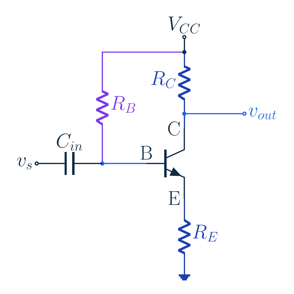
Original source visual. RT is a port equivalent, not an added physical resistor. Any animated panel loops forward independently of audio; current gauges share a scale. Why is source current larger than transistor-branch current?Bias resistor provides a second input path; distinguish stage/source gainNarration transcript
Your signal source is connected to an amplifier input. You know the resistance looking into the transistor, so you expect a certain input current. But the source supplies more current than that calculation predicts. Where does the extra current go? In this circuit the base bias resistor provides a second path. We will first trace those two paths, then find the resistance seen by the source and distinguish amplifier gain from the gain measured all the way from that source.
2. What does the signal source actually drive?
Collector output: common emitter, not follower; RE unbypassedSupply-to-base RB sets DC bias and also draws signal currentNarration transcript
The output is still taken from the collector, so this is a common emitter amplifier, not an emitter follower. The collector resistor connects to the positive supply. The external emitter resistor is not bypassed. The new element to track is the resistor from the supply to the base. It helps establish the direct current operating point, but it also draws signal current. A component can participate in both the bias circuit and the small signal circuit without playing the same role in each.
3. Separate the bias circuit from the signal model
Original source visual. RT is a port equivalent, not an added physical resistor. Any animated panel loops forward independently of audio; current gauges share a scale. DC: coupling capacitor isolates generator; solve bias circuitMidband AC: capacitor ≈ short; constant supply → signal groundNot a physical supply short; do not clamp DC base with AC generatorNarration transcript
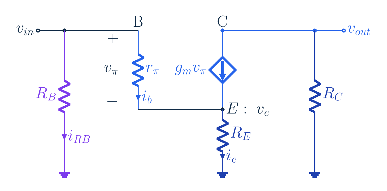
Separate the two analyses before touching an equation. For direct current, the signal generator is isolated by a coupling capacitor and we solve the bias network. For a midband small signal, the capacitor is approximately a short and the constant supply becomes signal ground. This means the upper end of the base resistor is at signal ground. It does not mean we physically short a supply, and it does not mean a zero mean ideal voltage source should clamp the transistor base to zero volts at direct current.
4. Separate the bias circuit from the signal model
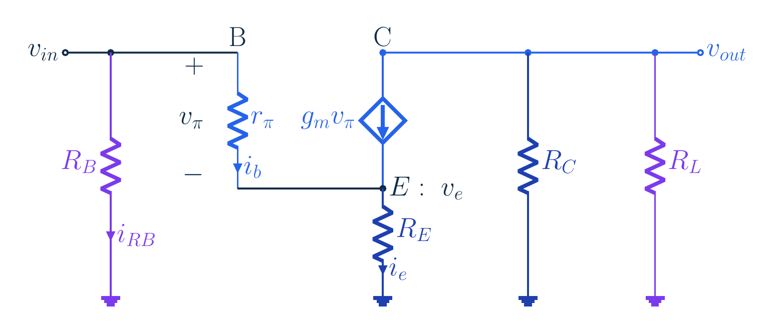
Hybrid-π:ro → ∞; no transistor capacitances; vin=vπ+veNarration transcript
Replace the transistor with the hybrid pi model. Base current flows through r pi into the emitter, while the controlled collector current is g m times v pi. Their sum passes through the emitter resistor. We neglect transistor capacitances and explicitly take output resistance r o as infinite. The emitter voltage can move because its resistor remains in the circuit. Therefore the input voltage at the base is the base emitter signal voltage plus the emitter signal voltage, not v pi alone.
5. Two paths, one input voltage
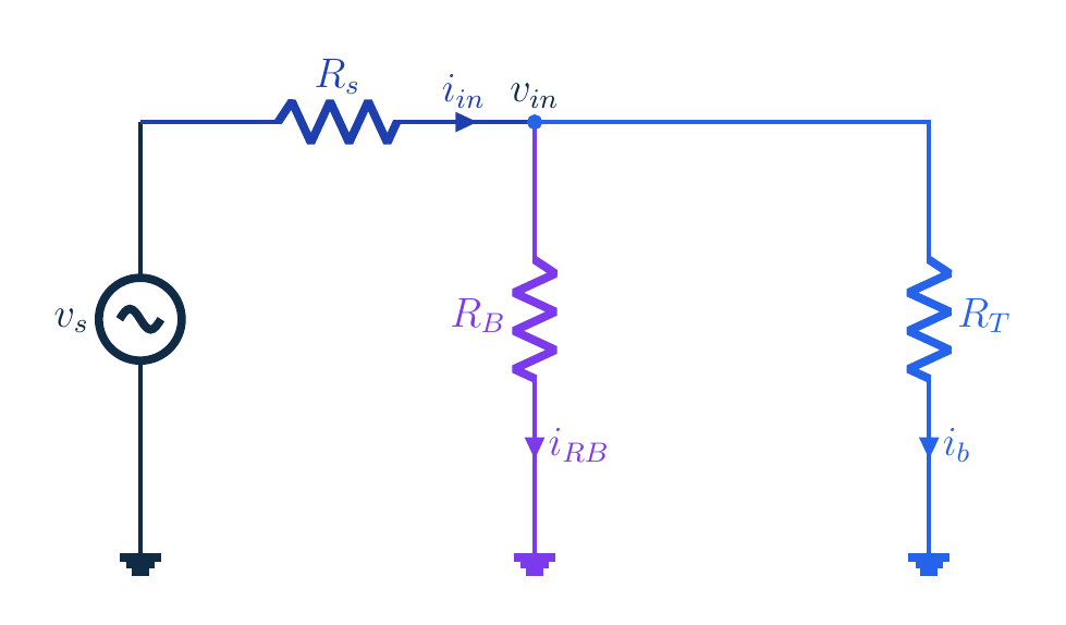
Original source visual. RT is a port equivalent, not an added physical resistor. Any animated panel loops forward independently of audio; current gauges share a scale. Transistor branch: RT=rπ+(β+1)RE; not total inputNarration transcript
First look into the transistor branch by itself. Emitter current equals beta plus one times base current. Input voltage is base current times r pi, plus emitter current times the external emitter resistance. Factoring out base current gives r pi plus beta plus one times emitter resistance. Call this branch resistance R T. It is the resistance looking into the transistor base branch, including emitter feedback. It is not yet the total amplifier input resistance, because the base bias resistor is still connected.
6. Two paths, one input voltage
iin=iRB+ib; never use βiin as collector currentNarration transcript
Now restore the other path. The base resistor and the transistor branch both connect between the input node and signal ground. The current through the base resistor is input voltage divided by R B. The current entering the transistor branch is input voltage divided by R T. The source supplies their sum. This is the important distinction: total input current is not base current. Multiplying total input current by beta would incorrectly amplify the current that bypasses the transistor through the bias resistor.
7. Two paths, one input voltage
Original source visual. RT is a port equivalent, not an added physical resistor. Any animated panel loops forward independently of audio; current gauges share a scale. Rin=RB ∥ RT < each positive finite branchRB → ∞ at fixed Q gives Rin → RT; removing real bias resistor changes QNarration transcript
Divide the input voltage by the total current. The two conductances add, giving input resistance equal to R B in parallel with R T. This total is smaller than either positive finite branch resistance. As R B becomes very large in a fixed-bias small signal model, its current becomes negligible and total input resistance approaches R T. That limiting calculation holds the operating point fixed; physically removing the resistor from this actual bias circuit would remove its base bias path and is not the same experiment.
8. Define the gain before using a formula
Stage gain uses actual base voltage:Av=−βRC/RT; do not put total Rin in this denominatorNarration transcript
Define stage gain using the actual voltage at the base input. A positive base current change increases collector current, increasing the drop across the collector resistor and lowering collector voltage. Output voltage is negative beta times base current times collector resistance. Divide by input voltage, which is base current times R T. The base current cancels and the gain is negative beta R C divided by R T. Do not replace R T with total input resistance here: the collector current depends on base current, not total source current.
9. Define the gain before using a formula
Original source visual. RT is a port equivalent, not an added physical resistor. Any animated panel loops forward independently of audio; current gauges share a scale. Av=−RC/(1/gm+(1+1/β)RE); high β drops 1/β onlyZero input, remove load, r_o → ∞:Narration transcript
Two compact results need their assumptions attached. Since r pi equals beta divided by g m, the exact denominator can be written one over g m plus one plus one over beta times emitter resistance. Only at high beta do we drop the one over beta term. For output resistance, remove the external load and zero the independent input signal. With infinite r o there is no feedback path from the collector test voltage into the transistor input, so output resistance is R C. Finite r o would change that result.
10. A complete supplemental example
Added example:VBE=0.7 V; VT=26 [mV]; source AC-coupled; verify DC before gmNarration transcript
The original note gives a symbolic derivation rather than a numerical amplifier problem. We now add a separate teaching example: a twelve volt supply, four hundred seventy kilohms at the base, two kilohms at the collector, and one kilohm at the emitter. Use beta one hundred, base emitter voltage zero point seven volts, and thermal voltage twenty six millivolts. Keep the signal source AC-coupled. Before using g m, find a valid direct current operating point; the bias resistor determines that current as well as loading the later signal input.
11. A complete supplemental example
IB≈19.79 [μA], not collector currentNarration transcript
Let us calculate the base current without hiding the denominator. The emitter current is beta plus one times the base current, so the emitter resistor contributes that same factor to the base loop. One hundred plus one, multiplied by one kilohm, gives one hundred one kilohms. Add the four hundred seventy kilohm base resistor: the total denominator is five hundred seventy one kilohms. The voltage available after the junction is twelve minus zero point seven, or eleven point three volts. Divide that voltage by the denominator. Volts divided by kilohms gives milliamps, so zero point zero one nine seven nine milliamps is nineteen point seven nine microamps. That is the base current, not the collector current.
12. A complete supplemental example
VE=IE RE≈1.999 V; keep guard digitsNarration transcript
Now carry that base current through the transistor relations. We keep the unrounded calculator value internally, although the display rounds the final results. Collector current is beta times base current: multiply one hundred by nineteen point seven eight nine eight four two microamps. The result is about one point nine seven nine milliamps. For emitter current use beta plus one instead, so multiply by one hundred one. This gives about one point nine nine nine milliamps. Emitter current is slightly larger because it includes the base current as well. Finally, multiply emitter current by the one kilohm emitter resistor. Milliamps times kilohms gives volts, so emitter voltage is about one point nine nine nine volts above ground.
13. A complete supplemental example
Original source visual. RT is a port equivalent, not an added physical resistor. Any animated panel loops forward independently of audio; current gauges share a scale. VCE≈6.043 V; VC>VB supports forward-active biasNarration transcript
Before we use a small signal model, check the voltages. Base voltage is the emitter voltage plus the assumed zero point seven volt junction drop. Adding them gives about two point six nine nine volts. Collector voltage is the supply minus the collector resistor drop. Multiply the unrounded collector current in milliamps by two kilohms, then subtract that drop from twelve volts. We obtain about eight point zero four two volts at the collector. Subtract emitter voltage from collector voltage and the collector emitter voltage is about six point zero four three volts. The collector is above the base, so the collector base junction is reverse biased. Together with our forward biased base emitter junction, that supports the assumed forward active operating region.
14. A complete supplemental example
Original source visual. RT is a port equivalent, not an added physical resistor. Any animated panel loops forward independently of audio; current gauges share a scale. gm=IC/VT≈0.076115 S=76.115 mSrπ=β/gm≈1313.805 Ω; transistor parameter, not RinNarration transcript
Use the verified collector current to calculate the small signal parameters. Transconductance g m is collector current divided by thermal voltage. Substitute zero point zero zero one nine seven eight nine eight four amperes and zero point zero two six volts. The quotient is about zero point zero seven six one one five siemens, which is seventy six point one one five millisiemens. Next, r pi is beta divided by g m. Divide one hundred by the unrounded transconductance in siemens. This gives about one thousand three hundred thirteen point eight zero five ohms, or one point three one four kilohms. These are operating point parameters of the transistor, not the total input resistance of the whole amplifier.
15. A complete supplemental example
Rin=470RT/(470+RT), using kΩ throughoutRin≈84.023 kΩ; below either branchNarration transcript
Now build the two input resistances separately. The transistor branch resistance R T is r pi plus beta plus one times the emitter resistor. We already calculated that emitter term as one hundred one kilohms. Add one point three one three eight zero five kilohms: the branch resistance is about one hundred two point three one four kilohms. The signal source also sees the four hundred seventy kilohm bias resistor in parallel. For two parallel resistors, multiply their resistances and divide by their sum. Using kilohms consistently, multiply four hundred seventy by one hundred two point three one three eight zero five, then divide by their sum. The total input resistance is about eighty four point zero two three kilohms. It is below either branch resistance, exactly as a parallel combination should be.
16. A complete supplemental example
Original source visual. RT is a port equivalent, not an added physical resistor. Any animated panel loops forward independently of audio; current gauges share a scale. Unloaded stage:RT governs collector current; source resistance and load not yet includedNarration transcript
For the unloaded collector, divide negative one hundred times two kilohms by R T. Stage gain is about negative one point nine five five. If you incorrectly use the eighty four kilohm total input resistance in that denominator, you predict too much collector response because some source current never enters the transistor. The stage gain formula is referenced to the base input voltage. It has not yet included a nonzero source resistance or an output load. Keep those definitions visible so the next extension does not silently change what gain means.
17. Add the source and load, then check the limits
Original source visual. RT is a port equivalent, not an added physical resistor. Any animated panel loops forward independently of audio; current gauges share a scale. AC-coupled RL=10 kΩ; RC ∥ RL≈1.667 kΩLoaded stage:Base-voltage reference; load coupling blocks DC, bias unchangedNarration transcript
Now add a ten kilohm collector load through a coupling capacitor. At midband, that capacitor acts approximately as a short, so the collector sees R C and R L in parallel. Multiply two by ten and divide by their sum, twelve. The effective collector load is about one point six six seven kilohms. Substitute this load into negative beta times the load, divided by R T. With beta one hundred and R T about one hundred two point three one four kilohms, loaded stage gain is about negative one point six two nine. This gain is measured from the base input, not from the signal source. The coupling capacitor blocks direct current, so this added load does not change our earlier bias calculation.
18. Add the source and load, then check the limits
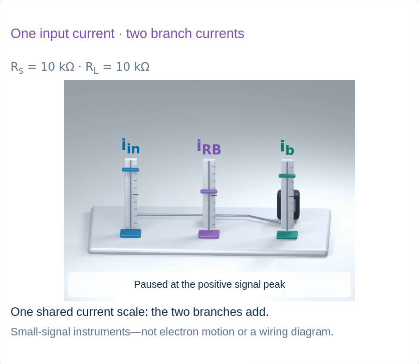
Original source visual. RT is a port equivalent, not an added physical resistor. Any animated panel loops forward independently of audio; current gauges share a scale. Rs=10 kΩ; input divider Rin/(Rs+Rin)≈0.894Source gain≈−1.456; load and source cause separate reductionsNarration transcript
Next give the source a ten kilohm resistance. It forms a voltage divider with total input resistance, not with R T alone. Divide eighty four point zero two three by ten plus eighty four point zero two three, using kilohms throughout. The fraction reaching the base is about zero point eight nine four. Source to output gain is loaded stage gain multiplied by this input fraction. Negative one point six two nine times zero point eight nine four gives about negative one point four five six. We retain unrounded values internally. There are two separate reductions: the collector load reduces stage gain, and source resistance reduces the input signal.
19. Add the source and load, then check the limits
ib=vin/RT≈8.734 nAiRB=vin/RB≈1.901 nA; neither alone is iinNarration transcript
Apply a one millivolt source change to this loaded circuit. Multiplying by the unrounded input fraction gives about zero point eight nine four millivolts at the base. Divide that input voltage by R T to get base branch current, and separately by R B to get bias resistor current. One millivolt divided by one kilohm is one microamp. Using the full precision input voltage and R T, then converting microamps to nanoamps, base current is about eight point seven three four nanoamps. Dividing the same voltage by four hundred seventy kilohms gives bias resistor current about one point nine zero one nanoamps. These are two distinct branches; neither current alone is the total source current.
20. Add the source and load, then check the limits
Original source visual. RT is a port equivalent, not an added physical resistor. Any animated panel loops forward independently of audio; current gauges share a scale. iin=ib+iRB≈10.636 nAMatches source gain; negative change is not negative total VCNarration transcript
Check the currents before calculating output. At the input node, add base current and bias resistor current: the sum is about ten point six three six nanoamps. At the collector, multiply only base current by beta, one hundred. The small signal collector current is about zero point eight seven three four three three microamps. A positive collector current change pulls the collector voltage downward through the effective load. Multiply negative zero point eight seven three four three three microamps by one point six six six six six seven kilohms. Microamps times kilohms gives millivolts, so the output change is about negative one point four five six millivolts. This matches our source gain times the one millivolt input source. The minus sign means inversion around the bias point, not that the full collector voltage is negative.
21. Add the source and load, then check the limits
Answer: source drives two parallel paths; Rin=RB ∥ RTStage gain uses ib; generator gain also includes attenuation and loadBias → DC/AC replacements → labeled currents; finite ro and capacitances need more modelNarration transcript
Return to the source's question. It drives two parallel paths, so amplifier input resistance is the base bias resistor in parallel with the transistor branch resistance. Stage gain uses base current and the actual base voltage. Gain from the generator also includes input attenuation, and a collector load changes the effective collector resistance. Begin with a valid bias point, mark the DC to AC replacements, and label each voltage and current before simplifying. Finite output resistance, transistor capacitances, large signals and changes in bias require a more complete model; none are erased by a compact gain formula.
Source video: Electronics Basics #35 | Two Input Paths: What Does the Signal Source Drive? (16:08)