Communication Basics · Doubling Fiber Distance: Link Budget and EDFA Limits
#29 calculate −30-dBm received power and 20-dB raw margin from a +1-dBm transmitter, two 0.5-dB connectors, 30-dB total installed-link fiber loss, −50-dBm receiver sensitivity, and a 15-dB required margin; under a uniform distributed-attenuation assumption, double fiber length to 60-dB fiber loss and −60-dBm received power; add an example 25-dB EDFA to obtain −35 dBm and then apply OSNR, ASE, saturation, dispersion, nonlinearity, and span acceptance gates
Calculate −30 dBm and 20 dB raw margin for the first link, then −60 dBm and a 25-dB requirement shortfall at double length; bound the 25-dB EDFA example with OSNR and span-design gates.
Question
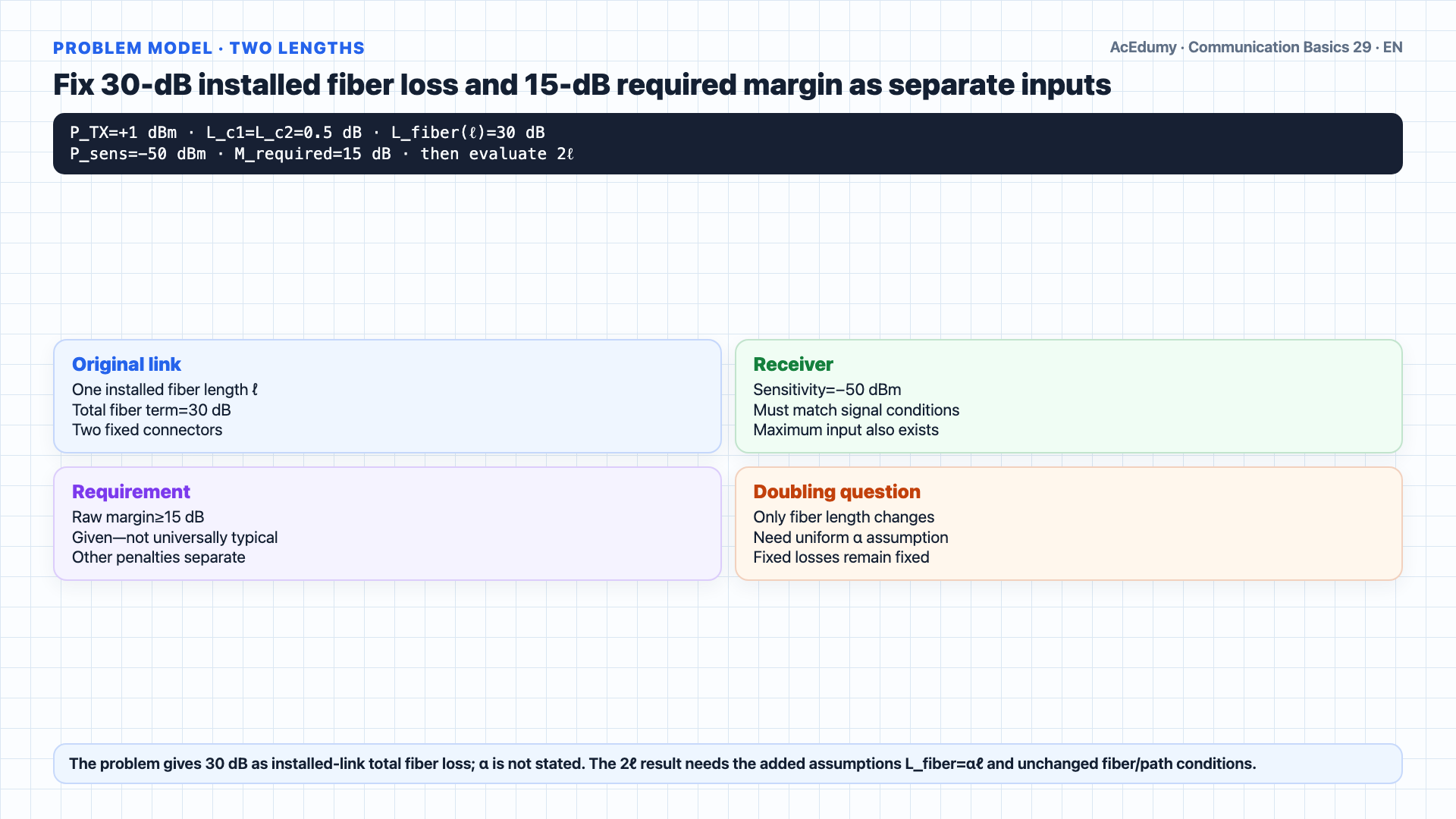
For the first link calculate P_RX=+1−0.5−30−0.5=−30 dBm=1 µW and M_raw=(−30)−(−50)=20 dB; state that only 5 dB residual slack remains above the given 15-dB requirement and that pass is limited to the minimum-power gate; do not infer the doubling result unless the installed 30-dB fiber loss is additionally assumed uniform and proportional to length; under that assumption only distributed fiber loss doubles 30→60 dB while connectors remain fixed, so the extra 30-dB attenuation reduces received power 1000× to −60 dBm; distinguish raw margin −10 dB, 10-dB sensitivity shortfall, and 25-dB shortfall to the required 15-dB margin; with an ideal midspan +25-dB amplifier calculate exact running levels −29.5→−4.5 dBm and final −35 dBm with 15-dB raw margin; show that this leaves zero residual slack to the requirement and is not an accepted EDFA design without insertion loss/gain tilt, wavelength band, input/output limits, saturation, noise figure/ASE, OSNR, dispersion, nonlinearities, safety, and end-of-life margin; do not make 25-dB gain or 80–100-km spacing universal rules; retain Raman/other optical amplification, regeneration, lower-loss fiber/path, modulation/FEC/rate, and architecture alternatives.
Written solution and narration transcript(shows the full solution)
Below are all the lines written in the notebook together with the full narration transcript.
1. Fix the model, 30-dB installed loss, and 15-dB requirement
Double only distributed fiber loss; do not treat the arithmetic recovery to exactly 15 dB of raw margin with a 25-dB EDFA as deployable optical-system acceptance. Welcome back.Today we revisit fiber optic link budgets, but with a twist that every real-world engineer runs into eventually: what happens when you try to stretch the link further?Here is the setup.A laser transmitter outputs one dBm of optical power.Its output passes through a connector into the fiber, losing zero point five decibels.The fiber itself contributes a total of thirty decibels of loss.Notice we are not given a per-kilometer figure this time — just the total accumulated loss for the link as installed.At the far end another connector loses another zero point five decibels before the light reaches the receiver.The receiver's sensitivity threshold is negative fifty dBm.Four questions.Part a: find the optical power at the receiver.Part b: assuming a fifteen decibel margin is enough for reliable operation, does this link work?Part c: what if we doubled the distance, keeping every other component the same?Part d: would that doubled link still operate?Narration transcript
Welcome back. Today we revisit fiber optic link budgets, but with a twist that every real-world engineer runs into eventually: what happens when you try to stretch the link further? Here is the setup. A laser transmitter outputs one d B m of optical power. Its output passes through a connector into the fiber, losing zero point five decibels. The fiber itself contributes a total of thirty decibels of loss. Notice we are not given a per-kilometer figure this time — just the total accumulated loss for the link as installed. At the far end another connector loses another zero point five decibels before the light reaches the receiver. The receiver's sensitivity threshold is negative fifty d B m. Four questions. Part a: find the optical power at the receiver. Part b: assuming a fifteen decibel margin is enough for reliable operation, does this link work? Part c: what if we doubled the distance, keeping every other component the same? Part d: would that doubled link still operate?
2. Re-establish dB loss-magnitude and dBm level signs
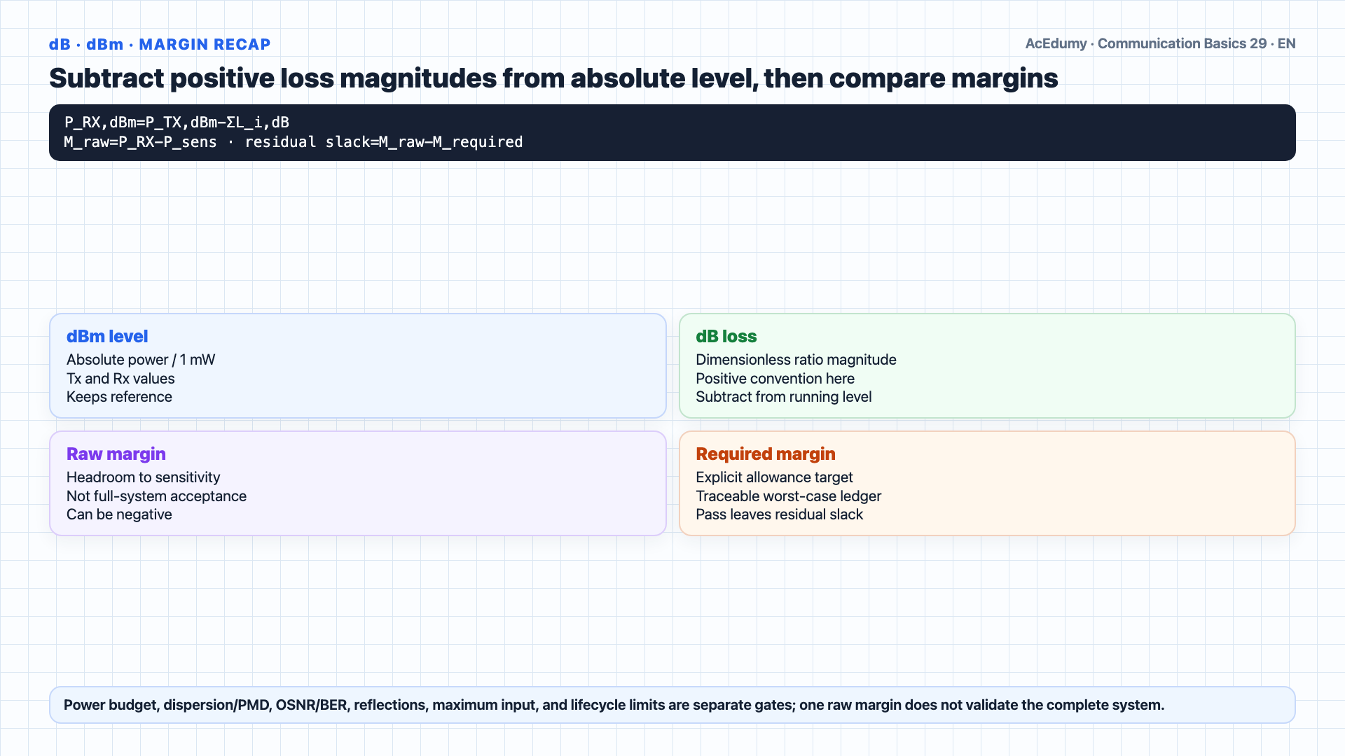
Double only distributed fiber loss; do not treat the arithmetic recovery to exactly 15 dB of raw margin with a 25-dB EDFA as deployable optical-system acceptance. A quick reminder before we start.Every element in the chain is expressed in decibels — either as an absolute power in dBm at the source, or as a relative loss in dB for the cable, the connectors, and the fiber.The trick of dB is that multiplication in linear power becomes addition in dB.So as the photon walks from laser to receiver, we just add the dBm output and subtract every dB loss along the way.Whatever number we end up with — that is the received power, in dBm.Margin is then a simple subtraction: received power minus the receiver's sensitivity threshold.Narration transcript
A quick reminder before we start. Every element in the chain is expressed in decibels — either as an absolute power in d B m at the source, or as a relative loss in d B for the cable, the connectors, and the fiber. The trick of d B is that multiplication in linear power becomes addition in d B. So as the photon walks from laser to receiver, we just add the d B m output and subtract every d B loss along the way. Whatever number we end up with — that is the received power, in d B m. Margin is then a simple subtraction: received power minus the receiver's sensitivity threshold.
3. Calculate −30 dBm, or 1 µW, at the receiver
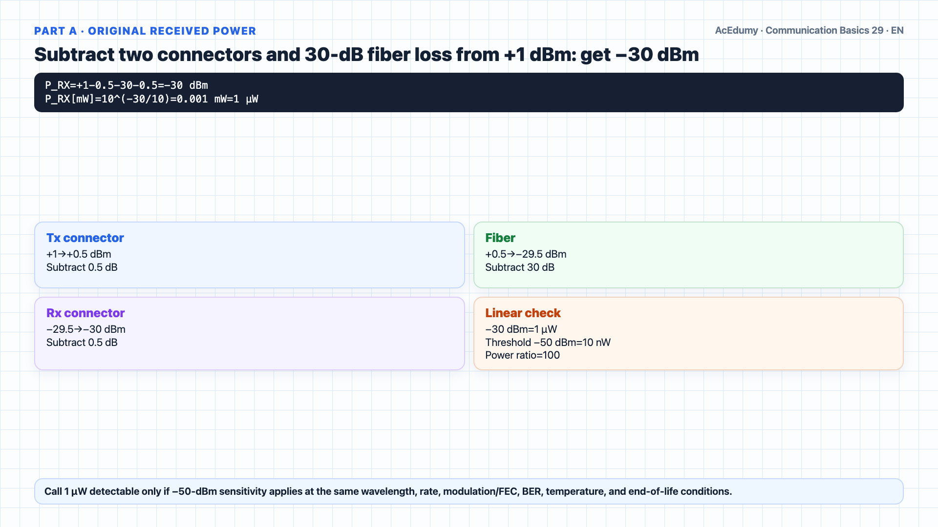
Double only distributed fiber loss; do not treat the arithmetic recovery to exactly 15 dB of raw margin with a 25-dB EDFA as deployable optical-system acceptance. Part a: optical power at the receiver.Start at one dBm at the laser.Subtract zero point five for the first connector.Zero point five dBm.Subtract thirty for the fiber.Negative twenty nine point five dBm.Subtract zero point five for the second connector.Negative thirty dBm.Received power is negative thirty dBm.−30 dBm=1 µW; detectability follows only if the −50-dBm sensitivity applies at the same wavelength, rate, format, BER/FEC, temperature, and end-of-life conditions.Narration transcript
Part a: optical power at the receiver. Start at one d B m at the laser. Subtract zero point five for the first connector. Zero point five d B m. Subtract thirty for the fiber. Negative twenty nine point five d B m. Subtract zero point five for the second connector. Negative thirty d B m. Received power is negative thirty d B m. That is one microwatt — small, but well within the detection range of a sensitive optical receiver.
4. Compare 20-dB raw margin with 15-dB requirement and 5-dB slack
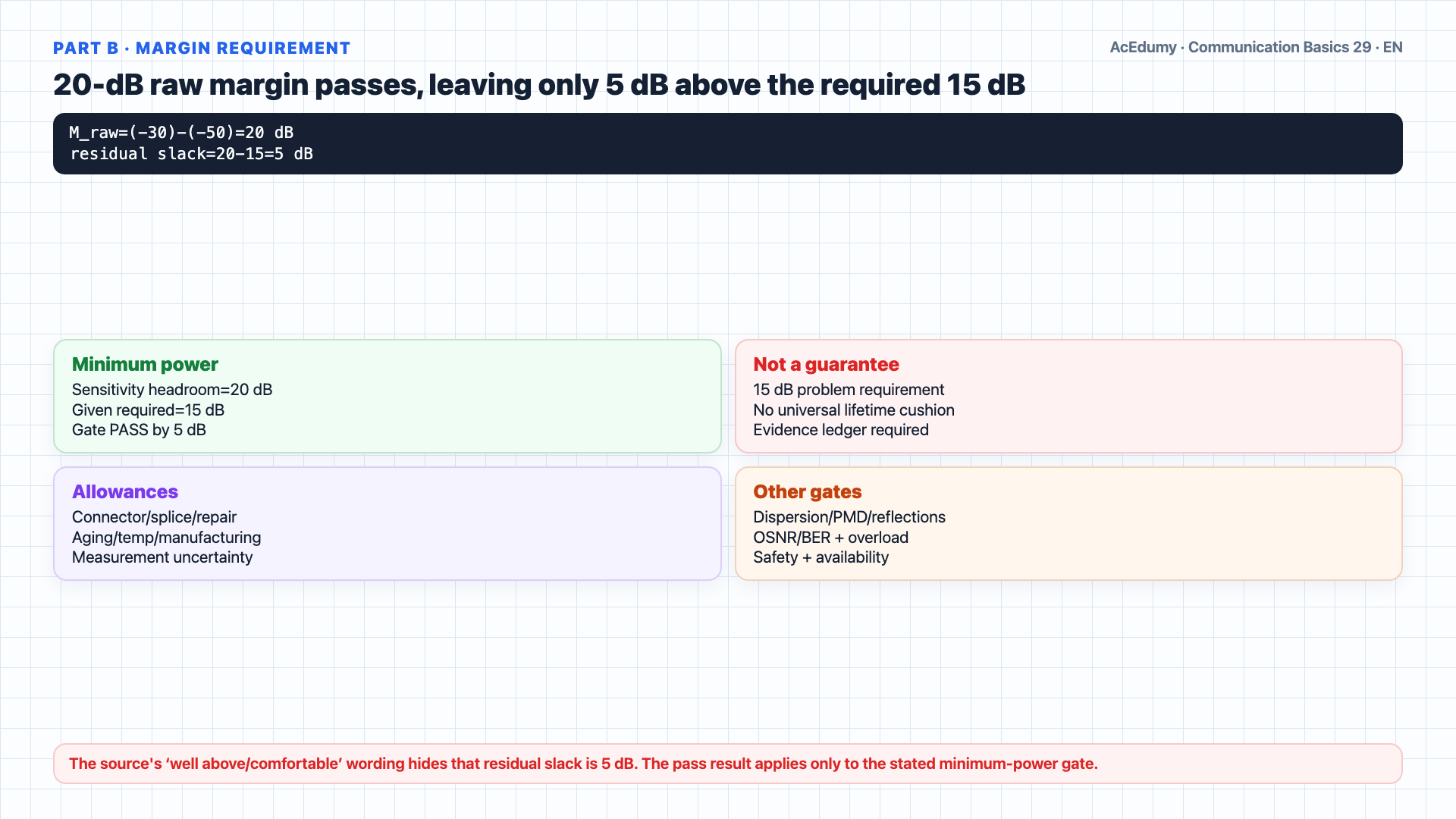
Double only distributed fiber loss; do not treat the arithmetic recovery to exactly 15 dB of raw margin with a 25-dB EDFA as deployable optical-system acceptance. Part b: does the link work?Margin equals received power minus the sensitivity threshold.Negative thirty dBm minus negative fifty dBm equals twenty decibels.A 20-dB raw margin is 5 dB above the problem's stated 15-dB minimum requirement.Thus the stated minimum-power margin gate passes; overload, dispersion/PMD, reflections, BER/OSNR, and lifecycle gates must also pass.But why fifteen decibels?Because real fiber links degrade with time and conditions.Connectors get dirty.Splices age.Temperature swings expand and contract the cable.Manufacturing tolerances mean that not every fiber spool delivers exactly zero point three decibels per kilometer.15 dB is the explicit required margin in this problem; real allowances derive from vendor worst-case/EOL specifications, splice/repair/connector ledgers, measurement uncertainty, and path penalties—not a universal cushion or lifetime guarantee.Narration transcript
Part b: does the link work? Margin equals received power minus the sensitivity threshold. Negative thirty d B m minus negative fifty d B m equals twenty decibels. Twenty decibels is well above the fifteen decibel requirement. So yes — the link operates. But why fifteen decibels? Because real fiber links degrade with time and conditions. Connectors get dirty. Splices age. Temperature swings expand and contract the cable. Manufacturing tolerances mean that not every fiber spool delivers exactly zero point three decibels per kilometer. Engineers reserve a chunk of margin to absorb these variations — fifteen decibels is the typical cushion that gives you a working link for the lifetime of the installation, not just on the day it was commissioned.
5. Condition distance doubling on uniform distributed attenuation
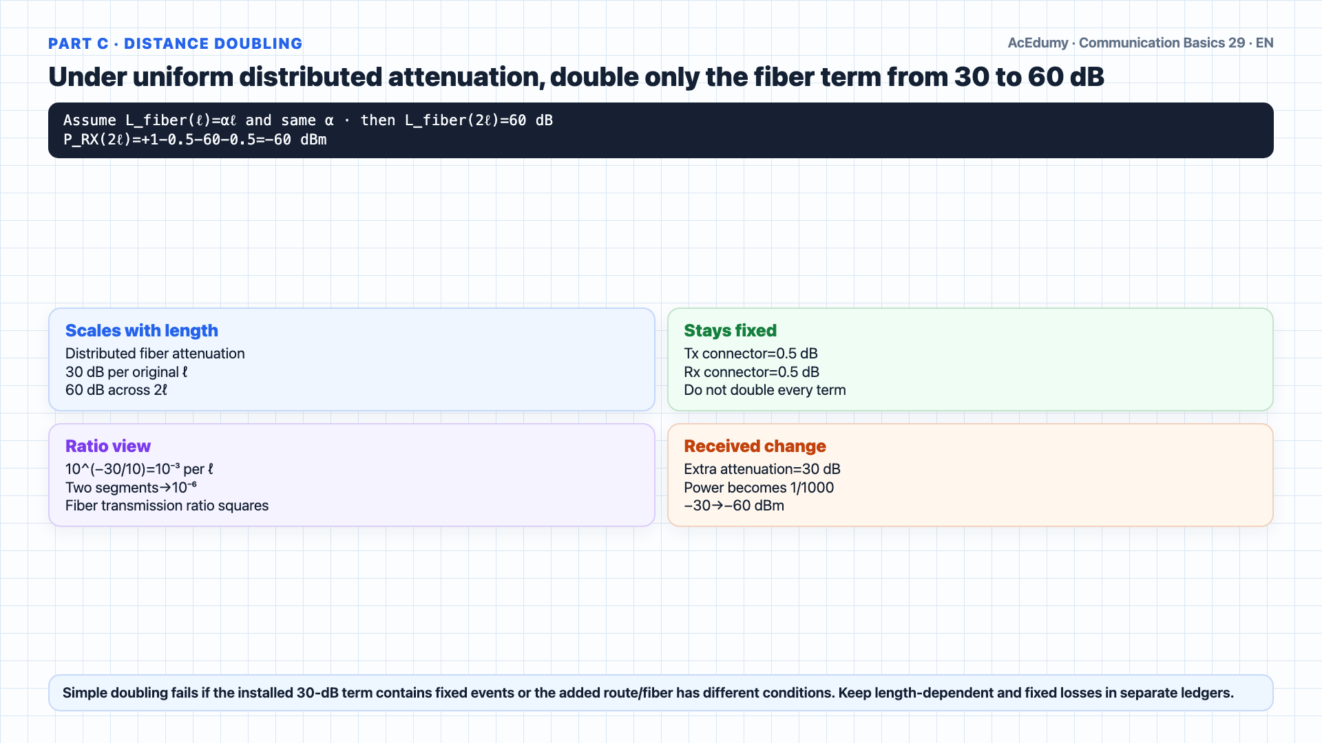
Double only distributed fiber loss; do not treat the arithmetic recovery to exactly 15 dB of raw margin with a 25-dB EDFA as deployable optical-system acceptance. Part c — and this is the real lesson.What if we doubled the link distance?Same laser, same connectors, same receiver — only the fiber length changes.Here is the conditional model: assume the installed 30-dB fiber loss is uniform and proportional to length under the same fiber/path conditions.Although no α is given, additionally assume distributed fiber attenuation follows Lfiber=αℓ and that the 30-dB fiber term contains no fixed/non-distributed loss.Under that assumption, only distributed fiber loss doubles with length; connector and other fixed loss terms remain unchanged.Thirty decibels becomes sixty decibels.Notice the link distance grew linearly, by a factor of two.And the loss in dB also grew linearly, by a factor of two.Cascading two equal fiber segments under the same attenuation coefficient squares the fiber transmission ratio: 10(−30/10)→10(−60/10).The extra 30 dB of fiber attenuation reduces received optical power by 10(30/10)=1000 relative to the first link; this follows from the uniform-loss model.Now the budget.One dBm, minus zero point five, minus sixty, minus zero point five, equals negative sixty dBm.Received power crashes from negative thirty all the way down to negative sixty.Narration transcript
Part c — and this is the real lesson. What if we doubled the link distance? Same laser, same connectors, same receiver — only the fiber length changes. Here is the key idea. Fiber loss is per kilometer. Double the kilometers, you double the total decibels of loss. Thirty decibels becomes sixty decibels. Notice the link distance grew linearly, by a factor of two. And the loss in d B also grew linearly, by a factor of two. But d B is a logarithmic scale — so the linear power loss is squared. Doubling distance does not just cost you twice as much power — it costs you a thousand times more, in linear units. Now the budget. One d B m, minus zero point five, minus sixty, minus zero point five, equals negative sixty d B m. Received power crashes from negative thirty all the way down to negative sixty.
6. Separate −10-dB raw margin from the 25-dB requirement shortfall
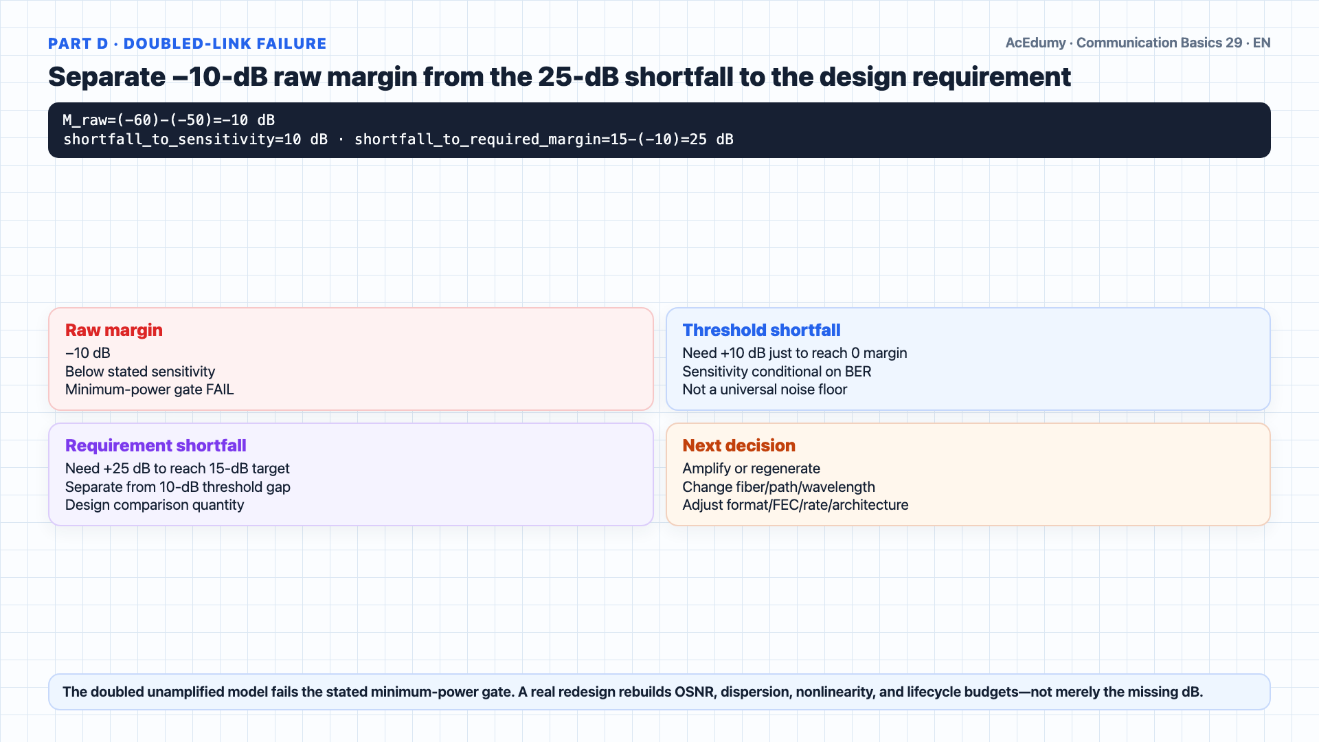
Double only distributed fiber loss; do not treat the arithmetic recovery to exactly 15 dB of raw margin with a 25-dB EDFA as deployable optical-system acceptance. Part d.With negative sixty dBm at the receiver, can the link still operate?Margin equals negative sixty minus negative fifty, which is negative ten decibels.Raw margin is −10 dB, or 10 dB below stated sensitivity; the total shortfall to the 15-dB required margin is 25 dB, and sensitivity operating conditions must still match.Forget the fifteen decibel cushion; we cannot even meet zero.The doubled unamplified model fails the stated minimum-power gate; this conclusion is scoped to the specified threshold and conditions.Narration transcript
Part d. With negative sixty d B m at the receiver, can the link still operate? Margin equals negative sixty minus negative fifty, which is negative ten decibels. A negative margin means we are below the sensitivity threshold — the light arriving at the photodetector is weaker than the receiver can reliably distinguish from noise. Forget the fifteen decibel cushion; we cannot even meet zero. The link does not operate.
7. Bound the 25-dB EDFA example with −35 dBm, OSNR, and span gates
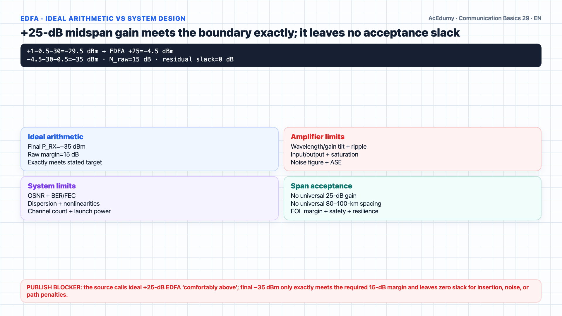
Double only distributed fiber loss; do not treat the arithmetic recovery to exactly 15 dB of raw margin with a 25-dB EDFA as deployable optical-system acceptance. So how do we extend a real fiber link beyond its passive limit?We add an optical amplifier in the middle.EDFA is a common amplifier class for links in erbium gain bands; wavelength plan and application may instead use Raman/other amplification or regeneration.Inside the amplifier is a short section of erbium doped fiber pumped by a separate laser, typically at nine eighty or fourteen eighty nanometers.EDFA provides optical-domain gain through stimulated emission, but also produces amplified spontaneous emission; increased signal power does not preserve OSNR automatically.+25 dB is the assumed amplifier gain for this worked example; real gain depends on wavelength/channel, input level, pump, saturation, gain flatness, and operating point.Exact ideal chain: −29.5 dBm after the first half, −4.5 dBm after +25-dB EDFA, and −35 dBm after the second half plus final connector; raw margin is exactly 15 dB with zero residual slack to the requirement.80–100 km can be a representative span range; spacing follows fiber/span loss, amplifier gain/input/output/noise figure, OSNR, channel count, dispersion, nonlinearities, safety, availability, and end-of-life design.Three takeaways from this video.One: uniform distributed fiber loss scales linearly with length; distance doubling doubles only length-dependent terms, not fixed connector/component losses.For passive reach extension, evaluate lower-loss route/fiber, wavelength, launch power within safety/nonlinear limits, modulation/FEC/rate, and architecture trade-offs; cost is requirement-dependent.Two: 15 dB is the problem requirement here; real margin comes from a quantified uncertainty, degradation, repair, and path-penalty ledger.Add aging, contamination, temperature, and installation variation using measured or qualified worst-case values; one number does not guarantee lifetime performance.Three: when passive budget fails, evaluate optical amplification, regeneration, or link/format redesign; EDFA is an important enabling component of long-haul/submarine systems, not the complete transoceanic system.Narration transcript
So how do we extend a real fiber link beyond its passive limit? We add an optical amplifier in the middle. The most common is the erbium doped fiber amplifier, or E D F A. Inside the amplifier is a short section of erbium doped fiber pumped by a separate laser, typically at nine eighty or fourteen eighty nanometers. Signal photons stimulate the excited erbium atoms to emit more identical photons — the signal gets stronger as it passes through, with no need to convert to electrical first. A typical E D F A delivers around twenty five decibels of gain. Drop one in the middle of our doubled link, and the second half of the fiber starts not from negative thirty d B m but from negative five — comfortably back above the receiver threshold at the far end. In long-haul backbones, amplifiers are spaced every eighty to one hundred kilometers. Three takeaways from this video. One: distance is linear, but cumulative d B loss is also linear — so doubling the link doubles every loss term in the budget. There is no cheap way to stretch passive fiber. Two: the fifteen decibel margin is not paranoia, it is engineering. It pays for aging, dirt, temperature, and the day-to-day variability of the installation. Three: when distance exceeds the passive budget, amplification is the answer — and the E D F A is what made transoceanic fiber possible.
Source video: Communication Basics #29 Worked Example: Doubling the Distance — Fiber Limits and the EDFA (6:51)