Communication Basics · Fiber-Optic Link Budget: 100 km, −22 dBm, and 38 dB Raw Margin
#27 calculate the ideal attenuation-only 100-km link budget for a +10-dBm transmitter, two 1-dB connectors, 0.3-dB/km fiber, and a −60-dBm receiver threshold; distinguish signed transfer gain from positive loss magnitude, bound the 180-km ideal loss-limited length, and apply sensitivity, overload, dispersion, OSNR, and lifecycle gates to the 300/50-km designs
Calculate −22 dBm received power and 38 dB raw margin for a 100-km fiber link, get the dB signs right, and bound the 180/300/50-km conclusions with real optical acceptance gates.
Question

Starting with P_out=P_in×G, define signed transfer gain g_dB=10log10(G)≤0 so P_out,dBm=P_in,dBm+g_dB, and distinguish the positive loss magnitude L_dB=−g_dB≥0 form P_out,dBm=P_in,dBm−L_dB; for 100 km calculate total loss=1+30+1=32 dB, P_rx=−22 dBm≈6.31 µW, and raw threshold margin=38 dB≈6309.6 ratio; solve 180 km for a 14-dB target raw margin but do not call it deployable reach because dispersion/PMD, splices, repair allowance, reflections, path penalties, aging, wavelength, and component worst cases are excluded; reject 300 km at a 22-dB raw shortfall and require OSNR and dispersion budgets for amplifier/regenerator designs; do not accept 50 km until −7 dBm is checked against receiver overload; do not apply a universal 10–20-dB margin or over-engineered/wasteful conclusion.
Written solution and narration transcript(shows the full solution)
Below are all the lines written in the notebook together with the full narration transcript.
1. Fix the problem inputs, wavelength, and acceptance scope
Verify the arithmetic without treating raw threshold headroom as deployable engineering margin, and do not accept the 50-km link before checking receiver overload. Welcome back.Today a fiber optic link budget — the same kind of engineering accounting we did for microwave, but now with light travelling through glass.Here is the setup.A laser transmitter outputs ten dBm of optical power.Its output goes through a connector into the fiber, which loses one decibel.The fiber itself is one hundred kilometers long and attenuates zero point three decibels per kilometer.At the far end another connector loses another one decibel before the light reaches the receiver.The receiver's sensitivity threshold is negative sixty dBm.We have five questions.Part a: find the optical power delivered to the receiver.Part b: compute the power margin.Part c: find the maximum fiber length that still gives a fourteen decibel margin.Part d: will a three hundred kilometer link work?Part e: would a fifty kilometer link be a good design choice?Narration transcript
Welcome back. Today a fiber optic link budget — the same kind of engineering accounting we did for microwave, but now with light travelling through glass. Here is the setup. A laser transmitter outputs ten d B m of optical power. Its output goes through a connector into the fiber, which loses one decibel. The fiber itself is one hundred kilometers long and attenuates zero point three decibels per kilometer. At the far end another connector loses another one decibel before the light reaches the receiver. The receiver's sensitivity threshold is negative sixty d B m. We have five questions. Part a: find the optical power delivered to the receiver. Part b: compute the power margin. Part c: find the maximum fiber length that still gives a fourteen decibel margin. Part d: will a three hundred kilometer link work? Part e: would a fifty kilometer link be a good design choice?
2. Derive dB/dBm arithmetic with signed gain and positive loss
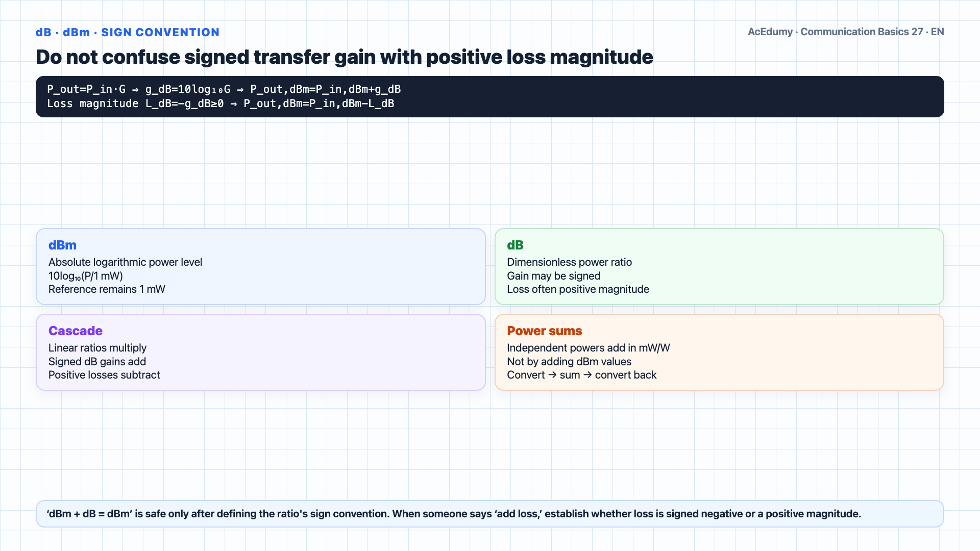
Verify the arithmetic without treating raw threshold headroom as deployable engineering margin, and do not accept the 50-km link before checking receiver overload. Before we plug in numbers, let me show you exactly why the dB arithmetic works.This is the proof that explains why dB m minus dB plus dB gives dB m.In the linear world, a cable or a connector does something simple: output power equals input power times a loss factor.If a connector lets eighty percent of light through, output equals input times zero point eight.Pure multiplication.Now take ten times the log base ten of both sides.Log of a product is the sum of logs.So ten log of output equals ten log of input plus ten log of loss factor.With signed transfer gain gdB=10log10(Pout/Pin)≤0, Pout,dBm=Pin,dBm+gdB; with positive loss magnitude LdB=−gdB≥0, Pout,dBm=Pin,dBm−LdB.Multiplication in linear becomes addition in dB.That is the whole trick.Now about units.dBm is defined as ten log of power divided by one milliwatt.It is a log of a ratio — but referenced to an absolute, one milliwatt.So dBm already is power in log form.dB by itself, like a cable loss, is ten log of a dimensionless ratio.Add them: dBm plus dB equals ten log of power ratio plus ten log of another ratio, equals ten log of the product — still dBm.Subtract: same thing in reverse.The units stay absolute because the reference milliwatt never disappeared.One warning: linear power and logarithmic level/ratio cannot be added as if they shared one representation.Convert every term to a compatible linear or logarithmic representation before operating on it.Ten milliwatts minus fourteen dB is nonsense — one is a power, the other is a log.If you need to convert, go back to linear first, then do the math.Now we apply this to the fiber link.Narration transcript
Before we plug in numbers, let me show you exactly why the d B arithmetic works. This is the proof that explains why dB m minus dB plus dB gives dB m. In the linear world, a cable or a connector does something simple: output power equals input power times a loss factor. If a connector lets eighty percent of light through, output equals input times zero point eight. Pure multiplication. Now take ten times the log base ten of both sides. Log of a product is the sum of logs. So ten log of output equals ten log of input plus ten log of loss factor. In d B notation, that is simply: output in d B equals input in d B plus loss in d B. Multiplication in linear becomes addition in d B. That is the whole trick. Now about units. d B m is defined as ten log of power divided by one milliwatt. It is a log of a ratio — but referenced to an absolute, one milliwatt. So d B m already is power in log form. d B by itself, like a cable loss, is ten log of a dimensionless ratio. Add them: d B m plus d B equals ten log of power ratio plus ten log of another ratio, equals ten log of the product — still d B m. Subtract: same thing in reverse. The units stay absolute because the reference milliwatt never disappeared. One warning. You can never mix linear and d B. Ten milliwatts minus fourteen d B is nonsense — one is a power, the other is a log. If you need to convert, go back to linear first, then do the math. Now we apply this to the fiber link.
3. Calculate the 32-dB loss through fiber and two connectors
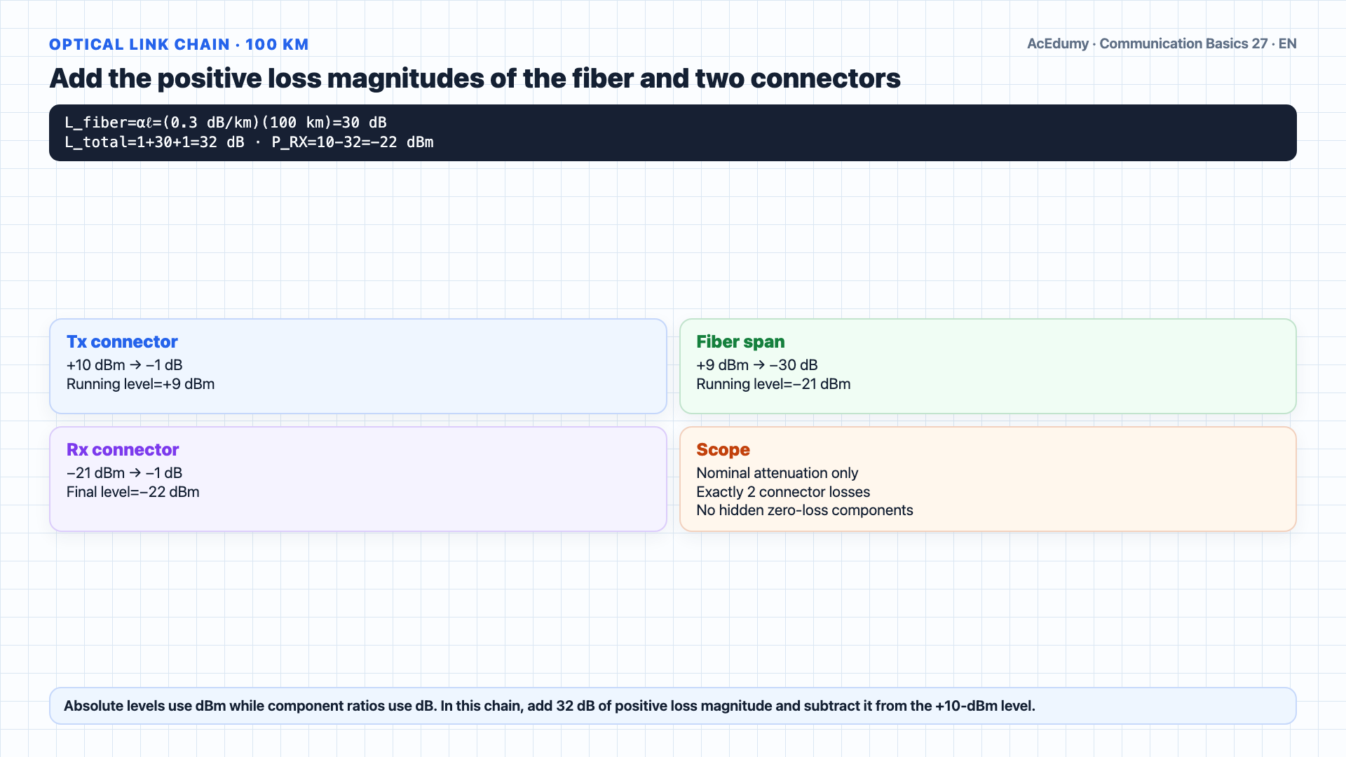
Verify the arithmetic without treating raw threshold headroom as deployable engineering margin, and do not accept the 50-km link before checking receiver overload. Here is the full link laid out.Transmitter: laser at plus ten dBm.Immediately the light passes through the laser to fiber connector — minus one dB.Then it enters the fiber, one hundred kilometers of glass.At zero point three decibels per kilometer, total fiber attenuation equals zero point three times one hundred, which is thirty decibels of loss.At the far end, another connector couples the light out of the fiber into the receiver — another minus one dB.Absolute optical-power levels are in dBm and component gain/loss ratios are in dB; add signed gains or subtract positive loss magnitudes.And that is how every optical link budget is read — like a running total from laser to receiver.Narration transcript
Here is the full link laid out. Transmitter: laser at plus ten d B m. Immediately the light passes through the laser to fiber connector — minus one d B. Then it enters the fiber, one hundred kilometers of glass. At zero point three decibels per kilometer, total fiber attenuation equals zero point three times one hundred, which is thirty decibels of loss. At the far end, another connector couples the light out of the fiber into the receiver — another minus one d B. Everything in d B, everything adds up. And that is how every optical link budget is read — like a running total from laser to receiver.
4. Find −22 dBm, approximately 6.31 µW, at the receiver
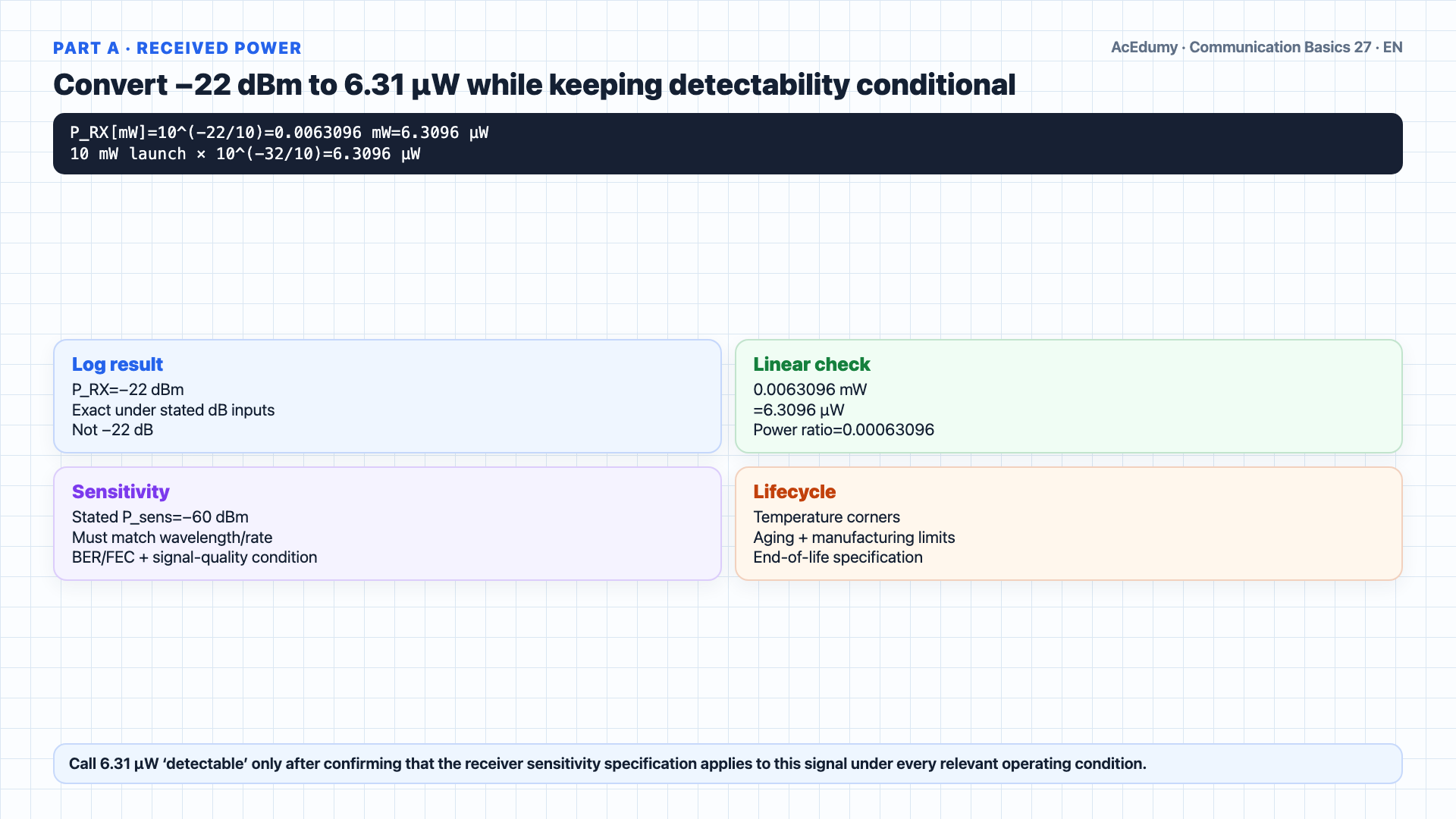
Verify the arithmetic without treating raw threshold headroom as deployable engineering margin, and do not accept the 50-km link before checking receiver overload. Part a: optical power at the receiver.Start with ten dBm.Subtract one dB for the laser connector.Nine dBm.Subtract thirty dB for the fiber.Negative twenty one dBm.Subtract one dB for the receiver connector.Negative twenty two dBm.Received power equals negative twenty two dBm.−22 dBm≈6.31 µW; detectability follows only if the stated −60-dBm threshold applies at the same wavelength, data rate, modulation, BER/FEC, temperature, and end-of-life conditions.Narration transcript
Part a: optical power at the receiver. Start with ten d B m. Subtract one d B for the laser connector. Nine d B m. Subtract thirty d B for the fiber. Negative twenty one d B m. Subtract one d B for the receiver connector. Negative twenty two d B m. Received power equals negative twenty two d B m. That is about six microwatts reaching the photodetector — way down from ten milliwatts at the laser, but absolutely detectable with a sensitive receiver.
5. Separate 38-dB raw threshold headroom from required margin
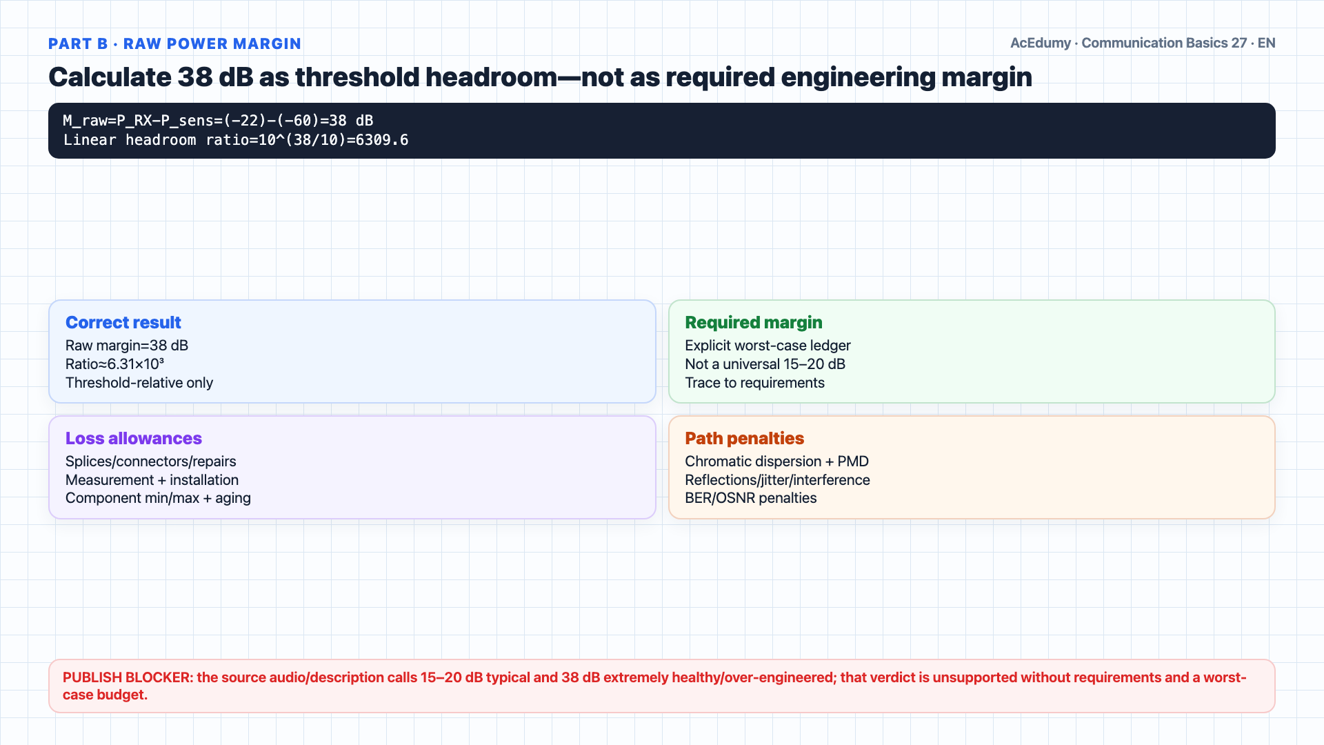
Verify the arithmetic without treating raw threshold headroom as deployable engineering margin, and do not accept the 50-km link before checking receiver overload. Part b: the power margin.Margin is the difference between what we have and what the receiver needs.Margin equals received power minus sensitivity threshold.Negative twenty two dBm minus negative sixty dBm.That is thirty eight decibels of margin.Thirty eight dB is a factor of about six thousand in linear power.38 dB is raw headroom to the stated sensitivity threshold; required design margin is derived from vendor worst cases, aging, temperature, splices, repair, measurement, and path penalties—not a universal 15–20-dB rule.Narration transcript
Part b: the power margin. Margin is the difference between what we have and what the receiver needs. Margin equals received power minus sensitivity threshold. Negative twenty two d B m minus negative sixty d B m. That is thirty eight decibels of margin. Thirty eight d B is a factor of about six thousand in linear power. In fiber engineering, fifteen to twenty d B is typical, so thirty eight d B is an extremely healthy margin — the link is well over engineered for this distance.
6. Solve and bound the 180-km ideal loss-limited length
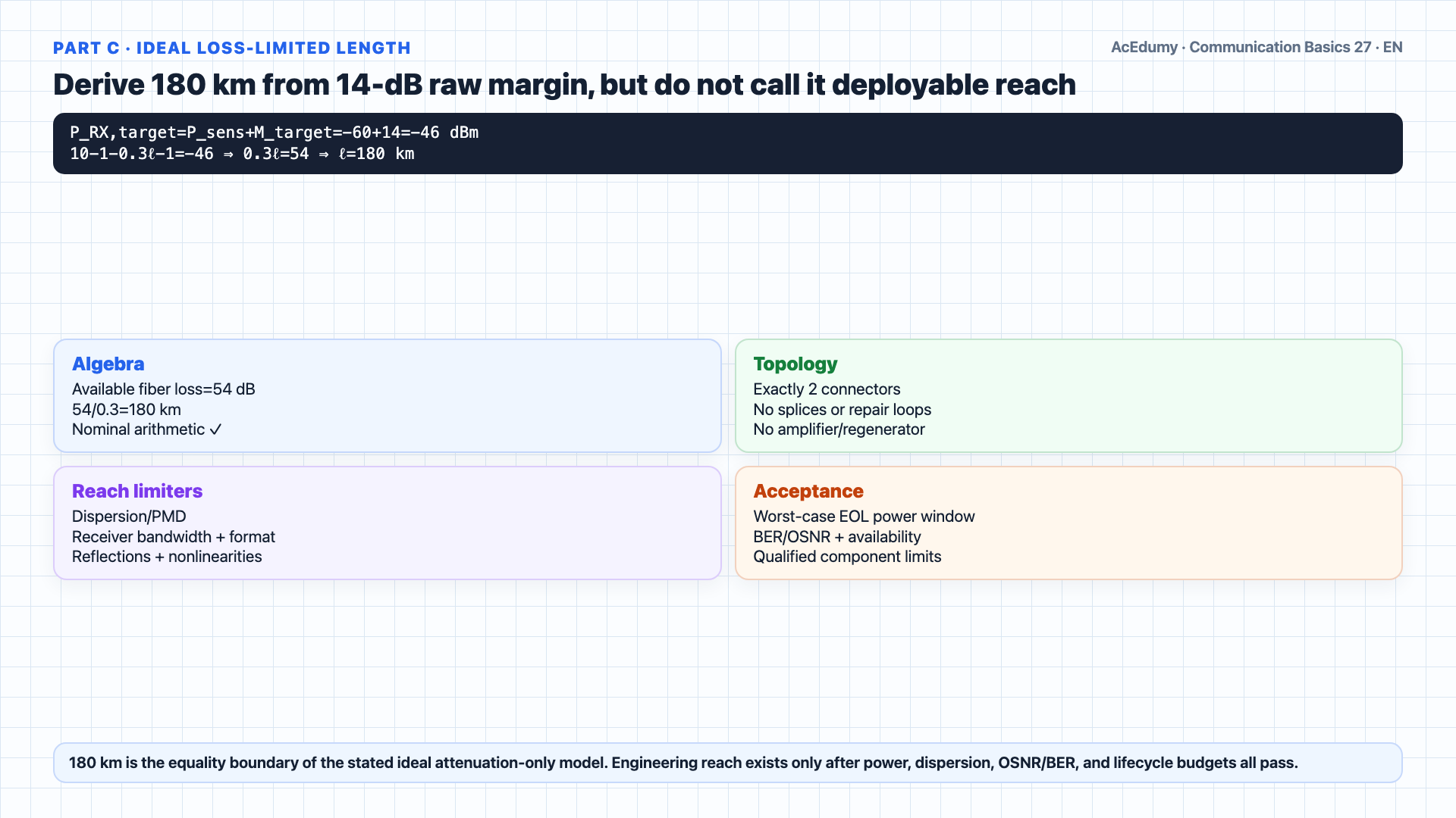
Verify the arithmetic without treating raw threshold headroom as deployable engineering margin, and do not accept the 50-km link before checking receiver overload. Part c: how far can the fiber go and still keep a fourteen decibel margin?We target a received power of negative forty six dBm — that is the threshold, negative sixty, plus the desired fourteen dB margin.Now we set up the budget.Laser output minus the two connectors minus fiber loss equals target power.Ten minus one minus zero point three times length minus one equals negative forty six.Rearrange: zero point three times length equals ten minus one minus one minus negative forty six, which is fifty four.Length equals fifty four divided by zero point three, which equals one hundred eighty kilometers.180 km is only an ideal attenuation-only limit using α=0.3 dB/km and exactly two 1-dB connectors; dispersion/PMD, splices, repairs, reflections, nonlinearities, and component worst cases are excluded.Almost double the original hundred kilometers.Narration transcript
Part c: how far can the fiber go and still keep a fourteen decibel margin? We target a received power of negative forty six d B m — that is the threshold, negative sixty, plus the desired fourteen d B margin. Now we set up the budget. Laser output minus the two connectors minus fiber loss equals target power. Ten minus one minus zero point three times length minus one equals negative forty six. Rearrange: zero point three times length equals ten minus one minus one minus negative forty six, which is fifty four. Length equals fifty four divided by zero point three, which equals one hundred eighty kilometers. So this system can support up to one hundred eighty kilometers of fiber while still having the fourteen d B safety cushion. Almost double the original hundred kilometers.
7. Test 300-km shortfall and 50-km receiver overload risk
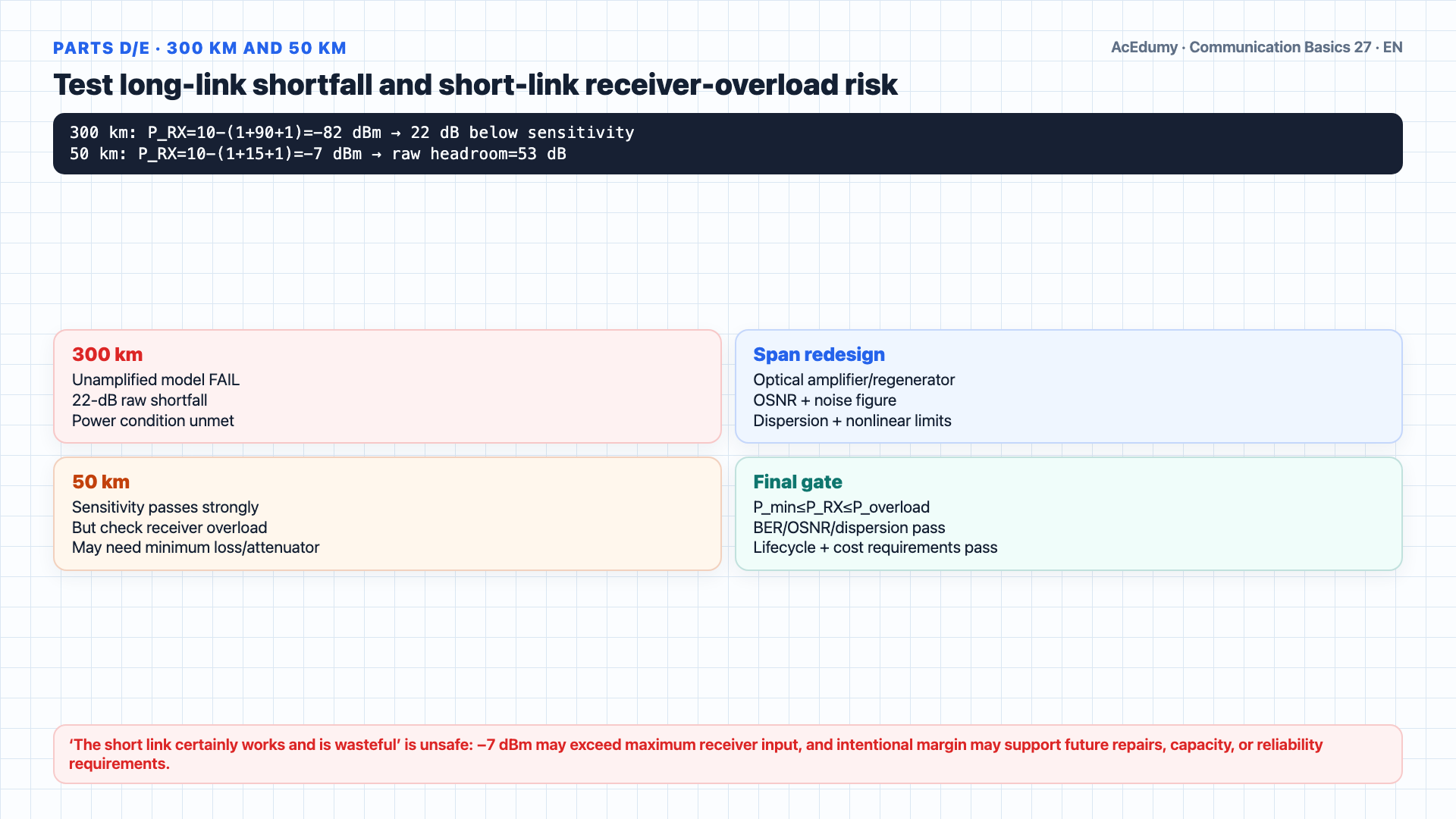
Verify the arithmetic without treating raw threshold headroom as deployable engineering margin, and do not accept the 50-km link before checking receiver overload. Parts d and e — quick judgements, then three takeaways.Part d: three hundred kilometers?Zero point three times three hundred is ninety decibels of fiber loss alone.Plus two decibels of connectors is ninety two.Ten dBm minus ninety two is negative eighty two dBm — far below the negative sixty threshold.The link does not operate.The 300-km case has a 22-dB raw shortfall; optical amplifiers, regenerators, or different span/fiber/format choices also require OSNR, noise-figure, dispersion, nonlinearity, and safety budgets.Part e: fifty kilometers?Loss is only fifteen decibels of fiber plus two of connectors, seventeen total.Received power would be −7 dBm with 53 dB of raw threshold headroom; this input may exceed the receiver overload/max-input limit and may require minimum path loss or an attenuator.Accept the link only when sensitivity, overload/dynamic range, BER, wavelength, dispersion, and lifecycle limits all pass; cost/value cannot be inferred without requirements.Select components against the full power window, capacity, availability, repair/future-growth allowance, lifecycle, and cost objectives—not distance alone.Three takeaways.One: every element in a fiber link is a dB addition or subtraction.Start with transmit power, walk through the chain, end with received power.Two: margin is a traceable acceptance requirement built from explicit worst-case losses and allowances, not a verdict by itself.Budget aging, temperature, and manufacturing variation from quantified component/path limits; 10–20 dB is not a universal sufficiency guarantee.Three: match hardware to minimum/maximum received power, OSNR, dispersion, BER/availability, lifecycle, and cost requirements together.Narration transcript
Parts d and e — quick judgements, then three takeaways. Part d: three hundred kilometers? Zero point three times three hundred is ninety decibels of fiber loss alone. Plus two decibels of connectors is ninety two. Ten d B m minus ninety two is negative eighty two d B m — far below the negative sixty threshold. The link does not operate. You would need amplifiers along the way, or a more sensitive receiver. Part e: fifty kilometers? Loss is only fifteen decibels of fiber plus two of connectors, seventeen total. Received power would be negative seven d B m — fifty three decibels of margin, massively over specified. The link works but you paid for a laser and receiver you did not need. It is a design mismatch — in engineering we choose components to fit the distance, not overshoot it. Three takeaways. One: every element in a fiber link is a d B addition or subtraction. Start with transmit power, walk through the chain, end with received power. Two: margin is your friend. Ten to twenty decibels covers aging, temperature, and manufacturing variations. Three: match the hardware to the distance — over specified links waste money, under specified links do not work.
Source video: Communication Basics #27 Worked Example: Fiber Link Budget (8:01)