Communication Basics · Fiber Optics Fundamentals
#13 Snell's law, critical angle, total internal reflection, core-cladding structure, optical sources, operating windows, singlemode and multimode fibre
Solve a fibre link through modal structure, dispersion, wavelength, optical-interface standard, and power budget instead of critical angle and core diameter alone.
Question
Derive the critical-angle condition from Snell's law; separate ideal total internal reflection from real fibre loss; map 850/1310/1550 nm windows to suitable sources and fibres; evaluate singlemode/multimode performance through standards and a link budget instead of fixed rate and distance claims.
Written solution and narration transcript(shows the full solution)
Below are all the lines written in the notebook together with the full narration transcript.
1. Build the critical-angle and core–cladding guidance conditions from Snell's law
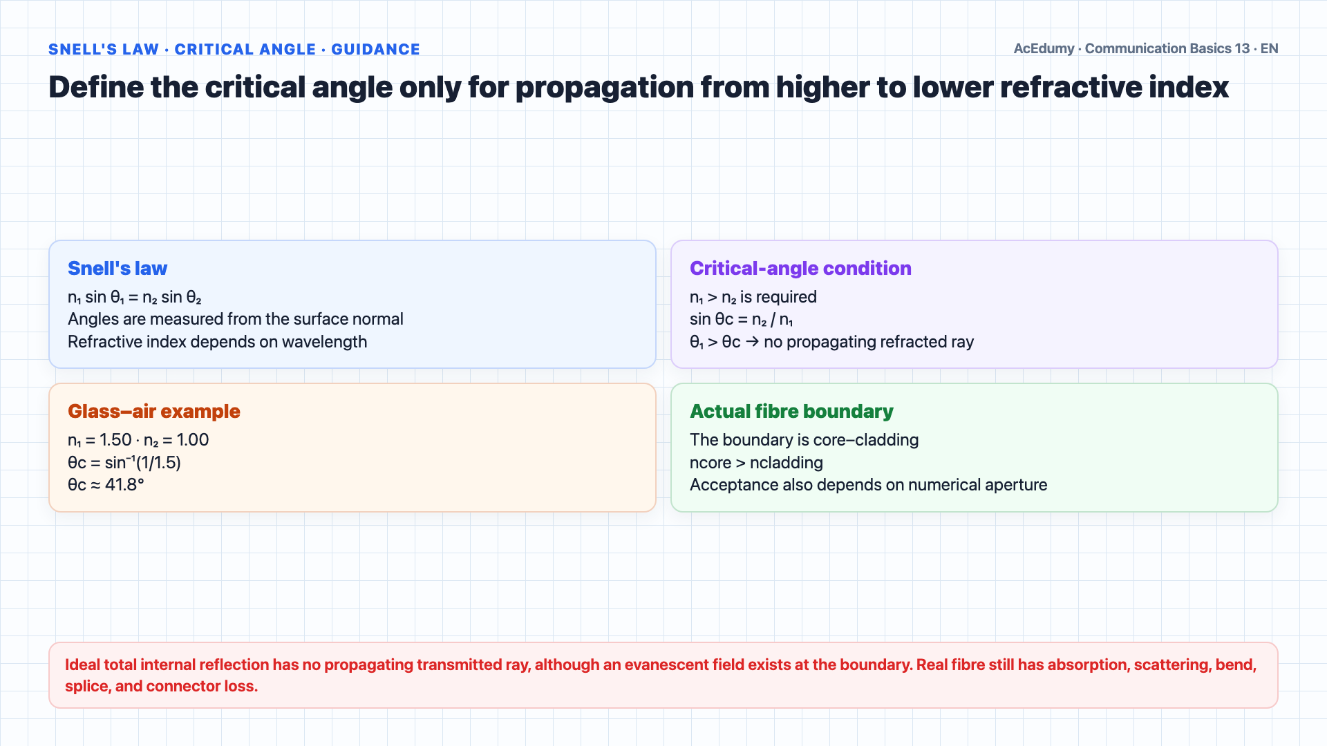
Critical angle is only the starting physics; real rate and reach follow from modal structure, dispersion, attenuation, the optical-interface standard, and the total power budget. The ray-optics model of fibre guidance begins with total internal reflection; real fibre also has wave modes, attenuation, dispersion, and bend limits.To understand this, we start with Snell's Law.When light passes from one medium to another, it changes direction based on the refractive indices of both media.Snell's Law states: n1 times sine of theta 1 equals n2 times sine of theta 2, where n1 and n2 are the refractive indices and theta 1 and theta 2 are the angles measured from the normal.There exists a special angle called the critical angle.For n₁ > n₂ and incidence above the critical angle measured from the normal, the ideal boundary has no propagating refracted ray and energy is totally reflected.No propagating power crosses the ideal boundary, although an evanescent field exists and real fibre is not lossless.This is total internal reflection; in fibre, the core–cladding index contrast and numerical aperture determine the guided modes.The critical angle is given by theta c equals arcsine of n2 divided by n1.Let us calculate an example step by step.Given: light traveling from glass with n1 equals 1.50 into air with n2 equals 1.00.Step 1: Apply the formula.Theta c equals arcsine of 1.00 divided by 1.50.Step 2: Calculate the ratio.1.00 divided by 1.50 equals 0.667.Step 3: Take the arcsine.Arcsine of 0.667 equals 41.8 degrees.This means any light hitting the glass air boundary at an angle greater than 41.8 degrees from the normal will be totally reflected back into the glass.Narration transcript
Fiber optic communication relies on a fundamental principle from physics: total internal reflection. To understand this, we start with Snell's Law. When light passes from one medium to another, it changes direction based on the refractive indices of both media. Snell's Law states: n1 times sine of theta 1 equals n2 times sine of theta 2, where n1 and n2 are the refractive indices and theta 1 and theta 2 are the angles measured from the normal. There exists a special angle called the critical angle. When light travels from a denser medium to a less dense medium, and the angle of incidence exceeds the critical angle, the light is completely reflected back. No light passes through. This is total internal reflection, and it is how fiber optics work. The critical angle is given by theta c equals arcsine of n2 divided by n1. Let us calculate an example step by step. Given: light traveling from glass with n1 equals 1.50 into air with n2 equals 1.00. Step 1: Apply the formula. Theta c equals arcsine of 1.00 divided by 1.50. Step 2: Calculate the ratio. 1.00 divided by 1.50 equals 0.667. Step 3: Take the arcsine. Arcsine of 0.667 equals 41.8 degrees. This means any light hitting the glass air boundary at an angle greater than 41.8 degrees from the normal will be totally reflected back into the glass.
2. Separate fibre structure, LED/VCSEL/laser sources, and the 850/1310/1550 nm windows
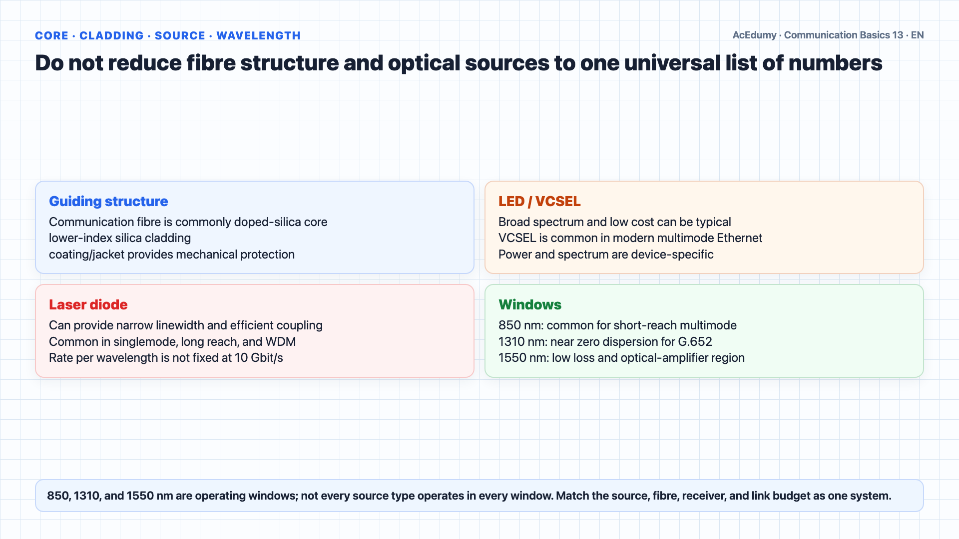
Critical angle is only the starting physics; real rate and reach follow from modal structure, dispersion, attenuation, the optical-interface standard, and the total power budget. An optical fiber consists of three concentric layers.Communication fibre commonly uses a doped-silica core; the guided optical mode occupies the core and extends into the nearby cladding.Surrounding the core is the cladding, also glass, but with a slightly lower refractive index than the core.The ncore > ncladding condition provides guidance, while absorption, scattering, bends, splices, and connectors reduce power along the link.The outer jacket provides mechanical protection.Light sources come in two types.An LED can be a low-cost broad-spectrum source; 850 nm VCSELs are also common in modern high-speed multimode Ethernet.LED power and spectral width depend on device, temperature, and operating point; 36–40 nm is not a universal limit.LEDs serve some short-reach multimode systems; high-speed multimode links commonly use VCSELs.Laser diodes can provide efficient coupling and narrow linewidth; power, beam, and linewidth are device-specific, and 1 nm is not a universal boundary.Lasers are common in singlemode long-reach and WDM systems; per-wavelength rate is not limited to 10 Gbit/s and follows the optical interface.850 nm is common for short-reach multimode; G.652 singlemode fibre is near zero chromatic dispersion around 1310 nm, while the 1550 nm region supports low loss and optical amplification; not every source operates in every window.At the receiver, a semiconductor photodiode converts light back to electrical signals.Narration transcript
An optical fiber consists of three concentric layers. The inner core is made of ultra pure glass, silicon dioxide, and this is where the light signal travels. Surrounding the core is the cladding, also glass, but with a slightly lower refractive index than the core. Because n1 of the core is greater than n2 of the cladding, total internal reflection keeps the light trapped inside the core all the way from transmitter to receiver. The outer jacket provides mechanical protection. Light sources come in two types. LEDs, Light Emitting Diodes, are common and inexpensive. They produce low power light with a wide spectral width of 36 to 40 nanometers. LEDs are used in multimode fiber for short distance, lower speed applications. Laser diodes are more expensive but produce high power, tightly focused light with a very narrow spectral width of less than 1 nanometer. Lasers are used in singlemode fiber for long haul, high speed links, including DWDM systems at 10 gigabits per second per wavelength. Both types operate at three standard wavelength windows: 850 nanometers, 1310 nanometers which is optimal for dispersion, and 1550 nanometers which has the lowest attenuation. At the receiver, a semiconductor photodiode converts light back to electrical signals.
3. Bound singlemode and multimode dimensions, dispersion, rate, and reach by standards
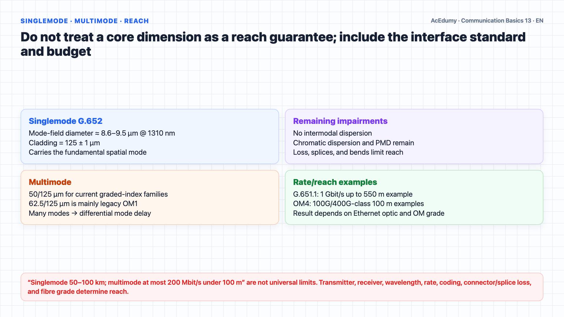
Critical angle is only the starting physics; real rate and reach follow from modal structure, dispersion, attenuation, the optical-interface standard, and the total power budget. Fibers are classified into two main types based on how light propagates.G.652 singlemode fibre has a 1310 nm mode-field diameter around 8.6–9.5 µm and 125 µm cladding; mode-field diameter is not the geometric core diameter.Below cutoff only the fundamental spatial mode propagates; it is not literally one straight geometric ray.Singlemode fibre removes intermodal dispersion; chromatic dispersion, polarization-mode dispersion, and loss still constrain rate and reach.Singlemode links may operate near 1310 or 1550 nm; reach depends on transmitter, receiver, rate, amplification, dispersion, and power budget, so 50–100 km is not universal.It is the standard for telecom backbone and submarine cables.Multimode fiber has a much larger core: 50 over 125 microns or 62.5 over 125 microns are common sizes.The larger core allows light to travel in multiple paths, or modes.This causes modal dispersion, where different modes arrive at different times, limiting both bandwidth and distance.Multimode reach depends on OM grade and Ethernet optic: G.651.1 gives a 1 Gbit/s, 550 m example, while modern OM4 interfaces include 100G/400G-class 100 m examples.Multimode comes in two sub types.Step index fiber has an abrupt change in refractive index between core and cladding, causing more dispersion.Graded index fiber gradually changes the refractive index across the core.Lower index toward the outside permits higher phase velocity and reduces differential mode delay; modes need not arrive at exactly the same time.Graded index significantly reduces modal dispersion.Narration transcript
Fibers are classified into two main types based on how light propagates. Singlemode fiber has a very small core diameter of just 9 microns, with a cladding diameter of 125 microns. Because the core is so small, light travels in a single straight path. This eliminates a problem called modal dispersion, allowing very high bandwidth over very long distances. Singlemode fiber operates at 1310 or 1550 nanometers with laser diodes, and can span 50 to 100 kilometers between repeaters. It is the standard for telecom backbone and submarine cables. Multimode fiber has a much larger core: 50 over 125 microns or 62.5 over 125 microns are common sizes. The larger core allows light to travel in multiple paths, or modes. This causes modal dispersion, where different modes arrive at different times, limiting both bandwidth and distance. Multimode supports up to 200 megabits per second over distances under 100 meters, making it suitable for LAN applications within buildings. Multimode comes in two sub types. Step index fiber has an abrupt change in refractive index between core and cladding, causing more dispersion. Graded index fiber gradually changes the refractive index across the core. Light in the outer layers travels faster, compensating for the longer path, so all modes arrive at roughly the same time. Graded index significantly reduces modal dispersion.
4. Summarize fibre selection through guidance, dispersion, power-budget, and interface gates
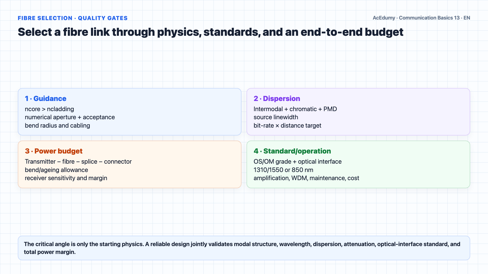
Critical angle is only the starting physics; real rate and reach follow from modal structure, dispersion, attenuation, the optical-interface standard, and the total power budget. Let us review.Snell's Law governs how light bends at boundaries between materials.When the angle exceeds the critical angle, total internal reflection occurs, which is the principle behind fiber optics.Optical fiber consists of a glass core with higher refractive index surrounded by glass cladding with lower refractive index, keeping light trapped in the core.LEDs serve some short multimode systems; modern high-speed multimode Ethernet commonly uses VCSELs.Laser diodes serve singlemode long reach and high-speed multimode VCSEL interfaces; the standard determines the pairing.Common windows are 850, 1310, and 1550 nm; minima depend on fibre type, with G.652 near zero dispersion at 1310 nm and low loss in the 1550 nm region.Singlemode G.652: about 9 µm mode field / 125 µm cladding and the fundamental mode; system budget determines reach and bandwidth.Multimode: current graded-index families use 50/125 µm; 62.5/125 µm is mainly legacy OM1; OM grade and optical interface determine reach.Graded index reduces modal dispersion compared to step index.In the next lesson, we will cover fiber types in more detail, Free Space Optics, and a complete comparison of all transmission media.Narration transcript
Let us review. Snell's Law governs how light bends at boundaries between materials. When the angle exceeds the critical angle, total internal reflection occurs, which is the principle behind fiber optics. Optical fiber consists of a glass core with higher refractive index surrounded by glass cladding with lower refractive index, keeping light trapped in the core. LEDs are used with multimode fiber for short, lower speed links. Laser diodes are used with singlemode fiber for long haul, high speed links. Three wavelength windows: 850 nanometers, 1310 nanometers for minimum dispersion, and 1550 nanometers for minimum attenuation. Singlemode: 9 over 125 micron core, single path, long distance, high bandwidth. Multimode: 50 or 62.5 over 125 micron core, multiple paths, LAN distances. Graded index reduces modal dispersion compared to step index. In the next lesson, we will cover fiber types in more detail, Free Space Optics, and a complete comparison of all transmission media.
Source video: Communication Basics #13 — Fiber Optics Fundamentals (6:53)