Communication Basics · Fiber Types, FSO, and Transmission-Media Selection
#14 Singlemode and multimode fibre, index profiles, tight-buffer and loose-tube cable, free-space optical link budgets, standards-based transmission-media comparison
Compare fibre, FSO, copper, coax, and RF through interface standards, link budgets, availability, and lifecycle—not a fixed-number table.
Question
Compare singlemode and multimode fibre through mode field, dispersion, and interface standards; separate step/graded index from cable construction; build an FSO geometric and atmospheric link budget; select copper, coax, microwave, satellite, and fibre through specific standards and operational requirements rather than fixed rate, BER, and security claims.
Written solution and narration transcript(shows the full solution)
Below are all the lines written in the notebook together with the full narration transcript.
1. Bound singlemode and multimode claims by mode field, dispersion, and interface standards
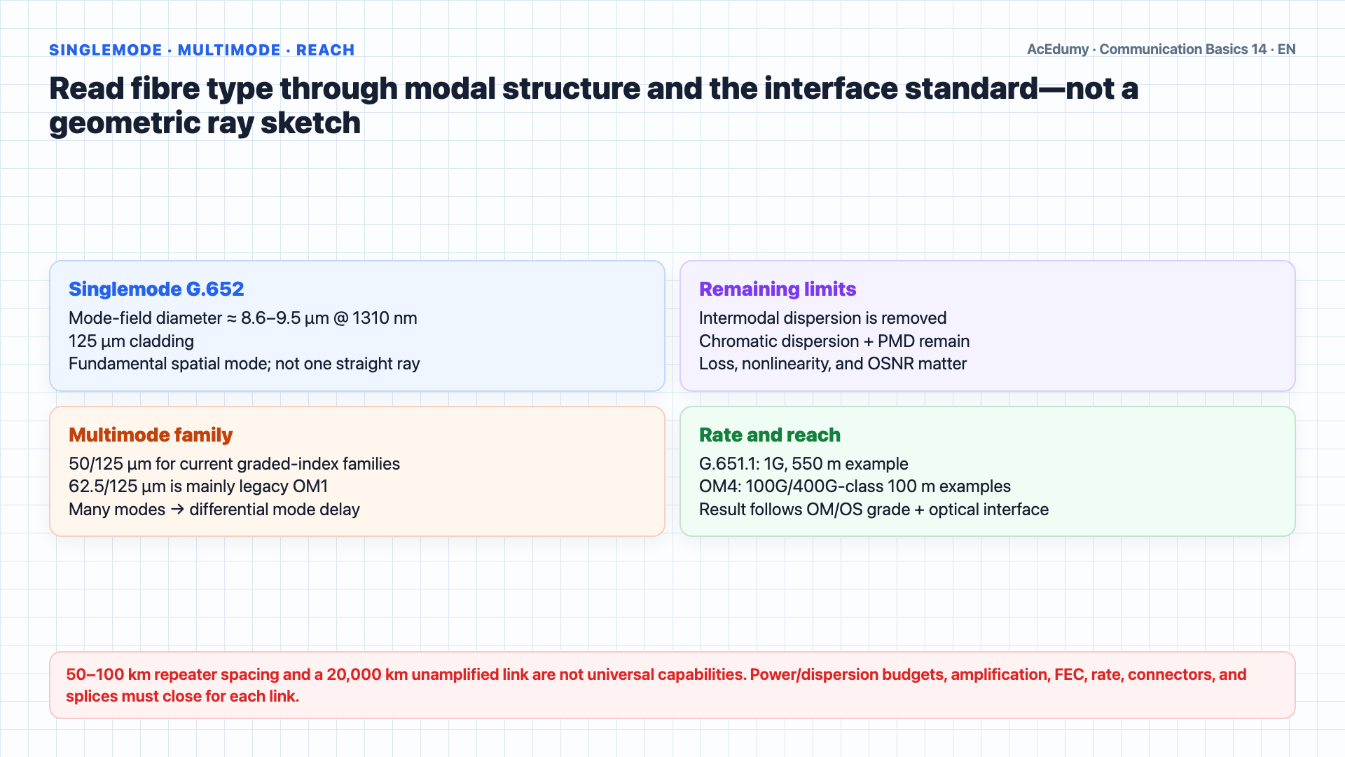
Rate, reach, BER, security, and cost are not immutable properties of a medium; verify them for the specific interface, link budget, site, and operation. Welcome back.In the previous lesson we covered the fundamentals of fiber optics: Snell's Law, total internal reflection, fiber structure, and light sources.Today we go deeper into fiber types and then explore an exciting wireless technology called Free Space Optics.We will finish with a complete comparison of all transmission media.Let us start with a closer look at singlemode versus multimode fiber.G.652 singlemode fibre has a mode-field diameter around 8.6–9.5 µm at 1310 nm and 125 µm cladding; mode field is not geometric core diameter.Below cutoff the fundamental spatial mode propagates; it is not one straight ray. Intermodal dispersion is removed, while chromatic dispersion and PMD remain.This gives singlemode fiber extremely high bandwidth.Reach follows power/dispersion budgets, rate, FEC, amplification, and OSNR; 50–100 km and a 20,000 km unamplified reach are not universal.G.652 fibre is near zero chromatic dispersion around 1310 nm and has low loss in the 1550 nm region; exact values depend on fibre grade.Singlemode is the backbone of modern telecommunications and submarine cables.Current graded-index multimode families commonly use 50/125 µm; 62.5/125 µm is mainly found in legacy OM1 plants.Multimode fibre carries multiple spatial modes; interpreting modes only as geometric zig-zag rays is incomplete.This causes modal dispersion, where different modes arrive at different times.Multimode reach depends on OM grade and optic: G.651.1 gives a 1 Gbit/s, 550 m example, while OM4 interfaces include 100G/400G-class 100 m examples.Narration transcript
Welcome back. In the previous lesson we covered the fundamentals of fiber optics: Snell's Law, total internal reflection, fiber structure, and light sources. Today we go deeper into fiber types and then explore an exciting wireless technology called Free Space Optics. We will finish with a complete comparison of all transmission media. Let us start with a closer look at singlemode versus multimode fiber. Singlemode fiber has a tiny core of just 9 microns. Light travels in a single straight path, which means zero modal dispersion. This gives singlemode fiber extremely high bandwidth. Repeater spacing is 50 to 100 kilometers, and some systems achieve repeaterless links over 20000 kilometers. The wavelength of 1310 nanometers gives minimum dispersion, while 1550 nanometers gives minimum attenuation. Singlemode is the backbone of modern telecommunications and submarine cables. Multimode fiber has a much larger core: 50 over 125 or 62.5 over 125 microns. Light bounces through the core in multiple paths, called modes. This causes modal dispersion, where different modes arrive at different times. Multimode supports up to 200 megabits per second over distances under 100 meters, making it ideal for local area networks within buildings.
2. Separate step/graded-index behaviour from tight-buffer and loose-tube cable construction
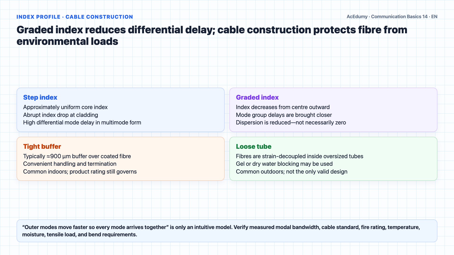
Rate, reach, BER, security, and cost are not immutable properties of a medium; verify them for the specific interface, link budget, site, and operation. Multimode fiber comes in two important varieties: step index and graded index.In step index fiber, there is an abrupt change in refractive index between the core and the cladding.Each mode, or ray of light, takes a different path through the core.Rays bouncing at steep angles travel longer distances than rays near the center.The result?Different modes arrive at the receiver at different times.This pulse spreading is called modal dispersion, and it limits both bandwidth and distance.A graded-index profile reduces differential mode delay; it does not make modal dispersion zero in every case.The index decreases from centre outward in a near-continuous or controlled profile; physically separate glass layers are not required.The graded-index profile is designed to balance modal group delays; comparing only ray length and one velocity is incomplete.Field distribution across the centre and outer regions jointly sets modal group delay; geometric path length alone is insufficient.Mode group delays are brought closer; exact simultaneous arrival of every mode is not guaranteed.Graded index dramatically reduces modal dispersion.Now, fiber cables also come in different physical constructions.Tight-buffer cable typically applies an approximately 900 µm buffer over coated fibre; indoor suitability also depends on fire, tensile, bend, and temperature ratings.Loose-tube cable strain-decouples fibres inside an oversized tube; water blocking may use gel or dry materials.Loose tube is common outdoors, but the site and cable standard govern; it is not the only valid outdoor construction.Narration transcript
Multimode fiber comes in two important varieties: step index and graded index. In step index fiber, there is an abrupt change in refractive index between the core and the cladding. Each mode, or ray of light, takes a different path through the core. Rays bouncing at steep angles travel longer distances than rays near the center. The result? Different modes arrive at the receiver at different times. This pulse spreading is called modal dispersion, and it limits both bandwidth and distance. Graded index fiber solves this elegantly. Instead of an abrupt change, many layers of glass are applied, each with a slightly lower refractive index as you move outward from the center. Light rays in the outer layers travel through lower-index glass, so they move faster. Light rays near the center travel slower but take a shorter path. The result is that all modes arrive at the receiver at approximately the same time. Graded index dramatically reduces modal dispersion. Now, fiber cables also come in different physical constructions. Tight buffer cables wrap a 900 micron coating directly around each fiber, making them flexible and easy to handle for indoor installations. Loose tube cables place the fiber inside a larger tube filled with gel, which protects against moisture and temperature changes. Loose tube is preferred for outdoor and underground installations.
3. Build an FSO link budget with geometric loss, atmosphere, pointing, and fade margin
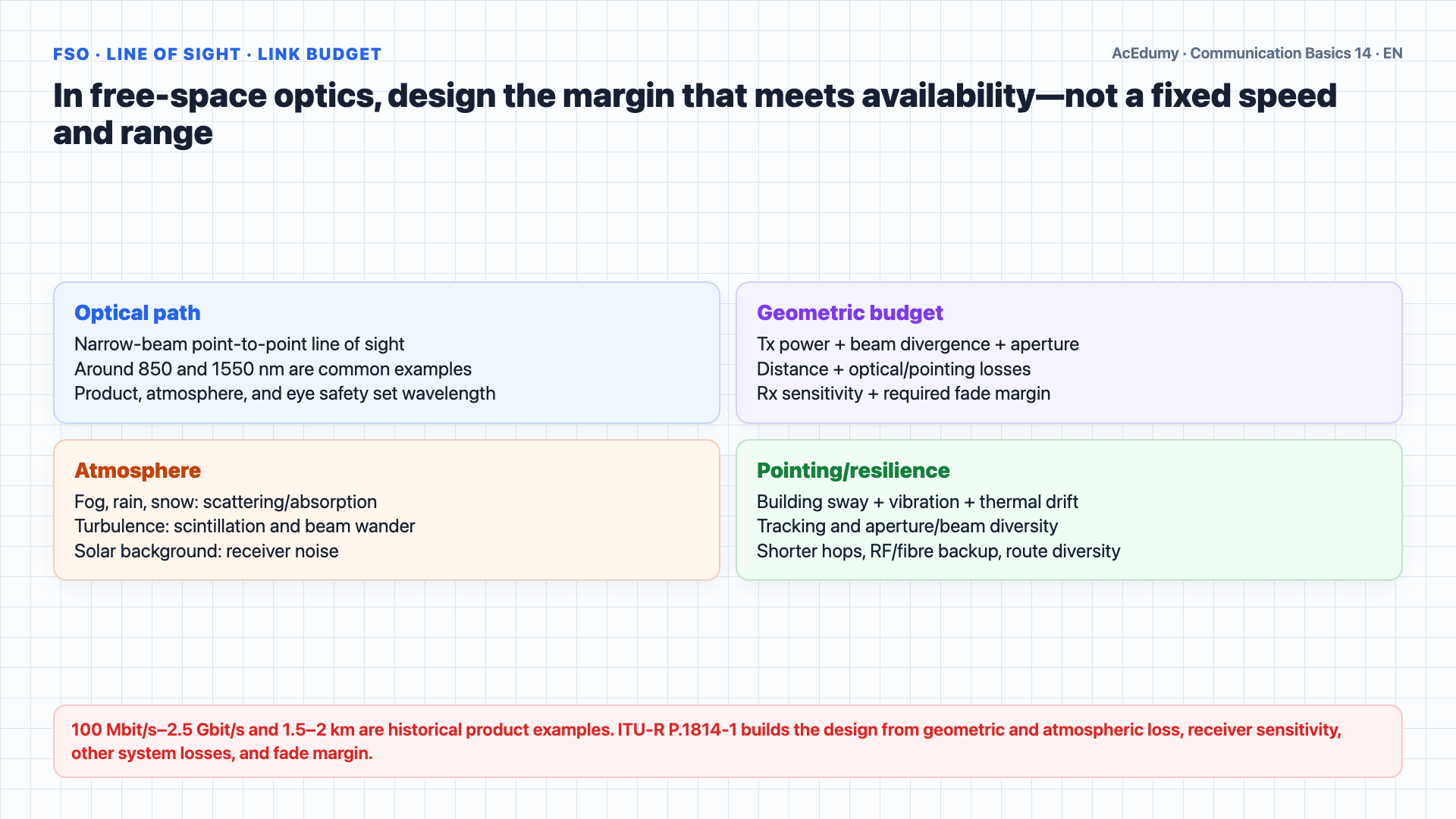
Rate, reach, BER, security, and cost are not immutable properties of a medium; verify them for the specific interface, link budget, site, and operation. Now let us explore Free Space Optics, or FSO.FSO is wireless optical transmission through the atmosphere, using infrared light instead of radio waves.Old building-proximity percentages are not current or universal design inputs; survey the candidate FSO path directly.FSO can serve access, campus, or backup links when line of sight and the target availability can be met.An FSO transmitter uses an optical source and beam shaping, while the receiver uses an aperture and photodetector; eye-safety rules limit emitted power.Around 850 and 1550 nm are common product examples; device, atmospheric window, receiver, and eye safety set the wavelength.FSO rate, duplex, and reach are not fixed; they follow the product interface, geometric/atmospheric budget, and target availability.Line of sight is required, just like microwave.However, FSO faces several atmospheric challenges.Fog is the biggest enemy.Fog loss is modelled from visibility, droplet distribution, and wavelength-dependent Mie scattering/absorption—not one universal droplet diameter.Scintillation occurs when heated air creates temperature variations, causing the signal to dance and fluctuate at the receiver.Molecular absorption is one atmospheric-loss component; clear air, hydrometeors, and wavelength must be modelled together.Building sway from wind or seismic activity can misalign the transmitter and receiver.Mitigation may include shorter hops, aperture/beam diversity, automatic tracking, adequate fade margin, and RF/fibre backup.Narration transcript
Now let us explore Free Space Optics, or FSO. FSO is wireless optical transmission through the atmosphere, using infrared light instead of radio waves. In the United States, only 5 percent of buildings are connected to fiber, but 75 percent are within one mile of the fiber backbone. FSO bridges this last mile gap. Each FSO unit uses a high power laser and a lens to transmit light through the air to a receiving lens on another building. It operates at wavelengths around 800 and 1550 nanometers. FSO offers impressive capabilities: 100 megabits per second up to 2.5 gigabits per second, full duplex communication, over distances of 1.5 to 2 kilometers. Line of sight is required, just like microwave. However, FSO faces several atmospheric challenges. Fog is the biggest enemy. Fog droplets are only a few hundred microns in diameter, close to the wavelength of the light, causing severe scattering and absorption. Scintillation occurs when heated air creates temperature variations, causing the signal to dance and fluctuate at the receiver. Absorption happens when water molecules in the atmosphere convert light energy into heat. Building sway from wind or seismic activity can misalign the transmitter and receiver. Solutions include multi-beam systems, divergent beams, and shorter link distances.
4. Compare media through specific interfaces and sites instead of a fixed rate/BER table
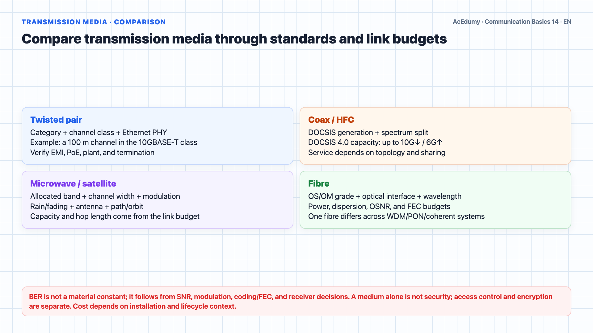
Rate, reach, BER, security, and cost are not immutable properties of a medium; verify them for the specific interface, link budget, site, and operation. Media can be compared only for a specific interface standard, topology, and site; a medium name is not a performance row.Usable twisted-pair spectrum and rate follow category, channel class, and Ethernet PHY; for example, the 10GBASE-T class targets a suitable 100 m channel.BER is not a medium constant; it follows SNR, modulation, FEC, and receiver decisions.Copper channel length and active-device spacing come from the cabling and PHY standard.Security follows access control and encryption; cost follows plant, energy, and lifecycle context.Coax/HFC spectrum follows the DOCSIS generation and operator plan; DOCSIS 4.0 specifies capacity up to 10 Gbit/s down and 6 Gbit/s up.HFC node/amplifier spacing follows cable loss, spectrum, tilt, power, and site topology.A physical medium alone is not security; authentication, access control, and encryption are required.Cost depends on installation, active equipment, energy, maintenance, and scale.Fixed microwave uses allocated bands, channel widths, modulation, and radio standards; capacity and errors follow bandwidth, SNR, polarization, and FEC.Hop length follows line of sight, Fresnel clearance, antennas, rain/fading, and the availability budget.Even a narrow beam is not a security guarantee; physical and cryptographic controls are separate.Cost depends on installation, active equipment, energy, maintenance, and scale.Satellite bands follow service, region, and licence; capacity follows beam/transponder bandwidth, modulation, FEC, and load sharing.Orbit altitude is geometry, not coverage distance; reach, latency, security, and cost follow constellation and service design.Fibre is a strong candidate for many high-capacity long-reach links, but is not the automatic winner at every site.A fibre system uses a defined optical band and interface; capacity follows wavelengths, symbol rate, spectral efficiency, OSNR, and nonlinear limits.Optical BER follows received OSNR/power, modulation, DSP, and FEC; it is not a fibre-material constant.Optical reach follows power, dispersion, OSNR, amplifier/regenerator placement, and system margin.Fibre is not tap-proof; security and lifecycle cost are designed separately.For our practical examples: A link between Turkey and Germany?Subsea/terrestrial fibre and satellite provide different latency, capacity, and resilience roles.For an Ankara–Istanbul backbone, define capacity and protection targets.Fibre is a strong candidate; route, optical system, and protection architecture still require selection.For an office LAN, measure rate, PoE, existing plant, and client interfaces.Twisted pair, fibre, and wireless access may be combined according to requirements.For a mountain route, inspect profile, line of sight, climate, licence, and access points.Microwave is one candidate; compare its link budget with fibre and satellite options.For cable TV/HFC, identify the existing plant and DOCSIS/video architecture.Coax may serve the final segment; modern networks are generally HFC with deeper fibre deployment.Narration transcript
Let us now compare all five major transmission media side by side. Twisted pair operates from 1 megahertz to 1 gigahertz, with bit rates from 2 megabits per second up to 1 gigabit per second. Its bit error rate is 10 to the minus 5. Repeater distance is just 2 kilometers to 100 meters. Security is poor, and cost is low. Coaxial cable operates at 1 gigahertz, reaching 565 megabits per second with a BER of 10 to the minus 7 to minus 9. Repeaters every 2 to 3 kilometers. Good security. Moderate cost. Microwave covers 300 megahertz to 40 gigahertz, up to 622 megabits per second with a BER of 10 to the minus 9. Repeaters at 30 to 70 kilometer intervals. Poor security. Moderate cost. Satellite uses 390 megahertz to 30 gigahertz, reaching 155 megabits per second with a BER of 10 to the minus 9. Coverage from 800 to 36000 kilometers, but poor security and high cost. Fiber optic is the champion. Operating from 750 terahertz to 194 terahertz, with bit rates from 2.5 to 10 gigabits per second and potential for 150 terabits per second. BER of 10 to the minus 11 to minus 13. Repeaters at 50 to 100 kilometers, extendable to 6000 kilometers. Good security and moderate to high cost. For our practical examples: A link between Turkey and Germany? Satellite or undersea fiber. Ankara to Istanbul backbone? Fiber. Office LAN? Twisted pair. Erzurum to Trabzon across mountains? Microwave. Cable TV distribution? Coaxial.
5. Summarize selection through requirement, standard, budget, and operation quality gates
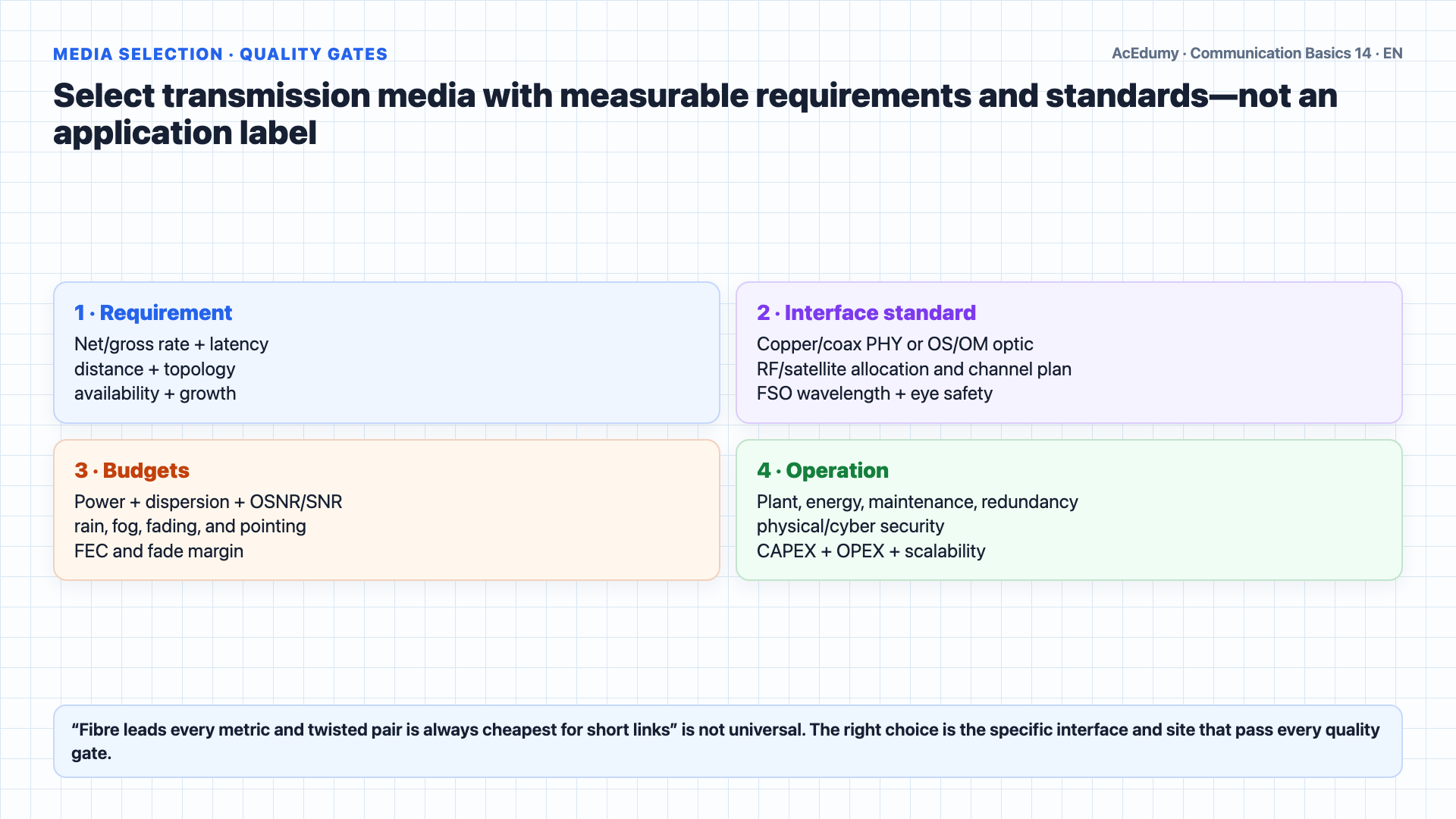
Rate, reach, BER, security, and cost are not immutable properties of a medium; verify them for the specific interface, link budget, site, and operation. Let us summarize today's lesson.Singlemode G.652 may use about a 9 µm mode field, 125 µm cladding, and a laser interface; system budget sets reach.Multimode includes current 50/125 µm and legacy 62.5/125 µm families; LED/VCSEL, rate, and reach follow the optical standard.Step index causes more dispersion due to abrupt refractive index change.A graded-index profile reduces differential mode delay; verify performance through measured modal bandwidth.Tight buffer is common indoors and loose tube outdoors; the product standard and site loads govern the actual choice.FSO can be an access or backup route; atmosphere, pointing, eye safety, and target availability must close in the link budget.Fibre is strong for high capacity and reach, while twisted pair can be economical at short reach; BER and lifecycle cost still depend on the selected system and site.The right choice depends on the application: distance, bandwidth, environment, and budget.In the next lesson, we will explore circuit switching, packet switching, and the structure of the public telephone network.Narration transcript
Let us summarize today's lesson. Singlemode fiber: 9 over 125 micron core, laser source, 50 to 100 kilometer range, ideal for telecom backbone. Multimode fiber: 50 or 62.5 over 125 micron core, LED source, under 100 meters, used for LANs. Step index causes more dispersion due to abrupt refractive index change. Graded index reduces dispersion by gradually varying the refractive index. Tight buffer cables for indoor, loose tube cables for outdoor installations. Free Space Optics bridges the last mile with laser links through the atmosphere, but faces challenges from fog, scintillation, and absorption. Among all transmission media, fiber optic leads in bandwidth, bit error rate, and distance, while twisted pair remains the most economical for short distances. The right choice depends on the application: distance, bandwidth, environment, and budget. In the next lesson, we will explore circuit switching, packet switching, and the structure of the public telephone network.
Source video: Communication Basics #14 — Fiber Types, FSO & Media Comparison (8:45)