Electronics 1 · Electronics Basics
#04 Full-wave rectifiers — bridge and center-tapped topologies
Trace both half-cycles, derive the ideal average output, include silicon diode losses correctly, and compare bridge and center-tapped implementations.
Question
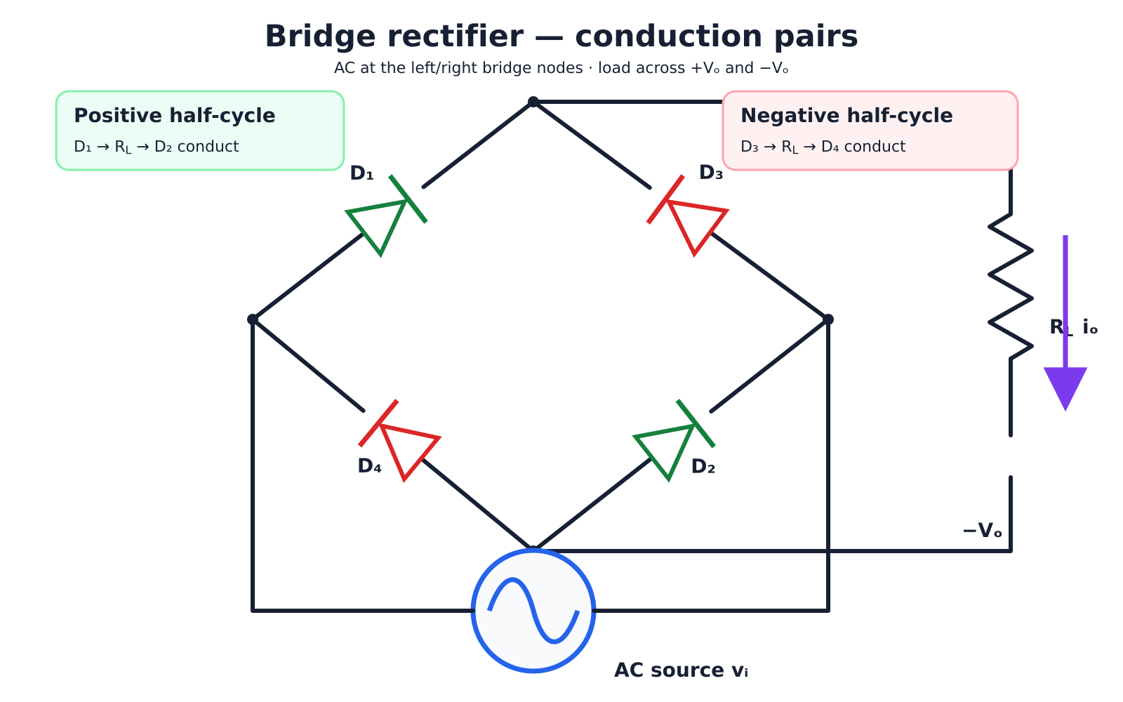
A sinusoidal source is to be converted into full-wave pulsating DC. Explain the conduction paths in a four-diode bridge and in a two-diode center-tapped rectifier. Derive the ideal average V_{DC}. For a silicon bridge with V_m = 10 V and V_F = 0.7 V per diode, distinguish the quick peak-shift estimate from the exact constant-drop result, then compare the two topologies.
Written solution and narration transcript(shows the full solution)
Below are all the lines written in the notebook together with the full narration transcript.
1. Why full-wave rectification?
Last lesson: half-wave rectifierHalf-wave ideal:Half-wave discards one half of every cycleFull-wave uses both half-cyclesFull-wave ideal:Implementations: 4-diode bridge or 2-diode center tapNarration transcript
Welcome back. In the last lesson we built the half-wave rectifier — one diode, one resistor, and we got V_DC equals zero point three one eight times V_m. But we threw away half of every cycle. The negative humps were chopped to zero, wasted. Today we fix that. We are going to use both halves of the sine wave. Same V_m at the input, but the DC component will be exactly twice as big — V_DC equals zero point six three six times V_m. We will see two ways to do it. First, the bridge rectifier: four diodes arranged in a clever diamond shape. Second, the center-tapped transformer rectifier: only two diodes, but the transformer does some of the work for us. Let us start with the bridge.
2. Bridge conduction paths
Correct bridge pairing: D1–D2 for one source polarity and D3–D4 for the opposite polarity. AC input: left and right bridge nodesLoad RL: +Vo and −Vo nodesPositive half-cycle: D1 and D2 ONPath: source → D1 → RL → D2 → sourceNegative half-cycle: D3 and D4 ONPath: source → D3 → RL → D4 → sourceBoth paths force io through RL in the same directionNarration transcript
Here is the bridge rectifier. Four diodes — D one, D two, D three, D four — arranged in a diamond. The AC source connects to the left and right corners, and the load resistor sits across the top and bottom corners. The trick is in how the diodes are oriented. On the positive half cycle, the top of the AC source is positive. Current can flow forward through D one, then through the resistor from top to bottom, then back through D two to the negative side. D three and D four are reverse biased — they stay off. On the negative half cycle, the polarity flips. Now D three and D four turn on, and current flows through D three, then through the resistor in the same direction as before — top to bottom — then back through D four. D one and D two are now off. Notice this: no matter which half cycle the source is in, the current through the resistor always flows the same direction. That is the magic of the bridge.
3. Bridge output and diode losses
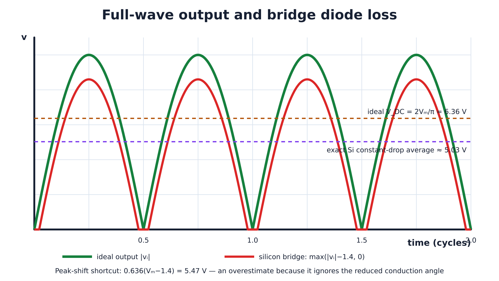
The common 5.47 V peak-shift shortcut ignores the narrower conduction interval; the exact 0.7 V constant-drop integral gives about 5.03 V. Ideal bridge:Bridge path: two silicon diodes → VDΣ = 1.4 VQuick estimate:Narration transcript
Now examine the bridge output carefully. With ideal diodes, every negative half-cycle is folded upward, so v_o equals the magnitude of v_i. Averaging that waveform over a full period gives two V_m divided by pi, or about zero point six three six V_m. For a ten-volt peak, the ideal average is six point three six volts. With silicon diodes, two devices conduct in series on every half-cycle, so the path drop is about one point four volts. A common quick estimate is zero point six three six times V_m minus one point four. At ten volts, that gives five point four seven volts. But that shortcut also assumes a full half-cycle of conduction, so it overestimates the average. For the constant-drop model, define alpha as sine inverse of one point four divided by V_m. The exact average is the quantity two V_m cosine alpha minus one point four times pi minus two alpha, all divided by pi. At ten volts, the result is about five point zero three volts. So use five point four seven only as a quick peak-shift estimate, and five point zero three as the more accurate constant-drop result.
4. Center-tapped rectifier
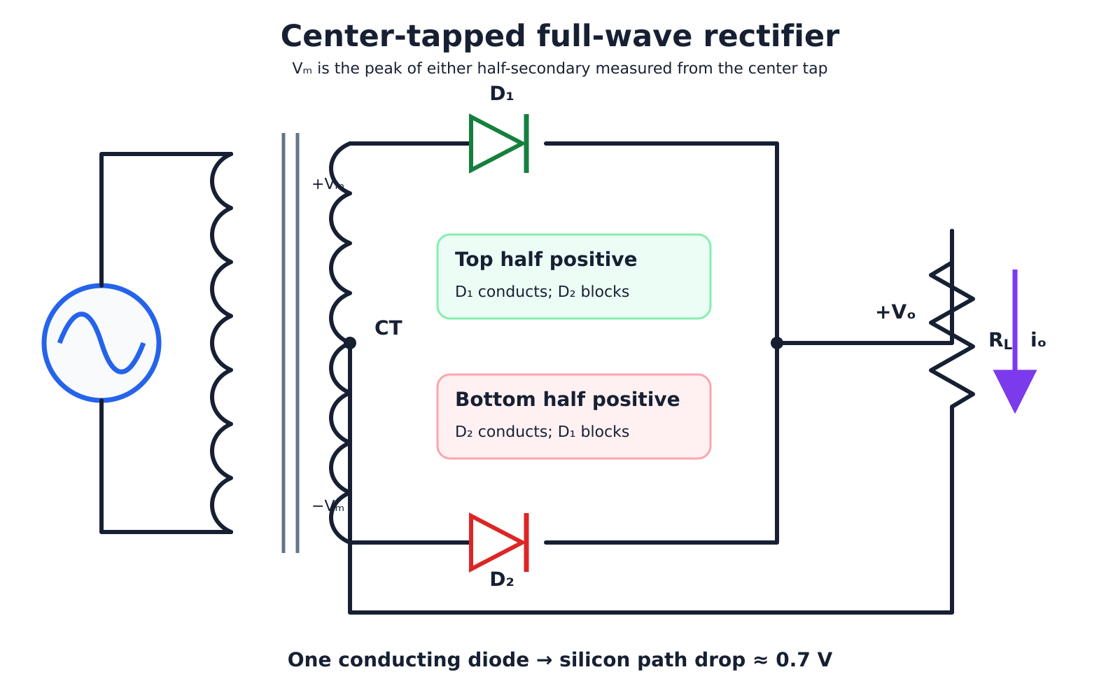
Here V_m is the peak voltage from either end of the secondary to the center tap, not the end-to-end secondary peak. Secondary: two equal half-windings + center tap (CT)Reference: CT = 0 VDefine Vm as each half-secondary peak relative to CTTop half positive → D1 ON, D2 OFFBottom half positive → D2 ON, D1 OFFIdeal:Only one silicon diode conducts → path drop ≈ 0.7 VNarration transcript
Now consider the second topology: the center-tapped transformer rectifier. It achieves full-wave rectification with two diodes, but it requires a transformer secondary split into two equal half-windings. Their common midpoint is the center tap, and we use it as the zero-volt reference. Define V_m carefully here: it is the peak voltage from either end of the secondary to the center tap. The peak measured end to end across the whole secondary is therefore two V_m. When the top half-winding is positive, D one conducts through the load and D two blocks. On the next half-cycle the bottom half-winding becomes positive, D two conducts, and D one blocks. Current through the load keeps the same direction. For ideal diodes, the output is full-wave rectified and its average is two V_m divided by pi, or about zero point six three six V_m, using that half-secondary definition. Only one silicon diode is in each conducting path, so the path drop is about zero point seven volts rather than one point four.
5. Bridge versus center tap
Bridge rectifier4 diodes; 2 conduct each half-cycleUses the full secondary on both half-cycles; better transformer utilizationCenter-tapped rectifier2 diodes; 1 conducts each half-cycleRequires a split secondary; each half is used alternatelyCompare VDC only after defining Vm at the same terminalsModern default: bridge — diodes are cheap, transformer utilization is betterNarration transcript
Which topology should you choose? A bridge uses four diodes, with two conducting on each half-cycle, so its silicon path loses about one point four volts. In return, it needs only an ordinary two-terminal secondary and uses the full secondary winding on both half-cycles. That gives good transformer utilization. A center-tapped rectifier uses two diodes and only one diode drop per path. However, it needs a special split secondary, and only one half-winding supplies the load on each half-cycle. The nonconducting diode also sees a larger peak inverse voltage, approximately two V_m when V_m is defined from one end to the center tap. Be careful when comparing formulas: zero point six three six V_m applies to both ideal full-wave outputs only after V_m has been defined at the actual conducting input terminals. Do not compare a bridge end-to-end peak with a center-tapped half-secondary peak as though they were the same voltage. In most modern supplies, the bridge is preferred because diodes are inexpensive and transformer utilization matters. Center-tapped designs remain useful when saving one diode drop is especially important.
6. Summary and smoothing
Full-wave: both half-cycles become positive load pulsesIdeal average:Bridge: 4 diodes, 2 drops per conducting pathCenter tap: 2 diodes, 1 drop per conducting pathOutput is still pulsating DC at twice the input frequencyNext stage: capacitor filtering reduces rippleNarration transcript
Let us recap. Full-wave rectification uses both halves of every sine cycle — no waste. V_DC equals zero point six three six times V_m, exactly twice the half-wave value. Two ways to build it: the bridge rectifier with four diodes, and the center-tapped transformer with two diodes. Bridge: simpler transformer but two diode drops per half cycle. Center-tapped: only one diode drop per half cycle, but a more expensive transformer. Even with full-wave rectification, the output is still pulsating DC — humps separated by zeros at every half-cycle boundary. Real power supplies smooth this out by adding a capacitor across the load, which charges up to the peak and holds it during the dips. That is the next piece of the puzzle, and we will get there in due course. See you in the next lesson.
Source video: Electronics Basics #04 | Full-Wave Rectifier: Bridge + Center-Tapped, V_DC = 0.636 V_m (7:00)