Electronics 1 · Electronics Basics
#03 Half-wave rectifier — ideal and silicon diode models
Follow each half-cycle, sketch the pulsating output, and compare the average DC value for ideal and silicon diodes.
Question
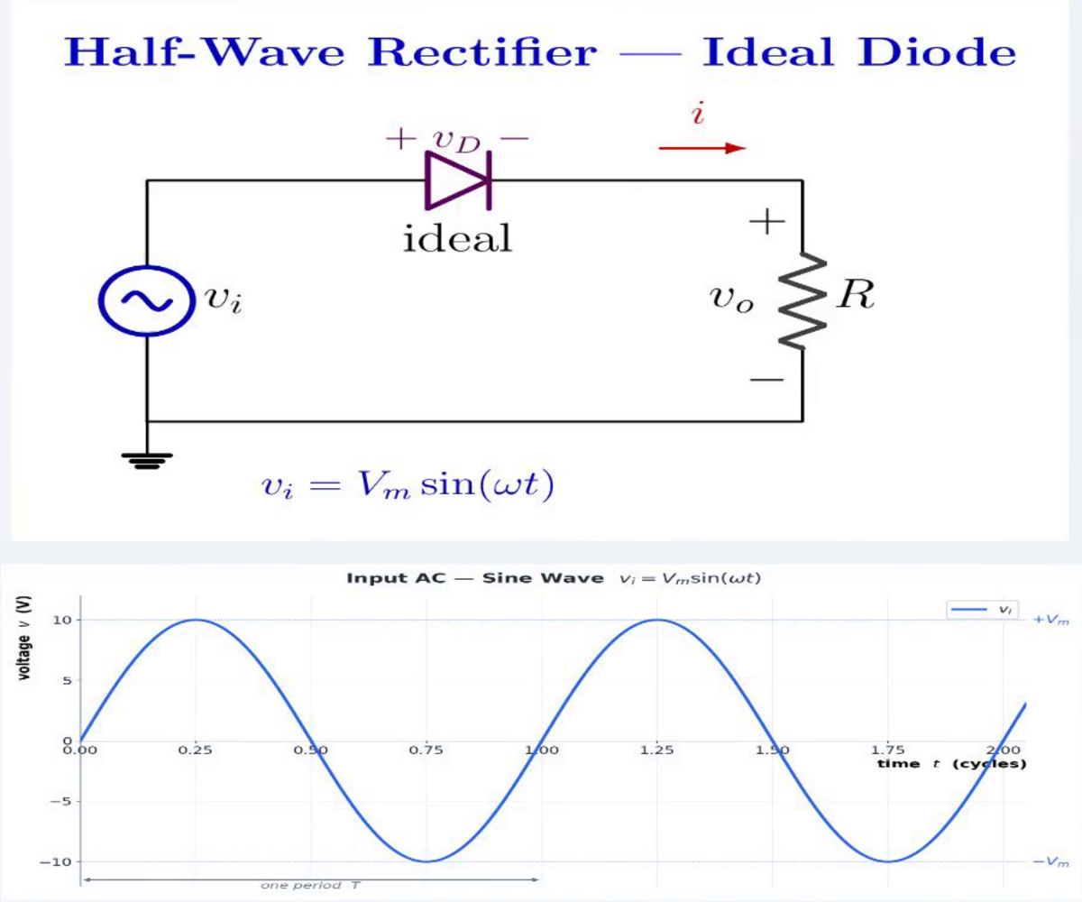
A sinusoidal source v_i = V_m sin(ωt) drives a series diode and load resistor R. Determine v_o(t) and derive V_{DC} for an ideal diode. Then use the 0.7 V constant-drop silicon model to state the conduction condition, estimate V_{DC}, and compare both models when V_m = 10 V.
Written solution and narration transcript(shows the full solution)
Below are all the lines written in the notebook together with the full narration transcript.
1. Why rectification?
Wall outlet: AC sine wave, ±VmFrequency: 50 Hz or 60 HzMost electronic circuits need DCRectification: AC → DCHalf-wave rectifier: one diode + one load resistor + one AC sourceNarration transcript
Welcome back. So far, we have used DC sources in every example: a battery sitting at a fixed voltage. But the wall outlet in your house gives you AC: alternating current. A sine wave that swings positive and negative, sixty times per second in some countries, fifty in others. Almost every piece of electronics — your phone charger, your laptop, your TV — needs DC inside to run. So somewhere in those devices, AC has to be converted into DC. That conversion process is called rectification, and the simplest version is what we cover today: the half-wave rectifier. Just one diode, one resistor, and an AC source. Let us see how it works.
2. Ideal circuit and input
The diode orientation lets the positive half-cycle drive the load and blocks the opposite half-cycle. Circuit: AC source + ideal diode + load resistor RIdeal diode:Positive half-cycle: vi rises to +VmNegative half-cycle: vi falls to −VmGoal: let one half-cycle reach the loadNarration transcript
Here is the circuit. An AC voltage source on the left, a diode in series, and a load resistor on the right. We will start with an ideal diode — zero forward drop, perfect switch. The input voltage is a sine wave: v_i equals V_m times sine omega t, where V_m is the peak amplitude. On the positive half cycle, the input swings up to plus V_m. On the negative half cycle, it swings down to minus V_m. The diode is going to slice this sine wave in half. Let us see how.
3. Ideal operation and average
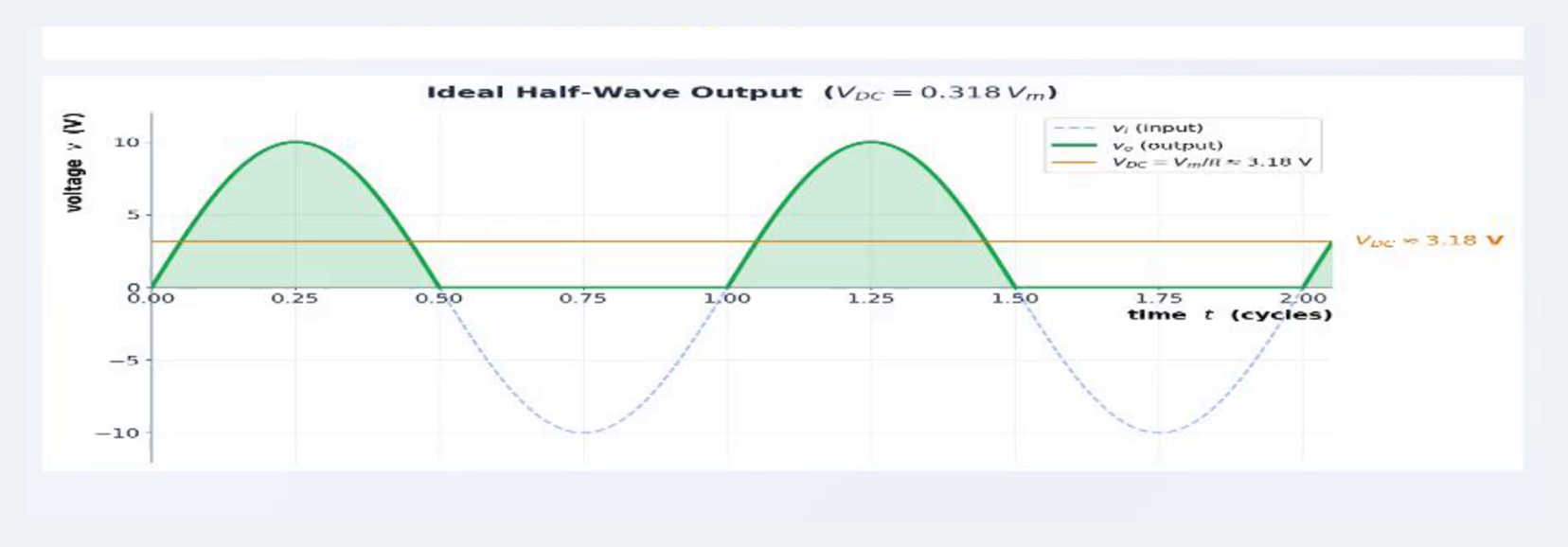
The ideal output follows the positive input and remains zero throughout each negative half-cycle. Positive half-cycle → forward bias → diode ONON ideal diode → short circuitNegative half-cycle → reverse bias → diode OFFNarration transcript
Look at the diode polarity in this circuit. The anode is connected to the AC source side, and the cathode connects to the resistor and back to the source. When the source goes positive, the anode is positive. Forward bias. The ideal diode turns on, acts like a short circuit, and the entire input voltage drops across the resistor. v_o equals v_i. When the source swings negative, the anode is negative. Reverse bias. The diode turns off, acts like an open circuit, and the resistor sees nothing. v_o equals zero. So the output is the input, but with all the negative humps chopped off. Just positive bumps with flat zeros in between. This is half-wave rectified. Now, what is the average value of this signal? If you integrate one positive hump over a full period and divide by the period, you get one over pi times V_m. And one over pi is approximately zero point three one eight. So V_DC equals zero point three one eight times V_m. That is the DC component the load resistor sees on average. Memorize this number. It comes up everywhere in rectifier design.
4. Silicon diode model
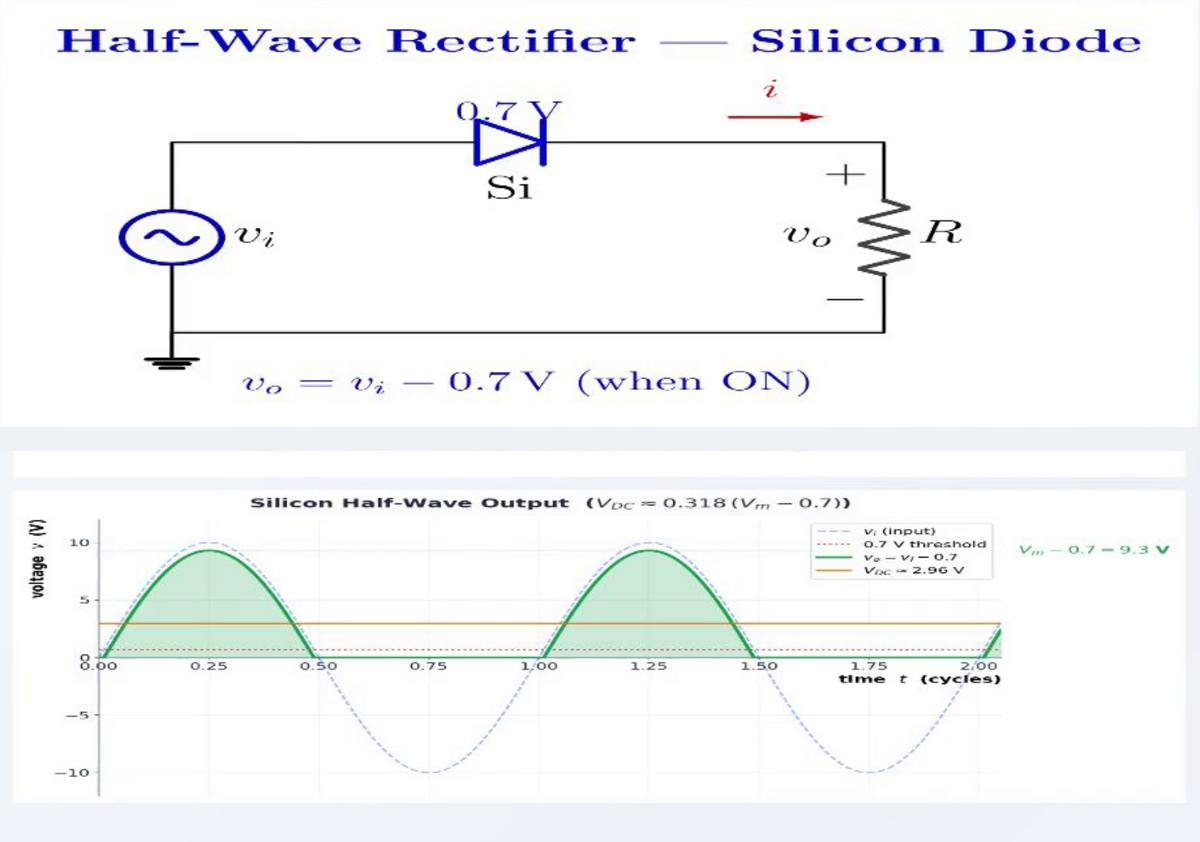
The constant-drop model conducts only after the input exceeds 0.7 V and then gives v_o = v_i − 0.7 V. Silicon model:vi ≤ 0.7 V → diode OFF → vo = 0vi > 0.7 V → diode ONON:Output peak:Conduction lasts slightly less than half a cycleNarration transcript
Now let us swap the ideal diode for a real silicon diode. Same circuit, same AC source, same resistor — only the diode model changes. Silicon does not turn on at zero volts. It needs zero point seven volts of forward bias to start conducting. So during the positive half cycle, the diode does not conduct immediately when v_i goes positive. It waits until v_i reaches zero point seven volts. Only then does it turn on. And once it is on, it drops zero point seven volts across itself. So the output is v_i minus zero point seven. This means two things change. First, the peak of the output is V_m minus zero point seven, not V_m. Second, the diode conducts for slightly less than a full half cycle, because it is off at the beginning and end of each positive hump.
5. Silicon DC estimate

The 0.7 V drop is modest at a 10 V peak but consumes a much larger fraction of a low-amplitude signal. For Vm ≫ 0.7 V:V_m = 10 V → ideal:V_m = 10 V → silicon:Difference ≈ 0.22 VV_m = 2 V → silicon:Low-voltage option: Schottky, VF ≈ 0.3 VNarration transcript
What about V_DC for the silicon case? The math gets a bit messier, but here is the practical engineering answer. When V_m is much larger than zero point seven, we can approximate the output as a half-wave rectified version of v_i minus zero point seven. That gives us V_DC approximately equals zero point three one eight times the quantity V_m minus zero point seven. Let us put numbers on this. Say your AC peak is ten volts. With an ideal diode: V_DC equals zero point three one eight times ten, which is three point one eight volts. With a silicon diode: V_DC equals zero point three one eight times nine point three, which is two point nine six volts. Not a huge difference at ten volts, but at smaller signal levels — say two volts peak — the seven hundred millivolt drop becomes a much bigger fraction of your output. That is why low-voltage rectifiers sometimes use Schottky diodes, with a much smaller drop, around zero point three volts.
6. Summary and next step

Half-wave rectification is the simplest AC-to-DC stage; practical supplies capture both half-cycles and smooth the output. Half-wave rectifier removes one sine half-cycleIdeal:Silicon:Output: pulsating DC with a zero half-cycleNext: full-wave rectifier + smoothing capacitorNarration transcript
Let us recap. A half-wave rectifier turns AC into pulsating DC by chopping off one half of every sine cycle. Just one diode, one resistor, one AC source. With an ideal diode, V_DC equals zero point three one eight times V_m. Where zero point three one eight comes from one over pi. With a silicon diode, the peak shrinks by zero point seven volts, and V_DC drops to roughly zero point three one eight times V_m minus zero point seven. The output is choppy — half the cycle is just zero. In real power supplies, we add a smoothing capacitor and use a full-wave rectifier instead, which captures both halves of the sine wave. That is exactly what we will build in the next lesson. See you there.
Source video: Electronics Basics #03 | Half-Wave Rectifier: Ideal + Silicon, V_DC = 0.318·V_m (5:48)