Circuit Theory 2 · Impedance of ideal R, L and C
#03 Derive element impedances, compare phase and frequency dependence, and check a 1000 rad/s example
Derive Z_R, Z_L and Z_C, identify which waveform leads, then verify the 1000 rad/s example with explicit SI-unit conversion.
Question
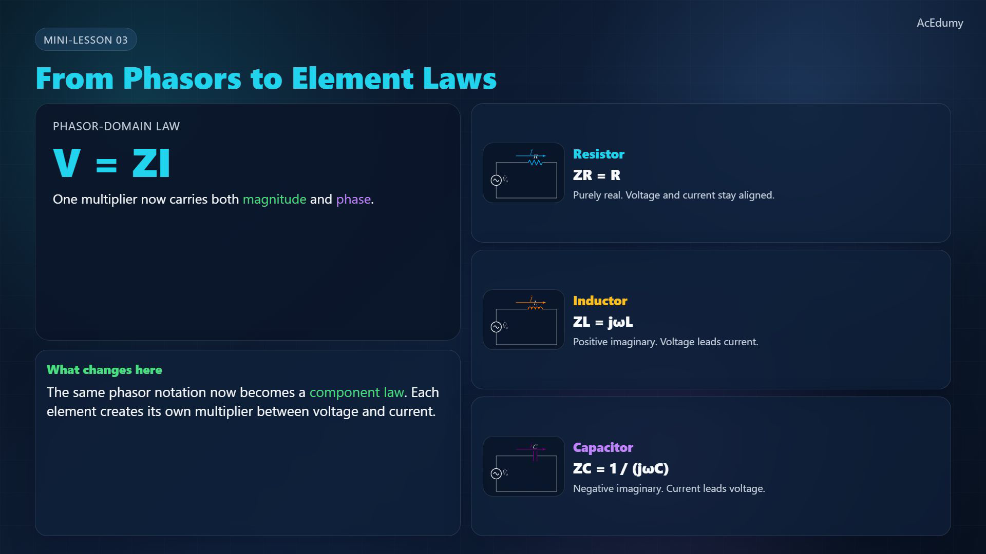
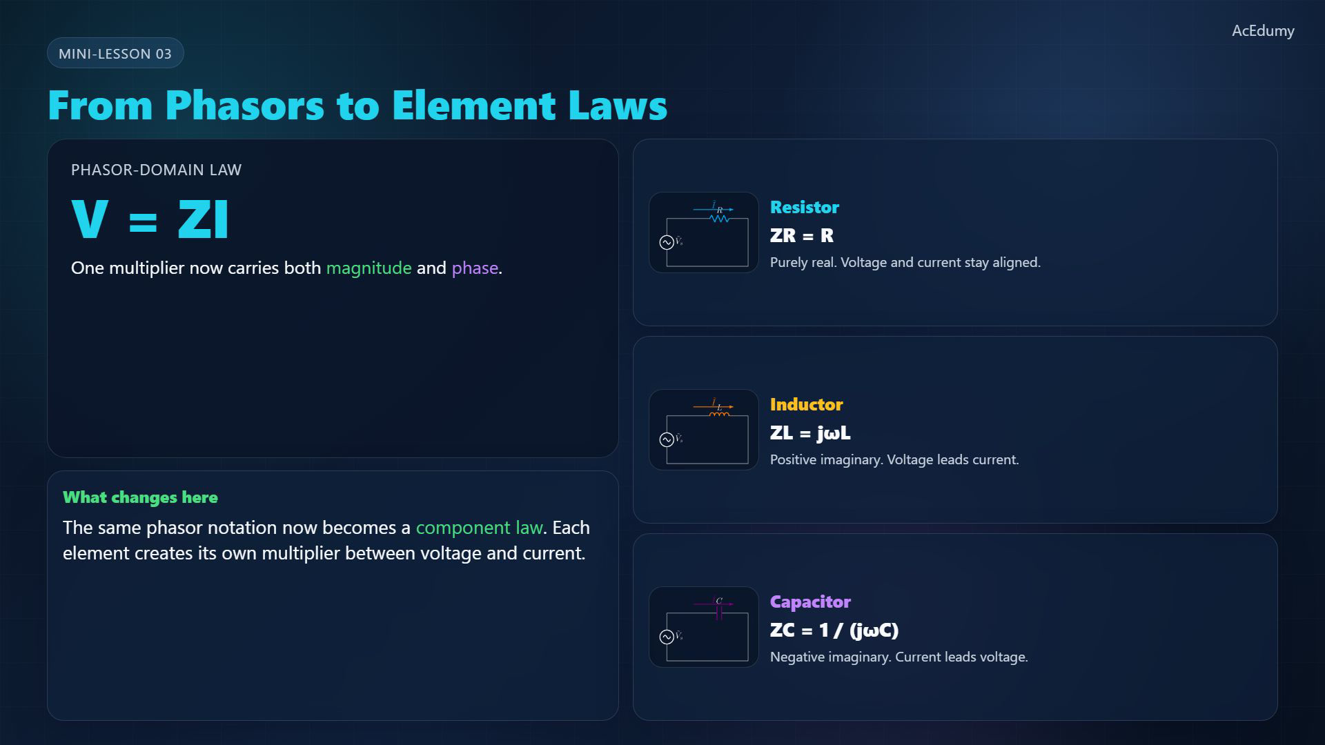
Derive the resistor, inductor and capacitor impedance laws for ideal linear time-invariant elements with positive constant R, L and C, at a common positive angular frequency ω. Use the positive-frequency e^(jωt) convention and the passive sign convention: current enters the positive voltage-reference terminal. Lowercase v(t), i(t) are instantaneous quantities; uppercase V, I are complex phasors, using one common peak or RMS convention. Explain j as the imaginary unit, impedance in ohms, and the difference between impedance and an instantaneous voltage/current ratio. Z=V/I requires I not zero. Derive the +90° and −90° voltage-current phase differences, with phase meaningful only for nonzero phasors. Geometric phase diagrams need equally scaled real and imaginary axes; voltage and current arrow magnitudes have different units. Compare frequency dependence for the ideal model, not all real components at arbitrarily high frequency. Explain zero cycle-average absorbed power for ideal L/C and losses in real components. Convert 10 mH and 100 μF to SI units, then evaluate their impedances at 1000 rad/s step by step. The numeric source card is a legacy reference; readable formulas and model conditions are stated in the notebook. Original video/audio are unchanged.
Written solution and narration transcript(shows the full solution)
Below are all the lines written in the notebook together with the full narration transcript.
1. Define impedance in sinusoidal steady state
Reference from the original video. The notebook spells out ideal-element conditions, voltage/current sign conventions and readable equations; legacy raster cards are not newly corrected diagrams. Apply phasor notation to ideal, linear, time-invariant circuit elements.Use one common sinusoidal frequency and one consistent peak or root-mean-square (RMS) convention for both voltage and current.With current entering the element's positive voltage-reference terminal, the phasor law is:Impedance Z is measured in ohms; the ratio assumes a nonzero current phasor:Impedance encodes a magnitude ratio and a phase difference, not an instantaneous voltage/current ratio.Narration transcript
Now the phasor becomes useful. For any circuit element, we want one compact rule between the voltage phasor and the current phasor. In sinusoidal steady state, that rule is written as V equals Z times I. The multiplier Z is called impedance. It keeps magnitude and phase inside the same object.
2. Resistor: real impedance and aligned phase
Reference from the original video. The notebook spells out ideal-element conditions, voltage/current sign conventions and readable equations; legacy raster cards are not newly corrected diagrams. Start with an ideal resistor of constant positive resistance R.Instantaneous voltage and current obey:No derivative is needed; the same linear law holds for the phasors:Its impedance is real and positive:For nonzero sinusoidal voltage and current, their phase difference is zero.Voltage and current phasors have the same direction. Their arrow lengths use different physical units, volts and amperes.Narration transcript
Start with the resistor. In the time domain, v equals R i. Nothing differentiates or integrates here, so the phasor form stays simple: V equals R I. The impedance of a resistor is just R. It is purely real, and voltage and current are in phase. Their phasors point in the same direction.
3. Inductor: derive the positive imaginary impedance

Reference from the original video. The notebook spells out ideal-element conditions, voltage/current sign conventions and readable equations; legacy raster cards are not newly corrected diagrams. For an ideal inductor, take constant positive inductance L.Using the passive sign convention, the instantaneous law is:With the positive-frequency convention, differentiation contributes jω:Therefore the inductor's impedance is:At positive frequency, j gives a +90° impedance angle; voltage leads current by 90°. A geometric phase-angle plot requires equally scaled real and imaginary axes.At fixed L, impedance magnitude grows with angular frequency:Narration transcript
Now the inductor. In the time domain, v equals L d i over d t. A derivative in sinusoidal steady state contributes a factor of j omega, so the phasor equation becomes V equals j omega L I. That means the impedance of an inductor is Z sub L equals j omega L. The j places it on the positive imaginary axis, and voltage leads current by ninety degrees. As frequency rises, the inductive magnitude grows.
4. Capacitor: derive the negative imaginary impedance

Reference from the original video. The notebook spells out ideal-element conditions, voltage/current sign conventions and readable equations; legacy raster cards are not newly corrected diagrams. For an ideal capacitor with constant positive capacitance C, the passive-sign law is:The corresponding positive-frequency phasor law is:For nonzero frequency, divide by jωC; because 1/j=−j, the impedance is:Its impedance angle is −90°; voltage lags current by 90°, equivalently current leads voltage by 90°.At fixed C, its magnitude falls as angular frequency rises:Narration transcript
For the capacitor, the time-domain law starts as i equals C d v over d t. So in phasor form, I equals j omega C V. Rearranging gives V equals one over j omega C times I, so the impedance is Z sub C equals one over j omega C, or negative j over omega C. Capacitive impedance lies on the negative imaginary axis, and current leads voltage by ninety degrees. As frequency rises, its magnitude gets smaller.
5. Compare phase, frequency and energy behavior

Reference from the original video. The notebook spells out ideal-element conditions, voltage/current sign conventions and readable equations; legacy raster cards are not newly corrected diagrams. Compare the ideal elements at a common positive frequency.A positive resistance has a positive real impedance.Inductive impedance lies on the positive imaginary axis.Capacitive impedance lies on the negative imaginary axis.A resistor dissipates energy. Ideal L and C store and return energy, with zero average absorbed power over a steady-state cycle; real components also have losses.For this constant-element ideal model, R is frequency-independent, |ZL| grows, and |ZC| decreases. These are not universal high-frequency models of real components.Narration transcript
Now compare the three. Resistance sits on the real axis. Inductive reactance points upward on the imaginary axis. Capacitive reactance points downward. The resistor dissipates power, while the inductor and capacitor mainly store and return energy. Frequency does not move R, but it pushes the magnitude of Z sub L up and pulls the magnitude of Z sub C down.
6. Check the 1000 rad/s example with units
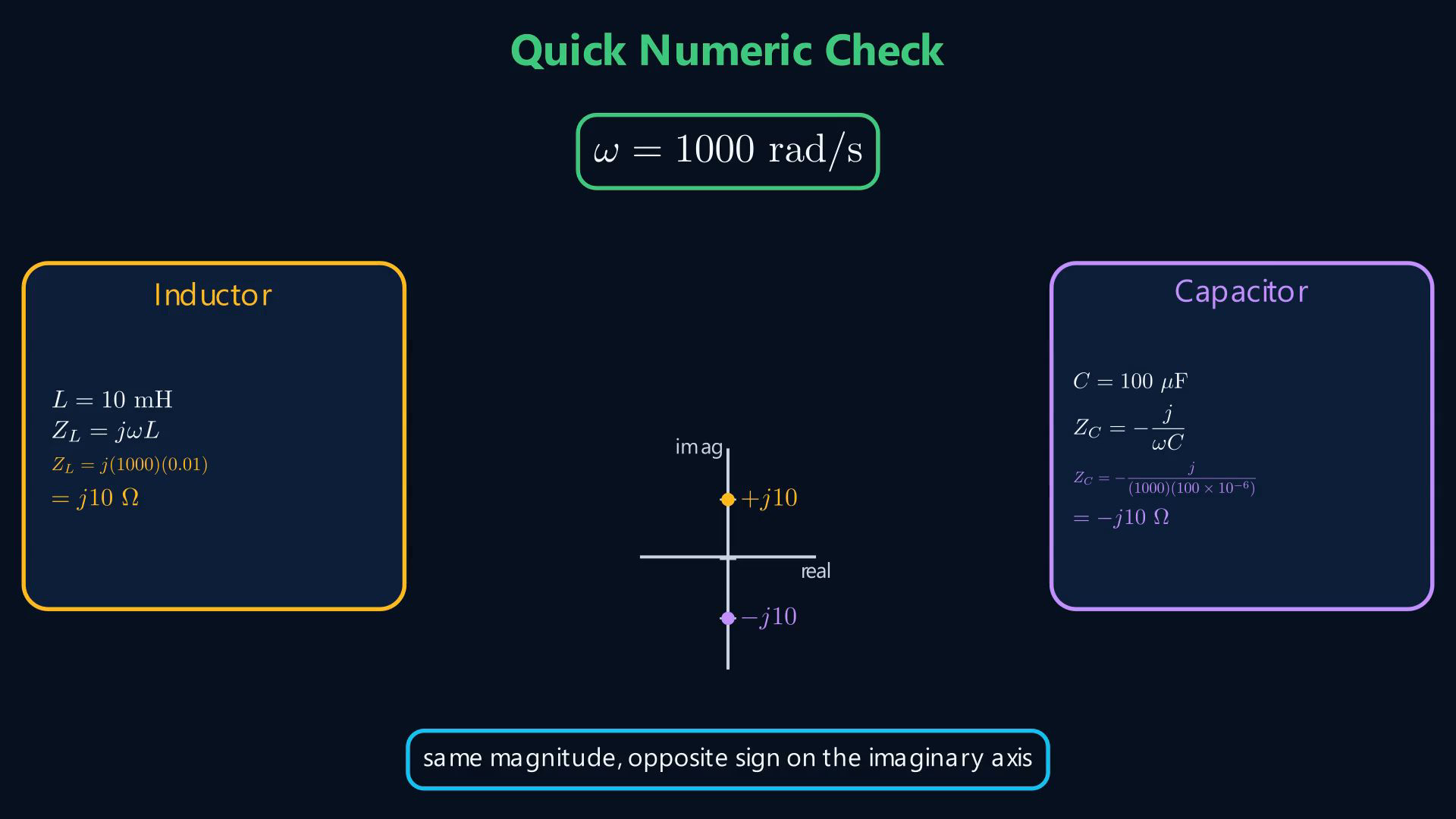
Reference from the original video. The notebook spells out ideal-element conditions, voltage/current sign conventions and readable equations; legacy raster cards are not newly corrected diagrams. Use angular frequency in radians per second, not hertz:Convert L=10 mH to 0.01 H before substituting:Convert C=100 μF to 0.0001 F, then evaluate the denominator:Both magnitudes are 10 Ω, but their impedance angles are +90° and −90°, respectively.Opposite imaginary signs explain opposite voltage-current phase shifts; L and C themselves remain positive real component values.Narration transcript
Take a quick numeric check at omega equals one thousand radians per second. If L equals ten millihenries, then Z sub L equals j ten ohms. If C equals one hundred microfarads, then Z sub C equals negative j ten ohms. Same magnitude, opposite imaginary direction. That sign difference is exactly why inductors and capacitors affect phase in opposite ways.
7. Connect element impedances to AC circuit equations

Reference from the original video. The notebook spells out ideal-element conditions, voltage/current sign conventions and readable equations; legacy raster cards are not newly corrected diagrams. Impedance multiplies a current phasor to give the corresponding voltage phasor at the chosen frequency.For positive R, L, C and positive frequency: ZR is positive real, ZL is positive imaginary, and ZC is negative imaginary. L and C are not imaginary-valued components.Next: alternating-current (AC) Kirchhoff's voltage law (KVL), Kirchhoff's current law (KCL), nodal analysis and mesh equations.Narration transcript
Impedance is the phasor-domain multiplier between voltage and current. For R it is real, for L it is positive imaginary, and for C it is negative imaginary. In the next lesson, we will place these impedances inside A C K V L, node, and mesh equations.
Source video: Circuit Theory-2 #03 Impedance of R, L, and C (3:27)