Circuit Theory 1 · Operational Amplifiers
#32 Operational Amplifiers #32 — Inverting op-amp gain
Derives the inverting gain from conditional virtual ground and zero input current, then solves a 5 V example with a rail check.
Question
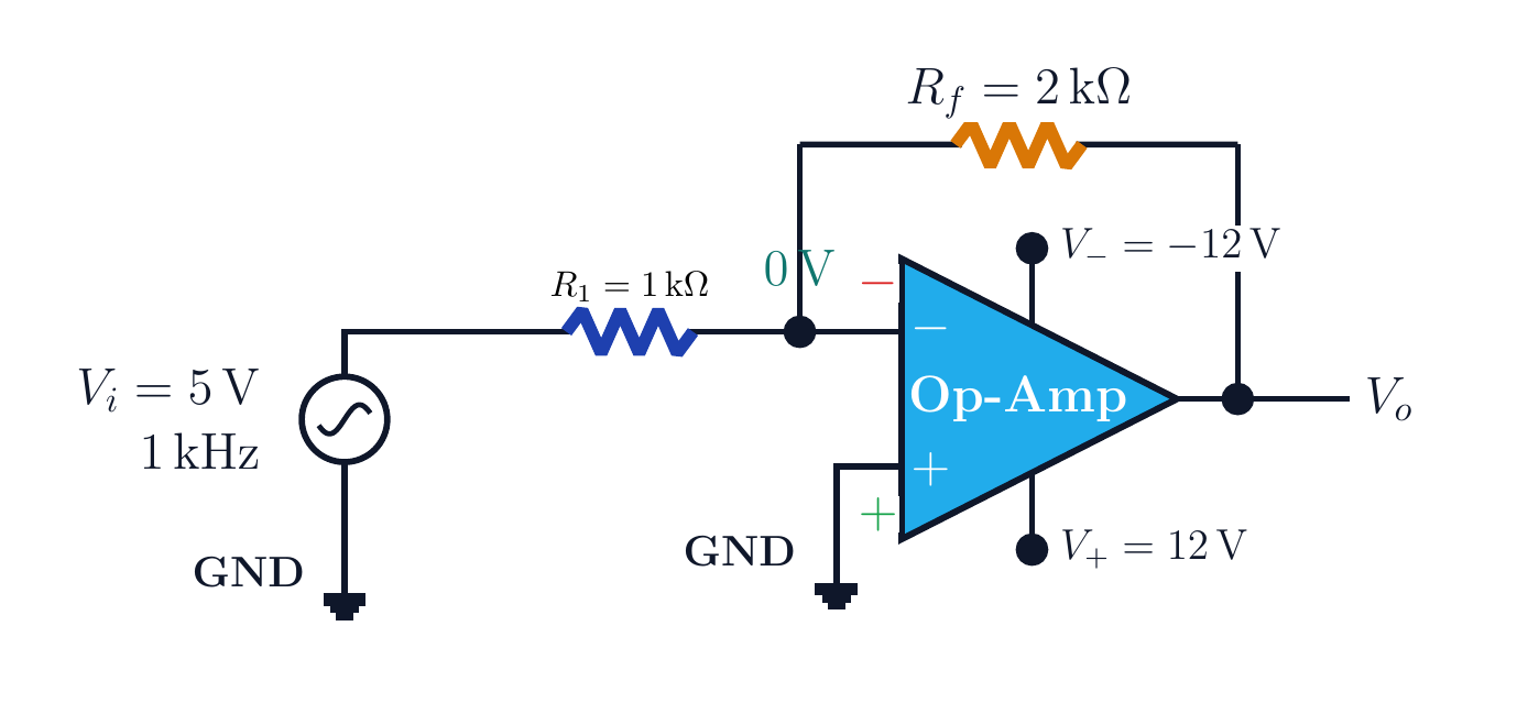
For an ideal inverting op amp with the plus input grounded, input resistor R_1, and feedback resistor R_f, derive V_o/V_i. Find the output for V_i=5 V, R_1=1 kΩ, R_f=2 kΩ, and ±12 V supplies, then interpret the rail limit.
Written solution and narration transcript(shows the full solution)
Below are all the lines written in the notebook together with the full narration transcript.
1. Question and circuit
The circuit is used to calculate gain and check whether the ideal output fits within the rails. Inverting op-amp questionVi → R1 → minus inputPlus input → groundRf feeds Vo back to the minus nodeFind Vo and AvNarration transcript
Here is the exact question for this lesson. We have an inverting op amp. The input signal is V i. It passes through R one into the minus input node. The plus input is grounded. A feedback resistor R f brings the output back to that same minus node. First, we want the general relation between V output and V input. Then, in the example, we use V i equal to five volts, R one equal to one kilo ohm, and R f equal to two kilo ohms. We will find V output and the voltage gain, step by step.
2. Conditional virtual ground
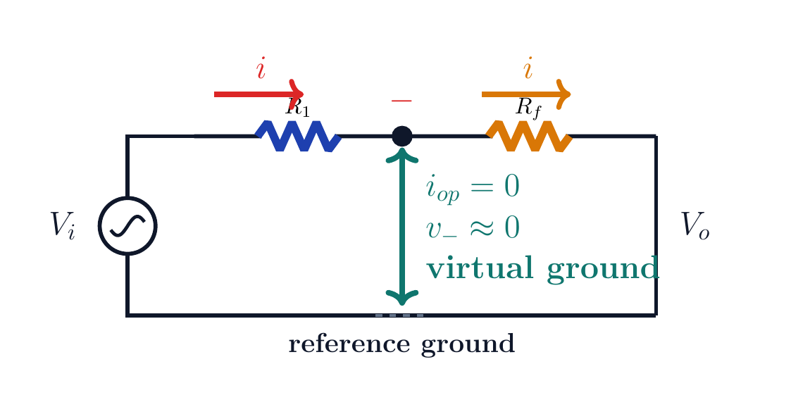
Zero ideal input current allows the two resistor currents to be equated at the node. Conditional virtual groundNegative feedback is requiredOperation must be linear and unsaturatedIdeal model:It is not a physical ground connectionNarration transcript
The central idea is virtual ground. Let us say it carefully, because this is where many students get lost. The plus input is physically connected to ground, so v plus is zero volts. With negative feedback and an ideal op amp in its linear region, the op amp drives its output until v minus becomes almost equal to v plus. Therefore the minus input node is approximately zero volts. It is not a wire to ground, but its voltage is almost zero. That is why we call it virtual ground.
3. Current continuity
Zero ideal input current allows the two resistor currents to be equated at the node. Current continuity at the nodeIdeal input current:R1 current must continue through RfThe minus sign preserves polarityNarration transcript
Now look at the current. In the ideal model, no current enters the op amp input. So the current that comes through R one has only one place to go: through R f toward the output. That is why the two resistor currents are equal. We write the left current as V i minus zero, divided by R one. We write the feedback current as zero minus V output, divided by R f. Since the currents are the same, those two fractions are equal.
4. Gain derivation
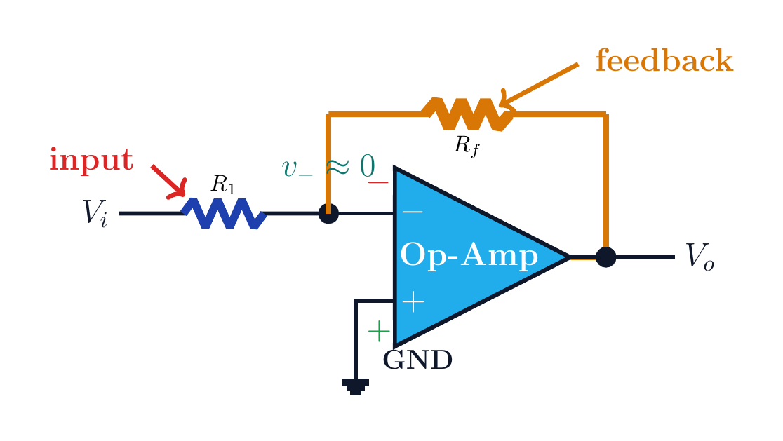
R_f feeds the output back to the minus node; v_-≈0 is valid only under the required operating conditions. Derive the inverting gainMinus sign: 180° phase reversalNarration transcript
Now solve that equation without skipping the sign. V i over R one equals negative V output over R f. Multiply both sides by R f. R f over R one times V i equals negative V output. Move the minus sign to the other side, and we get V output equals negative R f over R one times V input. The voltage gain is therefore A v equals V output over V input, which is negative R f over R one. The minus sign is the inversion.
5. Numerical example
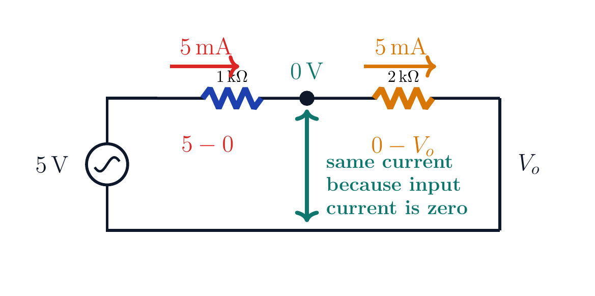
Zero input current at the virtual-ground node provides current continuity. Numerical examplei=5 V/1 kΩ=5 mA(5 mA)(2 kΩ)=10 VCurrent and gain checks agreeNarration transcript
Now plug in the numbers from the example. R f over R one is two kilo ohms divided by one kilo ohm. The kilo units cancel, so the ratio is two. Therefore V output equals negative two times V input. If V input is five volts, then V output is negative ten volts. Equivalently, the input current is five volts divided by one kilo ohm, which is five milliamps. The same five milliamps through two kilo ohms gives ten volts across R f, and the output side must be negative.
6. Supply check
The circuit is used to calculate gain and check whether the ideal output fits within the rails. Supply-rail checkIdeal demand:The ideal rail test passesExceeding a rail causes saturation and clippingCheck practical output swing in the data sheetNarration transcript
Before we accept the answer, check the supply rails. The op amp is powered from plus twelve volts and minus twelve volts. Our calculated output amplitude is ten volts. Ten volts is inside the twelve volt limit, so the ideal result is possible here. If the calculation had asked for, say, fifteen volts, the real output would clip near the rail. In this example, negative ten volts is safe.
7. Waveform
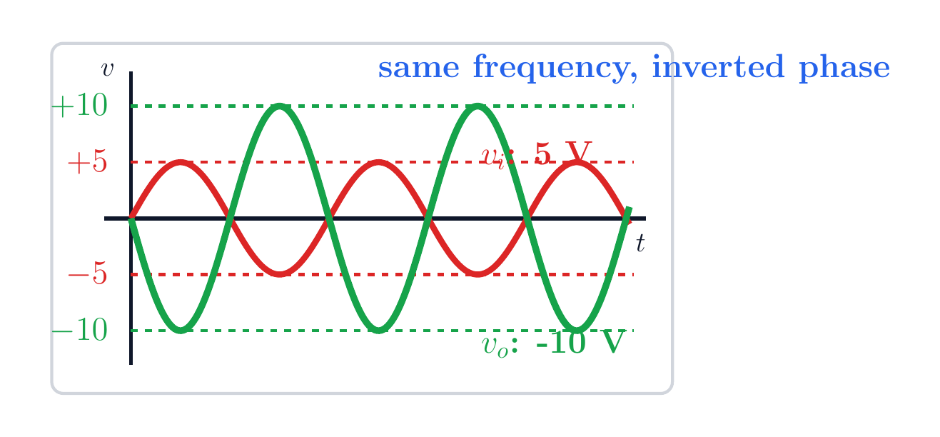
A gain of negative two preserves frequency, doubles amplitude, and reverses phase by 180 degrees. Read the waveformfo=fi=1 kHzAv<0 → phase reversalPositive input gives negative output5 V peak → ideal 10 V peakNarration transcript
What does that mean for the sine wave? The frequency does not change: it is still one kilohertz. The amplitude doubles because the magnitude of the gain is two. But the minus sign flips the waveform. So when the input is positive, the output is negative; when the input is negative, the output is positive. In short, V output is an inverted sine wave with twice the amplitude of V input.
8. Method summary
R_f feeds the output back to the minus node; v_-≈0 is valid only under the required operating conditions. Method summary1. Verify conditional virtual ground2. Continue current using iin=03. Solve KCL with its signHere Av=−2 and Vo=−10 VFinal check: rails and practical output swingNarration transcript
The inverting op amp is one of the most important op amp patterns. Read it with three ideas. First, the plus input is grounded. Second, negative feedback makes the minus node a virtual ground. Third, because op amp input current is zero, the current through R one must continue through R f. From those three ideas, the formula follows naturally: V output equals negative R f over R one times V input. For this example, the gain is negative two and the output is negative ten volts for a five volt input.
Source video: Circuit Theory #32 | Inverting Op-Amp: Gain Formula and 5 V Example (4:46)