Digital Design · Logic Gates and Complete Truth Tables
#03 Evaluate all eight rows of an AND–OR–NOT circuit and compare fundamental gate contracts
Translate gate rules into complete truth tables, solve a three-input combinational circuit and explain why NAND or NOR networks are universal.
Question
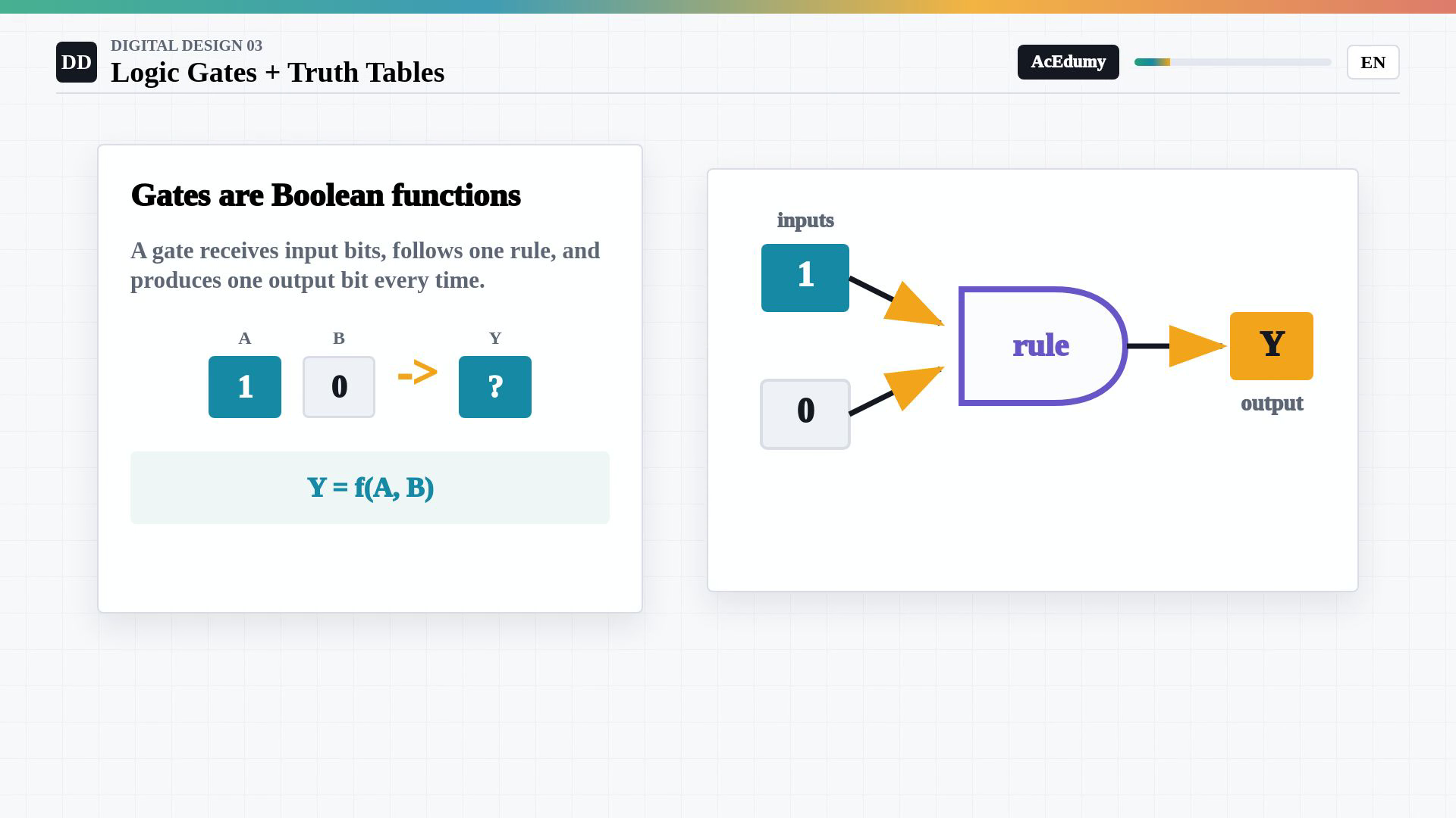
Use an ideal combinational Boolean model with valid stable binary inputs. Explain NOT, AND, inclusive OR, NAND, NOR and two-input XOR, and give each complete truth table. For n independent binary inputs, an uncompressed truth table contains2^n input combinations. Each output bit is a deterministic function of the current inputs. This logical model does not claim zero physical propagation delay, valid behavior outside electrical input limits, or the absence of transient glitches. Sequential circuits additionally depend on stored state and are outside this worked combinational example. Solve Y=(A AND B) OR (NOT C). Compute P=A AND B and Q=NOT C before the final inclusive OR. Use rows(A,B,C)=000,001,010,011,100,101,110,111. The P column is0,0,0,0,0,0,1,1; Q is1,0,1,0,1,0,1,0; Y is1,0,1,0,1,0,1,1. If C=0, Q=1 forces Y=1 for every A,B. If C=1, Q=0 and Y=A AND B, so among those four rows only111 gives output1. The source's only111 statement belongs to the preceding C=1 case; row110 also has AND output1 but already has Q=1. Output0 occurs exactly at001,011,101. Do not replace the final OR with AND or XOR. In the displayed equations, addition, subtraction and multiplication are ordinary arithmetic restricted to variables in{0,1}. NOT(A)=1-A,AND(A,B)=A*B,OR(A,B)=A+B-A*B,NAND(A,B)=1-A*B,NOR(A,B)=(1-A)*(1-B),andXOR(A,B)=A+B-2*A*B. Thus Y=P+Q-P*Q=A*B+(1-C)-A*B*(1-C)=1-C+A*B*C. In conventional Boolean-algebra notation a plus sign can instead denote inclusive OR; explicitly distinguish the conventions. In particular ordinary1+1 is2, while Boolean1 OR1 is1. XOR means unequal inputs for two inputs; a repeated XOR with more inputs computes odd parity and is not a general all-inputs-different test. NAND and NOR are each functionally complete when multiple gates and ordinary wiring, including connecting both inputs to the same signal, are allowed. One isolated two-input gate does not implement an arbitrary multi-input function. With only NAND, obtain NOT A by NAND(A,A),AND by inverting NAND,and OR by NAND of the inverted inputs. With only NOR, obtain NOT A by NOR(A,A),OR by inverting NOR,and AND by NOR of the inverted inputs. These constructions plus a complete sum-of-products representation establish universality. This is a logical realizability result, not a guarantee of minimum area, shortest delay or glitch-free behavior. The first rule pictogram is schematic and leaves f unspecified: its question-mark output is not an additional logic value. The gate-symbol cards show independent symbols and tables. The worked diagram explicitly connects A and B to AND,C to NOT,and the two intermediate outputs to OR. Use its complete truth table and the gate connectivity together. Keep the worked answer within the supplied binary model.
Written solution and narration transcript(shows the full solution)
Below are all the lines written in the notebook together with the full narration transcript.
1. Treat gates as Boolean functions
The ideal combinational model uses valid binary inputs. Inclusive OR, inversion and AND determine each output. The worked circuit combines A AND B with NOT C through OR, and its full eight-row table shows every case. Move from number representations to logic inputs.A bit can serve as a logic input.Gate function:Valid input bits determine one output according to the gate rule.Use input labels A, B and C.Call the output Y.The ideal rule depends on bit values, not their previous use.For valid steady inputs, the same rule gives the same output.Compose reliable logic from defined gate behavior.Narration transcript
In the last lesson, bits became numbers. Now the same bits become logic inputs. A logic gate is a tiny Boolean function. It receives one or more input bits, applies a rule, and produces one output bit. We usually name the inputs A, B, and sometimes C. The output is often called Y. The important shift is this: a gate does not care where the bit came from. It only sees zero or one, then follows its rule every time. That repeatable rule is what lets us build reliable digital circuits from simple parts.
2. Apply NOT, AND and inclusive OR
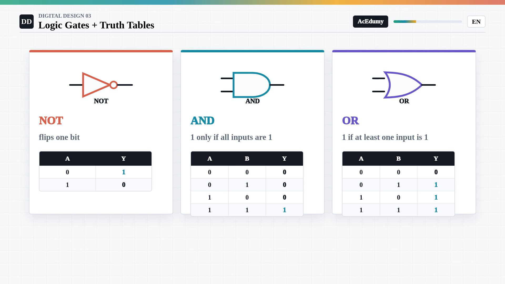
The ideal combinational model uses valid binary inputs. Inclusive OR, inversion and AND determine each output. The worked circuit combines A AND B with NOT C through OR, and its full eight-row table shows every case. Review NOT, AND and inclusive OR.NOT rule:AND requires all inputs to be one.Two-input AND:Inclusive OR requires at least one input to be one.Two-input OR:Use NOT, AND and OR as precise Boolean operations.These rules describe the logical behavior implemented by gates.Narration transcript
Start with the three basic ideas. NOT flips one bit: zero becomes one, and one becomes zero. AND is strict. Its output is one only when all inputs are one. OR is permissive. Its output is one when at least one input is one. These three rules already feel like small sentences: not this, this and that, this or that. Digital design turns those sentences into hardware.
3. Enumerate the complete truth table
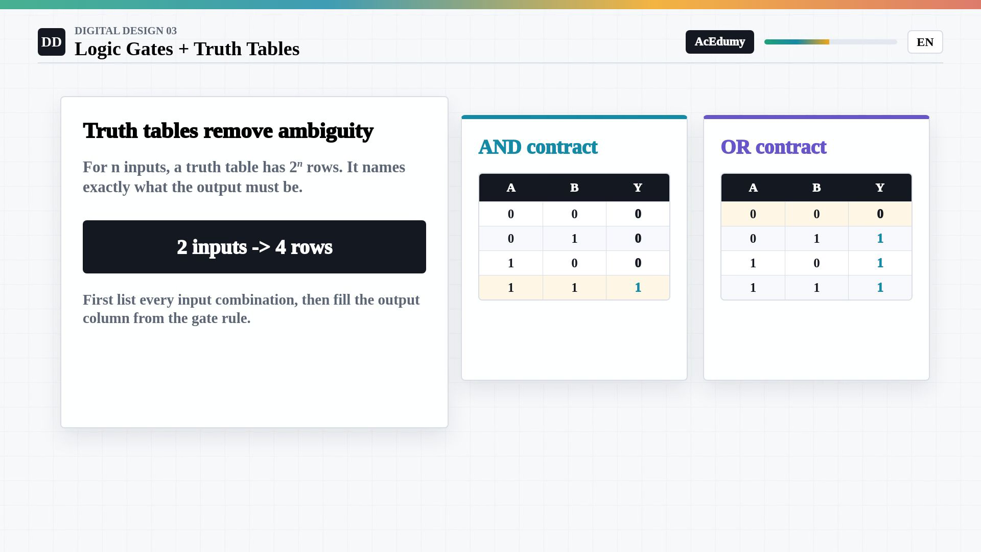
The ideal combinational model uses valid binary inputs. Inclusive OR, inversion and AND determine each output. The worked circuit combines A AND B with NOT C through OR, and its full eight-row table shows every case. Use a complete truth table as the combinational function contract.List every binary input combination and its required output.Two-input row count:For AND, only the input row one, one gives output one.For inclusive OR, every input row except zero, zero gives output one.Check each row against the gate rule to resolve logical ambiguity.Narration transcript
A truth table is the contract for a gate or a whole combinational block. It lists every possible input combination and the output that must happen for each one. With two inputs, there are four rows: zero zero, zero one, one zero, and one one. For AND, only the last row gives one. For OR, every row except zero zero gives one. When a diagram feels confusing, the truth table is the clean way to remove all ambiguity.
4. Evaluate an AND–OR–NOT circuit
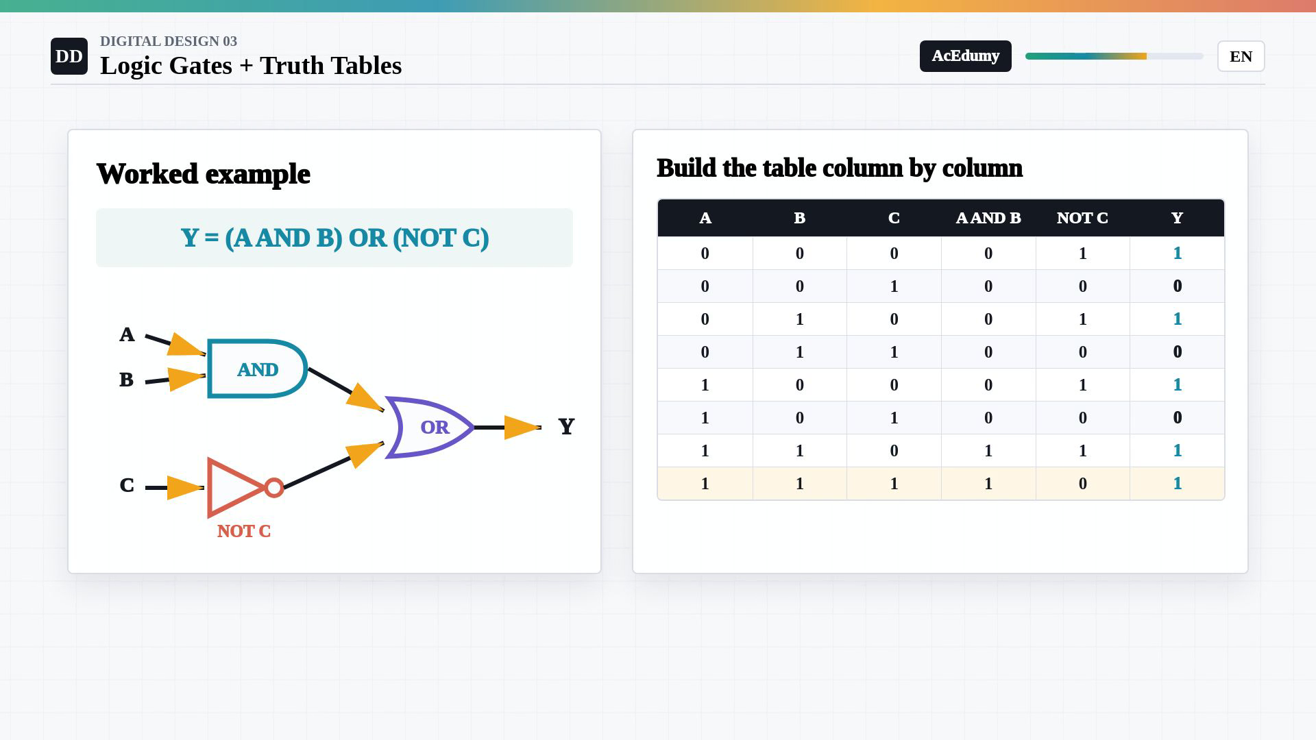
The ideal combinational model uses valid binary inputs. Inclusive OR, inversion and AND determine each output. The worked circuit combines A AND B with NOT C through OR, and its full eight-row table shows every case. Evaluate the example through its intermediate signals.Combined output:AND intermediate:Inverted input:Final inclusive OR:When C is zero, Q is one and all four choices of A and B give output one.When C is one, Q is zero and the output equals A AND B.Among rows with C equal to one, only A and B both one give output one.In input order zero-zero-zero through one-one-one, the outputs are one, zero, one, zero, one, zero, one, one.Narration transcript
Now let us solve a small circuit. The expression is: Y equals A AND B, OR NOT C. First compute A AND B. Then compute NOT C. Finally OR those two intermediate results together. If C is zero, NOT C is one, so the final output is automatically one. If C is one, NOT C is zero, and the output depends on A AND B. That means only the row A equals one, B equals one, C equals one still produces one through the AND path. The table makes the behavior visible.
5. Use NAND, NOR and two-input XOR
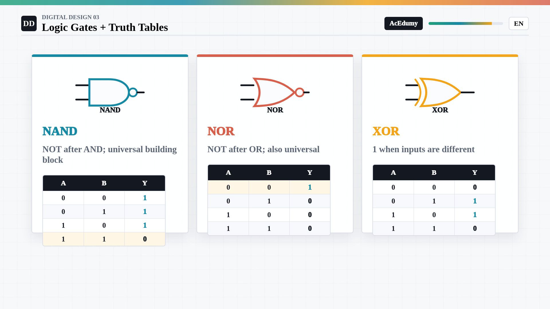
The ideal combinational model uses valid binary inputs. Inclusive OR, inversion and AND determine each output. The worked circuit combines A AND B with NOT C through OR, and its full eight-row table shows every case. Add NAND and NOR, then compare two-input XOR.Two-input NAND:NAND is zero only when both inputs are one.Two-input NOR:NOR is one only when both inputs are zero.Two-input XOR:Networks using only NAND, or only NOR, can implement any finite Boolean function.Functional completeness provides alternative ways to construct combinational logic.Narration transcript
Two more gates appear constantly. NAND means NOT after AND. It is zero only when all inputs are one. NOR means NOT after OR. It is one only when all inputs are zero. XOR is the difference detector: with two inputs, it outputs one when the inputs are different. NAND and NOR are especially powerful because each one can build every other Boolean function. That idea will matter later when we design real circuits efficiently.
6. Compose combinational functions

The ideal combinational model uses valid binary inputs. Inclusive OR, inversion and AND determine each output. The worked circuit combines A AND B with NOT C through OR, and its full eight-row table shows every case. Keep the function, table and composition viewpoints together.Gates implement Boolean functions.A complete truth table states the required logical outputs.A combinational network of gates still defines a function of its current valid inputs.Boolean algebra and De Morgan identities can rewrite logic while preserving the truth table.Narration transcript
Here is the mental model. Gates are Boolean functions. Truth tables are their exact contracts. Small gates combine into larger combinational blocks, and those blocks still have truth tables. In the next lesson we will stop drawing every row by hand and begin using Boolean algebra, including De Morgan's laws, to rewrite logic without changing its behavior.
Source video: Digital Design #03 | Logic Gates and Truth Tables (3:30)