Communication Basics · Microwave Link Budget: FSL, RSL, and Fade Margin
#24 calculate 96.6-dB free-space loss at one mile and 1 GHz, −50-dBm received signal level from gain/loss bookkeeping, and 20-dB fade margin against −70-dBm sensitivity while separating dB/dBm/dBi, conditional band selection, and availability-based design
Build the one-mile/1-GHz link budget with correct dB/dBm/dBi references, verify 96.6-dB FSL, −50-dBm RSL, and 20-dB margin, then bound the result by availability-driven field conditions.
Question
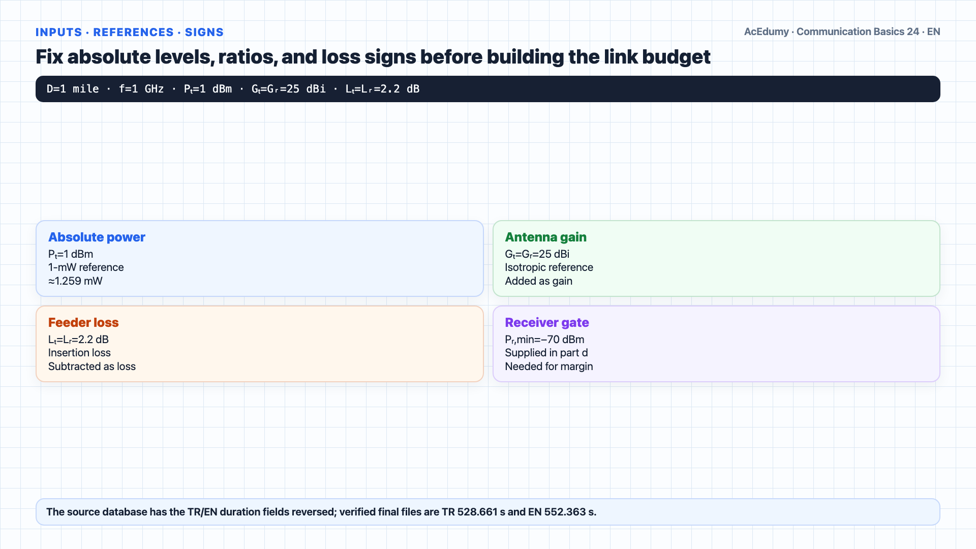
Distinguish the dB power ratio, dBm absolute power level, and dBi isotropic-referenced antenna gain; show that FSL=96.6+20log10(D_mile)+20log10(f_GHz)=96.6 dB at one mile and 1 GHz; calculate RSL=1 dBm−2.2 dB+25 dBi−96.6 dB+25 dBi−2.2 dB=−50 dBm and fade margin=−50−(−70)=20 dB; interpret the L-band and millimetre-wave choices only while other variables and spectrum allocation are fixed; replace the universal 10–20-dB rule with rain, gas, multipath, terrain/Fresnel, availability, receiver-threshold, and implementation-loss gates.
Written solution and narration transcript(shows the full solution)
Below are all the lines written in the notebook together with the full narration transcript.
1. Fix the inputs, signs, and logarithmic reference units
Verify the free-space arithmetic, but do not generalize band or fade-margin decisions independently of spectrum, antenna, propagation, threshold, and availability conditions. Welcome back.Today we solve the classic microwave link budget problem.Here is the setup.We have a one mile microwave link operating at one gigahertz.The transmitter output power is one decibel milliwatt.Both the transmitting and receiving antenna gains are twenty five decibel isotropic.The cabling loss at the transmitter and at the receiver is two point two decibels each.We have five questions.Part a: which frequency band would you choose for the longest possible link?Part b: which band for the highest information bandwidth?Part c: find the received signal level, or RSL.Part d: if the receiver sensitivity threshold is negative seventy decibel milliwatt, find the fade margin.Part e: which is the better design, part c or part d?Narration transcript
Welcome back. Today we solve the classic microwave link budget problem. Here is the setup. We have a one mile microwave link operating at one gigahertz. The transmitter output power is one decibel milliwatt. Both the transmitting and receiving antenna gains are twenty five decibel isotropic. The cabling loss at the transmitter and at the receiver is two point two decibels each. We have five questions. Part a: which frequency band would you choose for the longest possible link? Part b: which band for the highest information bandwidth? Part c: find the received signal level, or R S L. Part d: if the receiver sensitivity threshold is negative seventy decibel milliwatt, find the fade margin. Part e: which is the better design, part c or part d?
2. Separate the dB ratio, dBm power level, and dBi antenna gain
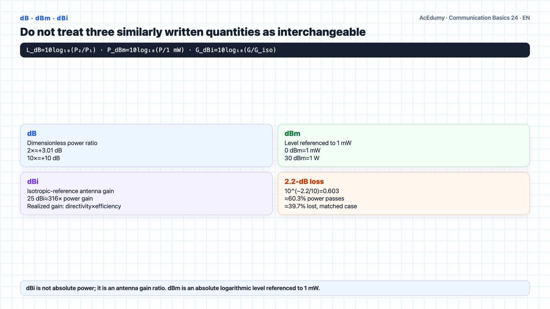
Verify the free-space arithmetic, but do not generalize band or fade-margin decisions independently of spectrum, antenna, propagation, threshold, and availability conditions. Before we plug numbers in, let us understand our units.The three quantities differ: dB is a dimensionless power ratio, dBm is an absolute level referenced to 1 mW, and dBi is antenna gain relative to an isotropic radiator.They look alike but mean different things.dB — decibel — is a ratio.It measures how one power compares to another on a logarithmic scale.The formula: value in dB equals ten times log base ten of the power ratio.Double your power, that is plus three dB.Ten times more, plus ten dB.A hundred times more, plus twenty dB.For 2.2-dB insertion loss, Pout/Pin=10(−2.2/10)≈0.603; under matched conditions about 39.7% is lost and 60.3% is transmitted.dBm is the absolute power level PdBm=10log10(P/1 mW).It means dB above one milliwatt.So zero dBm is exactly one milliwatt.Plus ten dBm is ten milliwatts.Plus thirty dBm is one watt.When we say the transmitter output is one dBm, we mean about one point two six milliwatts of real power.dBi is antenna gain, specifically referenced to an isotropic radiator — a perfect sphere that radiates equally in every direction.25 dBi is a 10(25/10)≈316 power-gain ratio in the stated direction relative to isotropic; realized gain combines directivity and efficiency.It is still a dimensionless ratio, expressed in dB.Narration transcript
Before we plug numbers in, let us understand our units. This problem mixes three closely related symbols: d B, d B m, and d B i. They look alike but mean different things. d B — decibel — is a ratio. It measures how one power compares to another on a logarithmic scale. The formula: value in d B equals ten times log base ten of the power ratio. Double your power, that is plus three d B. Ten times more, plus ten d B. A hundred times more, plus twenty d B. A cable loss of two point two d B means the cable absorbs about forty percent of the incoming power — the rest gets through. d B m is an absolute power unit. It means d B above one milliwatt. So zero d B m is exactly one milliwatt. Plus ten d B m is ten milliwatts. Plus thirty d B m is one watt. When we say the transmitter output is one d B m, we mean about one point two six milliwatts of real power. d B i is antenna gain, specifically referenced to an isotropic radiator — a perfect sphere that radiates equally in every direction. Twenty five d B i means the antenna concentrates power about three hundred times more than the isotropic reference, in its main direction. It is still a dimensionless ratio, expressed in d B.
3. Build reference-aware logarithmic link-budget bookkeeping
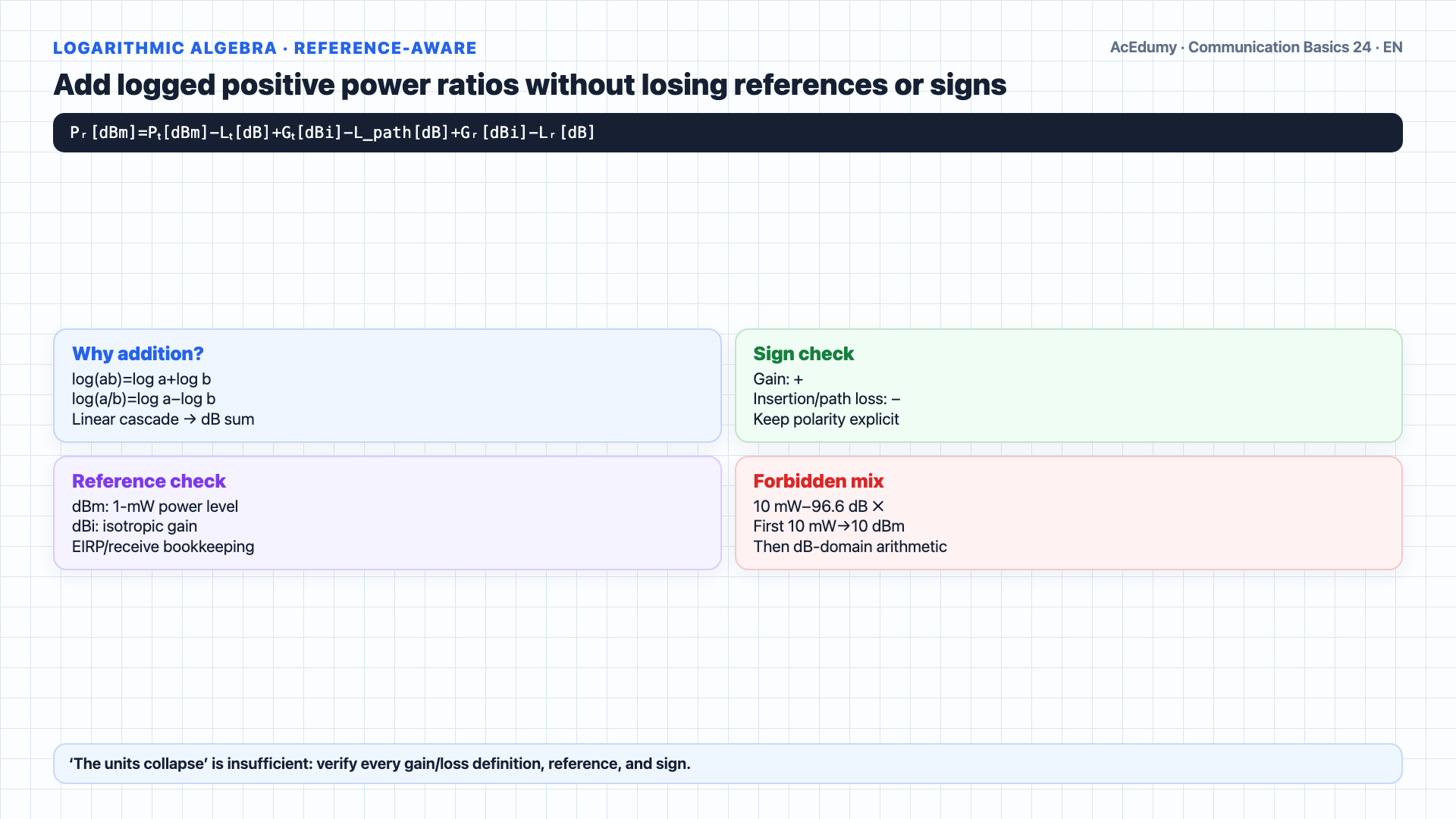
Verify the free-space arithmetic, but do not generalize band or fade-margin decisions independently of spectrum, antenna, propagation, threshold, and availability conditions. Now the trick that makes link budgets simple.For positive power ratios, logarithms turn products into sums and quotients into differences; keep every reference and sign explicit.The unit algebra goes like this.Start with transmit power in dBm, an absolute unit.Subtract cable loss in dB — absolute minus ratio stays absolute, still dBm.Adding dBi gain to a dBm level is valid inside isotropic-referenced EIRP/receive-gain bookkeeping and yields another dBm power level.Subtract free space loss in dB — still dBm.Every term lines up so the final answer stays in dBm.That is why our RSL equation works: dBm minus dB plus dBi minus dB plus dBi minus dB, all of it adds up to dBm.The arithmetic is valid only when each dB term has the correct gain/loss sign and reference; never add linear mW directly to dB.One warning: never mix linear and dB units in the same expression.If you start with ten milliwatts and try to subtract ninety six point six decibels, stop.Stay in the dB world all the way through — then convert back to milliwatts at the very end only if you really need to.Narration transcript
Now the trick that makes link budgets simple. Because logarithms turn multiplication into addition, every multiply or divide in the linear world becomes an add or subtract in the d B world. The unit algebra goes like this. Start with transmit power in d B m, an absolute unit. Subtract cable loss in d B — absolute minus ratio stays absolute, still d B m. Add antenna gain in d B i — absolute plus ratio stays absolute, still d B m. Subtract free space loss in d B — still d B m. Every term lines up so the final answer stays in d B m. That is why our R S L equation works: d B m minus d B plus d B i minus d B plus d B i minus d B, all of it adds up to d B m. You can trust the arithmetic because the units always collapse the same way. One warning: never mix linear and d B units in the same expression. If you start with ten milliwatts and try to subtract ninety six point six decibels, stop. Stay in the d B world all the way through — then convert back to milliwatts at the very end only if you really need to.
4. Trace the gain and loss chain from transmitter to receiver
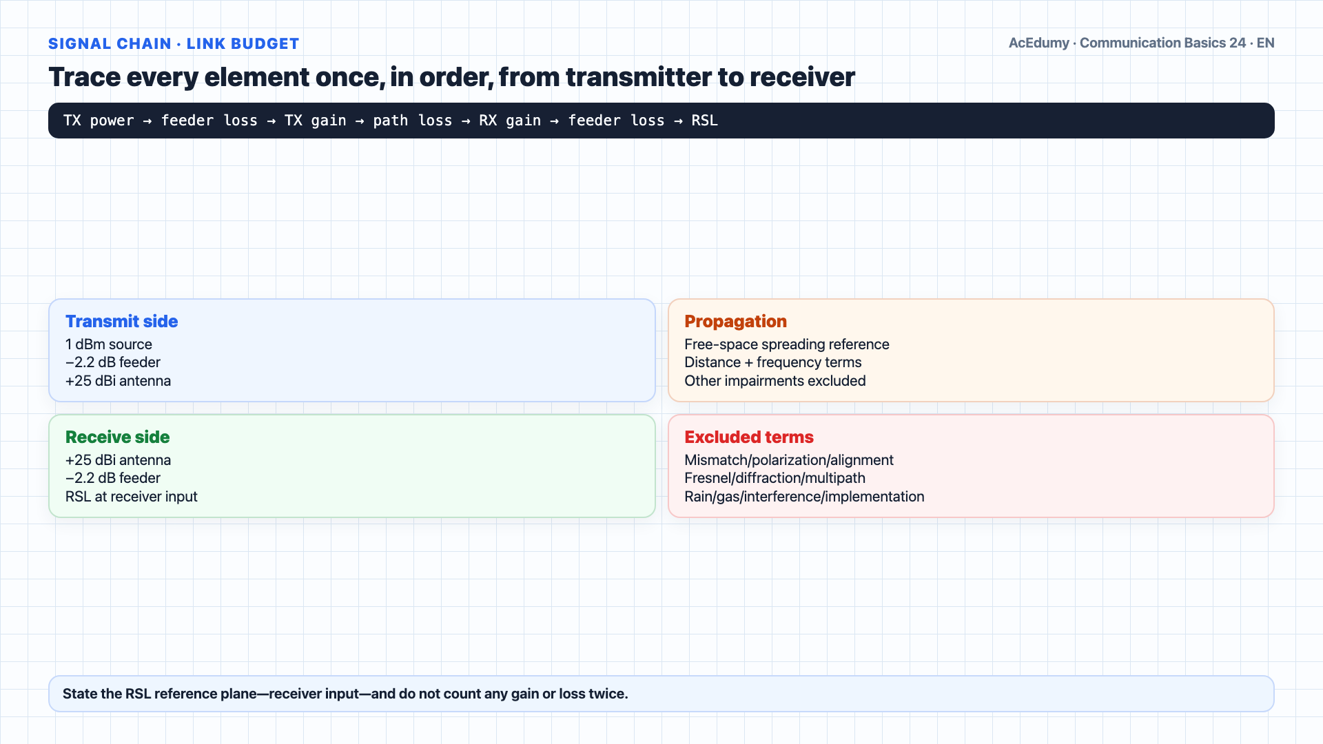
Verify the free-space arithmetic, but do not generalize band or fade-margin decisions independently of spectrum, antenna, propagation, threshold, and availability conditions. Before we crunch numbers, let us understand a link budget.Think of every element in the path as a dollar in or a dollar out of a bank account.The transmitter injects power.The cable at the transmitter side takes some away.The transmitting antenna adds directional gain.The free space path takes a huge amount — this is Free Space Loss, FSL.The receiving antenna adds more gain.The receiving cable takes some more away.What is left is the received signal level at the receiver.For a fixed isotropic reference, free-space basic transmission loss grows as 20log10(distance) and 20log10(frequency).FSL in decibels equals ninety six point six, plus twenty log of distance in miles, plus twenty log of frequency in gigahertz.Lower frequency, lower loss.Longer distance, higher loss.Narration transcript
Before we crunch numbers, let us understand a link budget. Think of every element in the path as a dollar in or a dollar out of a bank account. The transmitter injects power. The cable at the transmitter side takes some away. The transmitting antenna adds directional gain. The free space path takes a huge amount — this is Free Space Loss, F S L. The receiving antenna adds more gain. The receiving cable takes some more away. What is left is the received signal level at the receiver. The key insight is that free space loss grows with both distance and frequency. F S L in decibels equals ninety six point six, plus twenty log of distance in miles, plus twenty log of frequency in gigahertz. Lower frequency, lower loss. Longer distance, higher loss.
5. Compare range and bandwidth choices as conditional trade-offs
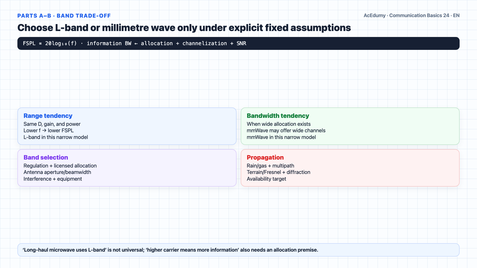
Verify the free-space arithmetic, but do not generalize band or fade-margin decisions independently of spectrum, antenna, propagation, threshold, and availability conditions. Parts a and b.These are band trade-off questions.For the longest possible link, we want the lowest free space loss.FSL scales with frequency, so we want the lowest frequency band.Among L-band, C-band, and millimeter wave, L-band wins.Lower frequency gives less FSPL only when other link-budget terms are fixed; real long-haul band selection also depends on regulation, bandwidth, antenna aperture/gain, interference, and propagation.For the highest information bandwidth, we want the widest available spectrum.Wider channel allocations may be available in higher bands; information bandwidth comes from regulation and channelization, not carrier frequency alone.Among the stated options, millimetre wave may offer the widest contiguous channel when allocation and link budget permit; this is a conditional spectrum-availability result.Narration transcript
Parts a and b. These are band trade-off questions. For the longest possible link, we want the lowest free space loss. F S L scales with frequency, so we want the lowest frequency band. Among L-band, C-band, and millimeter wave, L-band wins. That is why long range microwave links use the L-band. For the highest information bandwidth, we want the widest available spectrum. Higher frequency bands have more room for wide channels. Among our three, millimeter wave wins — it offers the widest contiguous spectrum for high capacity links like five G and beyond.
6. Calculate 96.6-dB free-space loss at one mile and 1 GHz
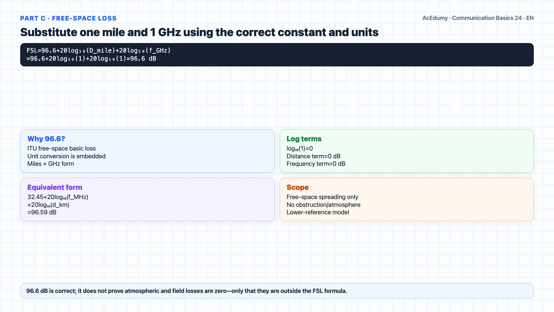
Verify the free-space arithmetic, but do not generalize band or fade-margin decisions independently of spectrum, antenna, propagation, threshold, and availability conditions. Part c, step one: compute the free space loss.FSL equals ninety six point six, plus twenty log of D, plus twenty log of F.Substitute D equals one mile, F equals one gigahertz.The log of one is zero, in both terms.So twenty log of one plus twenty log of one equals zero.FSL equals ninety six point six decibels.This is the loss the signal takes just from spreading out through space over one mile at one gigahertz.96.6 dB is only free-space spreading loss; separately budget terrain/obstruction, Fresnel clearance, diffraction, gas, rain, multipath, and implementation losses.Narration transcript
Part c, step one: compute the free space loss. F S L equals ninety six point six, plus twenty log of D, plus twenty log of F. Substitute D equals one mile, F equals one gigahertz. The log of one is zero, in both terms. So twenty log of one plus twenty log of one equals zero. F S L equals ninety six point six decibels. This is the loss the signal takes just from spreading out through space over one mile at one gigahertz. No obstacles, no atmosphere, just geometry.
7. Calculate −50-dBm received signal level with sign checks
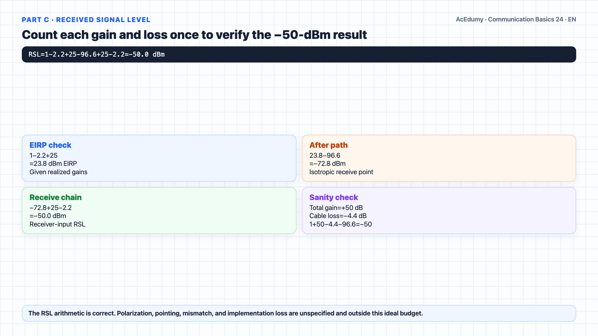
Verify the free-space arithmetic, but do not generalize band or fade-margin decisions independently of spectrum, antenna, propagation, threshold, and availability conditions. Part c, step two: compute the received signal level.The link budget equation is: RSL equals P o, minus the transmit cable loss, plus the transmit antenna gain, minus the receive cable loss, plus the receive antenna gain, minus FSL.Plug in our numbers.P o is plus one decibel milliwatt.Minus two point two decibels of cable loss.Plus twenty five decibel isotropic transmit gain.Minus two point two decibels of cable loss on the receiver side.Plus twenty five decibel isotropic receive gain.Minus ninety six point six decibels of free space loss.Add it all up: one minus two point two plus twenty five minus two point two plus twenty five minus ninety six point six equals negative fifty decibel milliwatt.That is the signal power arriving at the receiver.Narration transcript
Part c, step two: compute the received signal level. The link budget equation is: R S L equals P o, minus the transmit cable loss, plus the transmit antenna gain, minus the receive cable loss, plus the receive antenna gain, minus F S L. Plug in our numbers. P o is plus one decibel milliwatt. Minus two point two decibels of cable loss. Plus twenty five decibel isotropic transmit gain. Minus two point two decibels of cable loss on the receiver side. Plus twenty five decibel isotropic receive gain. Minus ninety six point six decibels of free space loss. Add it all up: one minus two point two plus twenty five minus two point two plus twenty five minus ninety six point six equals negative fifty decibel milliwatt. That is the signal power arriving at the receiver.
8. Derive 20-dB fade margin from −70 dBm and correct the c/d claim
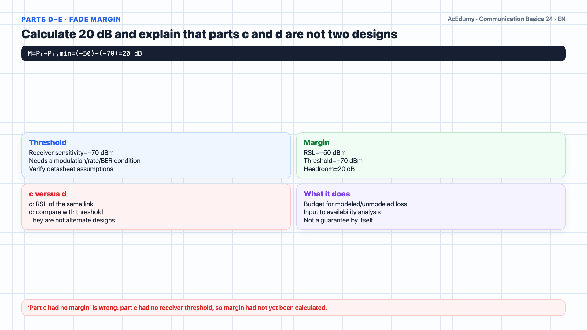
Verify the free-space arithmetic, but do not generalize band or fade-margin decisions independently of spectrum, antenna, propagation, threshold, and availability conditions. Part d: compute the fade margin.Fade margin is simply how much extra signal you have above the receiver's minimum sensitivity.It equals RSL minus the sensitivity threshold.The receiver sensitivity threshold is given as negative seventy decibel milliwatt.So fade margin equals negative fifty minus negative seventy equals twenty decibels.20 dB is total margin against the stated threshold; model rain, gas, multipath, and implementation losses separately and combine them against an availability objective.Part e asks which is better.Parts c and d are not alternate designs: c computes this link's RSL, while d compares that RSL with the −70-dBm receiver threshold to obtain 20-dB margin.Part c supplied no receiver threshold, so it did not calculate margin; that does not mean the physical margin was zero.Required fade margin follows from target availability and site-specific propagation statistics; it is not one universal number.Narration transcript
Part d: compute the fade margin. Fade margin is simply how much extra signal you have above the receiver's minimum sensitivity. It equals R S L minus the sensitivity threshold. The receiver sensitivity threshold is given as negative seventy decibel milliwatt. So fade margin equals negative fifty minus negative seventy equals twenty decibels. This twenty decibels is your cushion against rain, atmospheric absorption, and other fading effects. Part e asks which is better. The answer: Part d is better, because it has a twenty decibel margin. Part c had no margin — any small fade would drop the signal below threshold. In microwave engineering, fade margin is essential for link reliability.
9. Replace a universal margin with propagation and availability gates
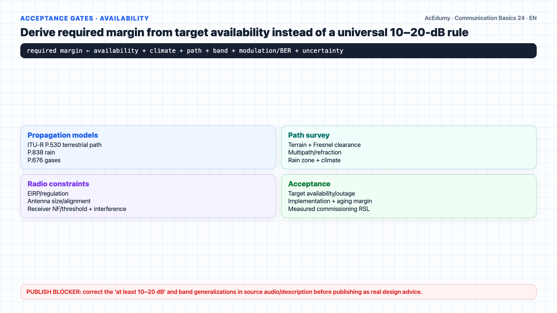
Verify the free-space arithmetic, but do not generalize band or fade-margin decisions independently of spectrum, antenna, propagation, threshold, and availability conditions. The big picture.Every microwave link budget has the same shape.Start with transmit power.Subtract cable loss.Add antenna gain.FSL is often a large terrestrial-link term; the dominant impairment depends on band, path, terrain, weather, antennas, and interference.Add receive antenna gain.Subtract receive cable loss.That gives you RSL.Then compare to receiver sensitivity.The difference is your fade margin.Three takeaways.One: FSL grows with distance and frequency — it dominates the link budget.Design levers include antenna gain/alignment, feeder loss, transmit power/EIRP limits, frequency, bandwidth, modulation/coding, receiver performance, route, and diversity.Derive fade margin from the availability objective, rain/gas/multipath models, climate, frequency, path length, receiver threshold, and implementation uncertainty; 10–20 dB is not a universal minimum.Good luck on your midterm.Narration transcript
The big picture. Every microwave link budget has the same shape. Start with transmit power. Subtract cable loss. Add antenna gain. Subtract free space loss — this is almost always the dominant term. Add receive antenna gain. Subtract receive cable loss. That gives you R S L. Then compare to receiver sensitivity. The difference is your fade margin. Three takeaways. One: F S L grows with distance and frequency — it dominates the link budget. Two: antenna gain and low cable loss are the main design levers you control. Three: always design with fade margin — at least ten to twenty decibels — to handle real-world atmospheric effects. Good luck on your midterm.
Source video: Communication Basics #24 Worked Example: Microwave Link Budget (9:12)