Communication Basics · Microwave Link Feasibility: LINK-1 versus LINK-2
#25 derive a 10-mile LINK-2 distance from equal 116.6-dB free-space loss for a 10-GHz/one-mile LINK-1 and 1-GHz LINK-2, calculate −70-dBm LINK-1 RSL and 8-dBm transmit power for a −72.6-dBm LINK-2 target, compare +20-dB and −12.6-dB margins, and correct the ideal threshold distance to 2.344 miles
Build equal 116.6-dB FSL for two microwave links, verify −70-dBm RSL and 8-dBm transmitter output, compare margin signs, and bound the incorrect 2.5-mile fix with the exact 2.344-mile ideal result.
Question
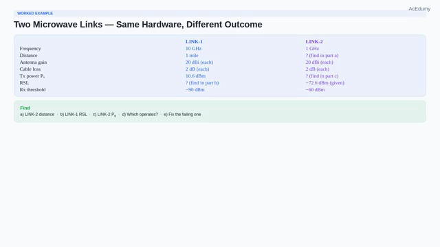
Separate the two links' reference planes, gains, losses, receiver thresholds, and target RSL; use FSL=96.6+20log10(d_mile)+20log10(f_GHz) to show 116.6 dB for 10 GHz×1 mile and 1 GHz×10 miles; calculate LINK-1 RSL=10.6−2+20−116.6+20−2=−70 dBm and LINK-2 Ptx=−72.6+2−20+116.6−20+2=8 dBm≈6.31 mW; derive margins of +20 dB and −12.6 dB; give the ideal free-space distance solution 10/10^(12.6/20)=2.344 miles and show that 2.5 miles remains about 0.559 dB short; add receiver-mode, EIRP, terrain/Fresnel, rain/gas/multipath, interference, and availability gates.
Written solution and narration transcript(shows the full solution)
Below are all the lines written in the notebook together with the full narration transcript.
1. Fix the two ideal links' inputs, reference planes, and receiver gates
Verify the ideal free-space arithmetic without treating equal path loss as equal feasibility or accepting the 2.5-mile estimate independently of receiver and availability targets. Welcome back.This is our seventh midterm prep video.Today we have two microwave links and we want to figure out which one will actually work.Here is the setup.Link one operates at ten gigahertz over a one mile distance.Link two operates at one gigahertz, but its distance is unknown — we have to find it.The exercise assumes Gt=Gr=20 dBi realized gain in both bands and 2-dB feeder loss at each end; this does not establish identical physical antenna hardware.We have five parts to solve.Part a: find the distance of link two such that its free space loss equals link one's.Part b: if link one's transmitter outputs ten point six dBm, find the link one RSL.Part c: if link two's RSL is negative seventy two point six dBm, find link two's required transmit power.Part d: receiver thresholds are negative ninety dBm for link one and negative sixty dBm for link two.Which link can operate?Part e: for the failing link, what can we do to make it work?Narration transcript
Welcome back. This is our seventh midterm prep video. Today we have two microwave links and we want to figure out which one will actually work. Here is the setup. Link one operates at ten gigahertz over a one mile distance. Link two operates at one gigahertz, but its distance is unknown — we have to find it. Both links use the same antennas with twenty d B i gain at each end, and the same cabling with two decibels of loss at each end. We have five parts to solve. Part a: find the distance of link two such that its free space loss equals link one's. Part b: if link one's transmitter outputs ten point six d B m, find the link one R S L. Part c: if link two's R S L is negative seventy two point six d B m, find link two's required transmit power. Part d: receiver thresholds are negative ninety d B m for link one and negative sixty d B m for link two. Which link can operate? Part e: for the failing link, what can we do to make it work?
2. Build link-budget bookkeeping with dB, dBm, and dBi references

Verify the ideal free-space arithmetic without treating equal path loss as equal feasibility or accepting the 2.5-mile estimate independently of receiver and availability targets. Quick dB recap before we dive in — same as last video.dB is 10log10 of a positive power ratio; it is dimensionless and needs an explicit gain/loss direction.dBm is the absolute power level PdBm=10log10(P/1 mW).dBi is the logarithmic antenna-gain ratio in a stated direction relative to an isotropic radiator; it is not absolute power.And the magic that makes link budgets simple: logarithms turn multiplication into addition.So in the dB world, transmit power, gains and losses just add and subtract.dBm minus dB plus dBi minus dB plus dBi minus dB equals dBm.The result is in dBm only when every dB gain/loss sign and isotropic/reference-plane definition is consistent.Now let us solve.Narration transcript
Quick d B recap before we dive in — same as last video. d B is a ratio: ten log of a power ratio. d B m is absolute power, d B above one milliwatt. d B i is antenna gain referenced to an isotropic radiator. And the magic that makes link budgets simple: logarithms turn multiplication into addition. So in the d B world, transmit power, gains and losses just add and subtract. d B m minus d B plus d B i minus d B plus d B i minus d B equals d B m. Units always collapse to d B m at the end. Now let us solve.
3. Find a 10-mile LINK-2 distance for equal 116.6-dB FSL
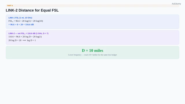
Verify the ideal free-space arithmetic without treating equal path loss as equal feasibility or accepting the 2.5-mile estimate independently of receiver and availability targets. Part a: find link two's distance such that both links have the same free space loss.Recall the FSL formula: ninety six point six plus twenty log of distance in miles plus twenty log of frequency in gigahertz.For link one at one mile and ten gigahertz: ninety six point six plus twenty log of one plus twenty log of ten equals ninety six point six plus zero plus twenty equals one hundred sixteen point six dB.For link two we want the same one hundred sixteen point six dB, but with frequency one gigahertz.One hundred sixteen point six equals ninety six point six plus twenty log D plus twenty log of one.Twenty log of one is zero.So twenty log D equals twenty, meaning log D equals one.Therefore D equals ten miles.Link two reaches ten miles at one gigahertz with the same loss link one has at one mile and ten gigahertz.With fixed isotropic gain and other budget terms, lower frequency permits greater distance at the same free-space loss; evaluate real-path conditions separately.Narration transcript
Part a: find link two's distance such that both links have the same free space loss. Recall the F S L formula: ninety six point six plus twenty log of distance in miles plus twenty log of frequency in gigahertz. For link one at one mile and ten gigahertz: ninety six point six plus twenty log of one plus twenty log of ten equals ninety six point six plus zero plus twenty equals one hundred sixteen point six d B. For link two we want the same one hundred sixteen point six d B, but with frequency one gigahertz. One hundred sixteen point six equals ninety six point six plus twenty log D plus twenty log of one. Twenty log of one is zero. So twenty log D equals twenty, meaning log D equals one. Therefore D equals ten miles. Link two reaches ten miles at one gigahertz with the same loss link one has at one mile and ten gigahertz. Lower frequency lets you go farther for the same loss budget.
4. Calculate LINK-1 received signal level as −70 dBm
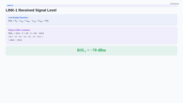
Verify the ideal free-space arithmetic without treating equal path loss as equal feasibility or accepting the 2.5-mile estimate independently of receiver and availability targets. Part b: find link one's received signal level.We use the link budget equation.RSL equals transmit power minus transmit cable loss plus transmit antenna gain minus receive cable loss plus receive antenna gain minus FSL.Plug in link one's numbers.Transmit power is ten point six dBm.Minus two dB cable, plus twenty dBi antenna, minus two dB cable, plus twenty dBi antenna, minus one hundred sixteen point six dB FSL.Add it all up: ten point six minus two plus twenty minus two plus twenty minus one hundred sixteen point six equals negative seventy dBm.Link one's RSL is negative seventy dBm at the receiver.Narration transcript
Part b: find link one's received signal level. We use the link budget equation. R S L equals transmit power minus transmit cable loss plus transmit antenna gain minus receive cable loss plus receive antenna gain minus F S L. Plug in link one's numbers. Transmit power is ten point six d B m. Minus two d B cable, plus twenty d B i antenna, minus two d B cable, plus twenty d B i antenna, minus one hundred sixteen point six d B F S L. Add it all up: ten point six minus two plus twenty minus two plus twenty minus one hundred sixteen point six equals negative seventy d B m. Link one's R S L is negative seventy d B m at the receiver.
5. Solve backward for 8-dBm LINK-2 transmit power
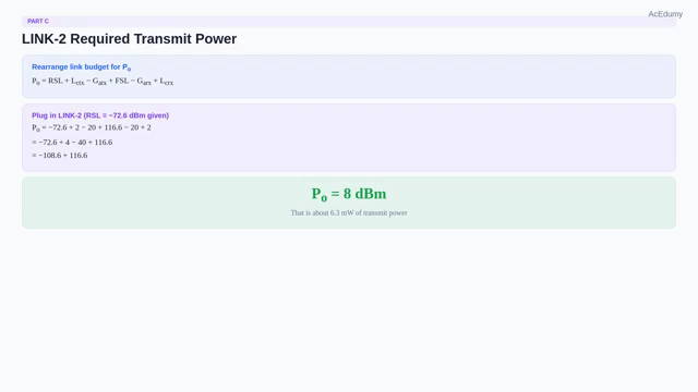
Verify the ideal free-space arithmetic without treating equal path loss as equal feasibility or accepting the 2.5-mile estimate independently of receiver and availability targets. Part c: find link two's required transmit power, given that its RSL must be negative seventy two point six dBm.We rearrange the link budget equation to solve for transmit power.Transmit power equals RSL plus transmit cable loss minus transmit gain plus FSL minus receive gain plus receive cable loss.Plug in: negative seventy two point six plus two minus twenty plus one hundred sixteen point six minus twenty plus two.Compute: negative seventy two point six plus four equals negative sixty eight point six.Minus forty equals negative one hundred eight point six.Plus one hundred sixteen point six equals eight dBm.Link two needs eight dBm of transmit power to deliver negative seventy two point six dBm at the receiver.That is about six point three milliwatts.Narration transcript
Part c: find link two's required transmit power, given that its R S L must be negative seventy two point six d B m. We rearrange the link budget equation to solve for transmit power. Transmit power equals R S L plus transmit cable loss minus transmit gain plus F S L minus receive gain plus receive cable loss. Plug in: negative seventy two point six plus two minus twenty plus one hundred sixteen point six minus twenty plus two. Compute: negative seventy two point six plus four equals negative sixty eight point six. Minus forty equals negative one hundred eight point six. Plus one hundred sixteen point six equals eight d B m. Link two needs eight d B m of transmit power to deliver negative seventy two point six d B m at the receiver. That is about six point three milliwatts.
6. Calculate +20/−12.6-dB margins and the exact 2.344-mile fix
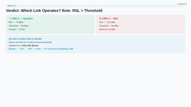
Verify the ideal free-space arithmetic without treating equal path loss as equal feasibility or accepting the 2.5-mile estimate independently of receiver and availability targets. Part d: which link can actually operate?The ideal raw gate is RSL≥receiver threshold for a specified modulation/rate/BER; field acceptance also needs required fade margin and availability.If RSL exceeds threshold, raw link margin is positive; that alone does not guarantee field availability.If RSL is below threshold, the stated receiver mode is unsupported in the ideal budget.Link one: RSL is negative seventy dBm, threshold is negative ninety dBm.Negative seventy is greater than negative ninety, so link one operates with twenty dB of margin.Link two: RSL is negative seventy two point six dBm, threshold is negative sixty dBm.Negative seventy two point six is less than negative sixty, so link two cannot operate as designed.The signal is too weak by twelve point six dB.Part e: what can we do to fix link two?We need to either increase RSL or relax the threshold.With receiver mode fixed, reducing distance is one option; also assess power/EIRP, antenna/alignment, feeder loss, robust mode, relay, and diversity within constraints.Shorter distance means lower FSL, which directly raises RSL.Closing the 12.6-dB deficit by free-space distance alone requires 10/10(12.6/20)=2.344 miles; 2.5 miles gains only 12.041 dB and remains about 0.559 dB short.Narration transcript
Part d: which link can actually operate? The rule is simple: the received signal level must exceed the receiver sensitivity threshold. If R S L is greater than threshold, the link works. If less, it fails. Link one: R S L is negative seventy d B m, threshold is negative ninety d B m. Negative seventy is greater than negative ninety, so link one operates with twenty d B of margin. Link two: R S L is negative seventy two point six d B m, threshold is negative sixty d B m. Negative seventy two point six is less than negative sixty, so link two cannot operate as designed. The signal is too weak by twelve point six d B. Part e: what can we do to fix link two? We need to either increase R S L or relax the threshold. Since the receiver is fixed, the practical fix is to reduce the link distance. Shorter distance means lower F S L, which directly raises R S L. Cutting the distance from ten miles down to about two and a half miles would gain us the missing twelve d B and put the link back in the operating zone.
7. Add field and availability gates to the threshold comparison
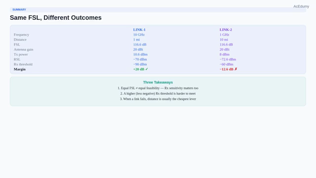
Verify the ideal free-space arithmetic without treating equal path loss as equal feasibility or accepting the 2.5-mile estimate independently of receiver and availability targets. Big picture comparison.The ideal model gives both links 116.6-dB FSL and the same numerical 20-dBi gain assumption; it does not imply identical physical antennas or feasibility.LINK-1 has −70−(−90)=+20 dB raw margin; a ‘healthy’ acceptance still requires receiver-mode, interference, propagation, and availability checks.Link two delivers an RSL of negative seventy two point six dBm, but its threshold is much higher at negative sixty dBm.It fails by twelve point six dB.Three takeaways.One: equal FSL does not mean equal feasibility; receiver threshold for the chosen modulation/rate/BER is one link-budget term.Two: a higher receiver threshold is harder to satisfy than a lower one.Three: the lowest-cost fix is site-specific; moving endpoints or rerouting may be costly or impossible, while power/antenna permits depend on jurisdiction and EIRP rules.And that wraps up our midterm prep batch.Good luck on your midterm.Narration transcript
Big picture comparison. Both links share the same F S L of one hundred sixteen point six d B and the same antennas. Link one delivers an R S L of negative seventy d B m, well above its negative ninety d B m threshold — twenty d B of fade margin, a healthy link. Link two delivers an R S L of negative seventy two point six d B m, but its threshold is much higher at negative sixty d B m. It fails by twelve point six d B. Three takeaways. One: equal F S L does not mean equal feasibility — receiver sensitivity matters as much as transmit budget. Two: a higher receiver threshold is harder to satisfy than a lower one. Three: when a link fails, the cheapest fix is usually distance — everything else like bigger antennas or more power costs more money and more permits. And that wraps up our midterm prep batch. Good luck on your midterm.
Source video: Communication Basics #25 Worked Example: Microwave Link Feasibility (LINK-1 vs LINK-2) (7:46)