Communication Basics · Microwave System Design
#10 LOS and Fresnel clearance, free-space loss, link budget, receiver threshold, fade margin, and ITU-R availability scope
Move microwave design beyond frequency/reach rules of thumb and through LOS, Fresnel, link-budget, threshold, and statistical-availability gates.
Question
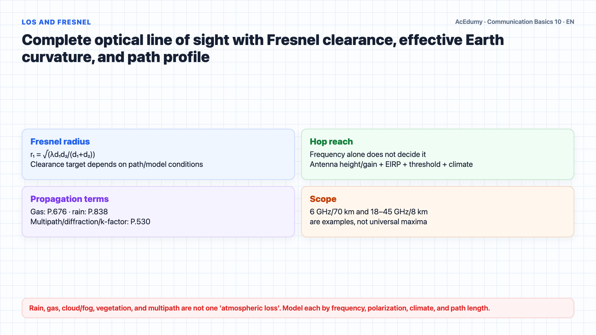
Build the microwave link with LOS/Fresnel geometry; audit FSPL units; compute received power with all gains and losses; connect fade margin to ITU-R propagation models instead of treating it as an availability percentage by itself.
Written solution and narration transcript(shows the full solution)
Below are all the lines written in the notebook together with the full narration transcript.
1. Build LOS, Fresnel clearance, and frequency-dependent losses
The microwave link is audited with free-space loss, all gains/losses, Fresnel clearance, and a statistical propagation model. There is no universal 1–45 GHz microwave boundary; context may use roughly 300 MHz/1 GHz–300 GHz, while terrestrial fixed-service bands follow regulation.These are generally point to point links where a transmitter focuses a narrow radio beam toward a distant receiver.Line of sight is critical.Optical LOS alone is insufficient: first-Fresnel-zone clearance, Earth curvature/effective k-factor, terrain, vegetation, and diffraction must be checked together.Hop reach is not a function of frequency alone; antenna height/gain, EIRP, receiver threshold, Fresnel clearance, spectrum rules, climate, rain, and target availability all matter.Seventy kilometres at 6 GHz is one possible design example, not a universal maximum; path/Fresnel profile, link budget, and ITU-R P.530 availability must pass.Eight kilometres at 18/45 GHz is not universal. Evaluate FSPL, physical antenna aperture, rain (P.838), gaseous attenuation (P.676), and regulated EIRP together.Rain, gases, cloud/fog, vegetation, and multipath use separate ITU-R models; magnitude depends on frequency, polarization, rainfall/climate, and path length. 'Smog' is not a generic fixed loss.Despite these challenges, microwave links remain essential today for telecom backbone connections and increasingly for 5G mobile backhaul, where millimeter wave frequencies at 28 and 39 gigahertz use the same fundamental principles we are about to study.Narration transcript
Microwave communication uses free space radio links operating from UHF through EHF, practically from about 1 gigahertz up to 45 gigahertz. These are generally point to point links where a transmitter focuses a narrow radio beam toward a distant receiver. Line of sight is critical. Physical obstacles like trees, buildings, and mountains must be avoided, and the Earth's curvature limits the maximum distance between towers. The hopping distance, meaning the maximum distance between two towers, depends on the carrier frequency. At lower frequencies like 6 gigahertz, hops can reach about 70 kilometers. At higher frequencies like 18 or 45 gigahertz, hops shrink to around 8 kilometers because higher frequencies suffer more atmospheric absorption. Rain, fog, smog, and humidity all weaken microwave signals. Despite these challenges, microwave links remain essential today for telecom backbone connections and increasingly for 5G mobile backhaul, where millimeter wave frequencies at 28 and 39 gigahertz use the same fundamental principles we are about to study.
2. Build FSPL units and the complete link budget
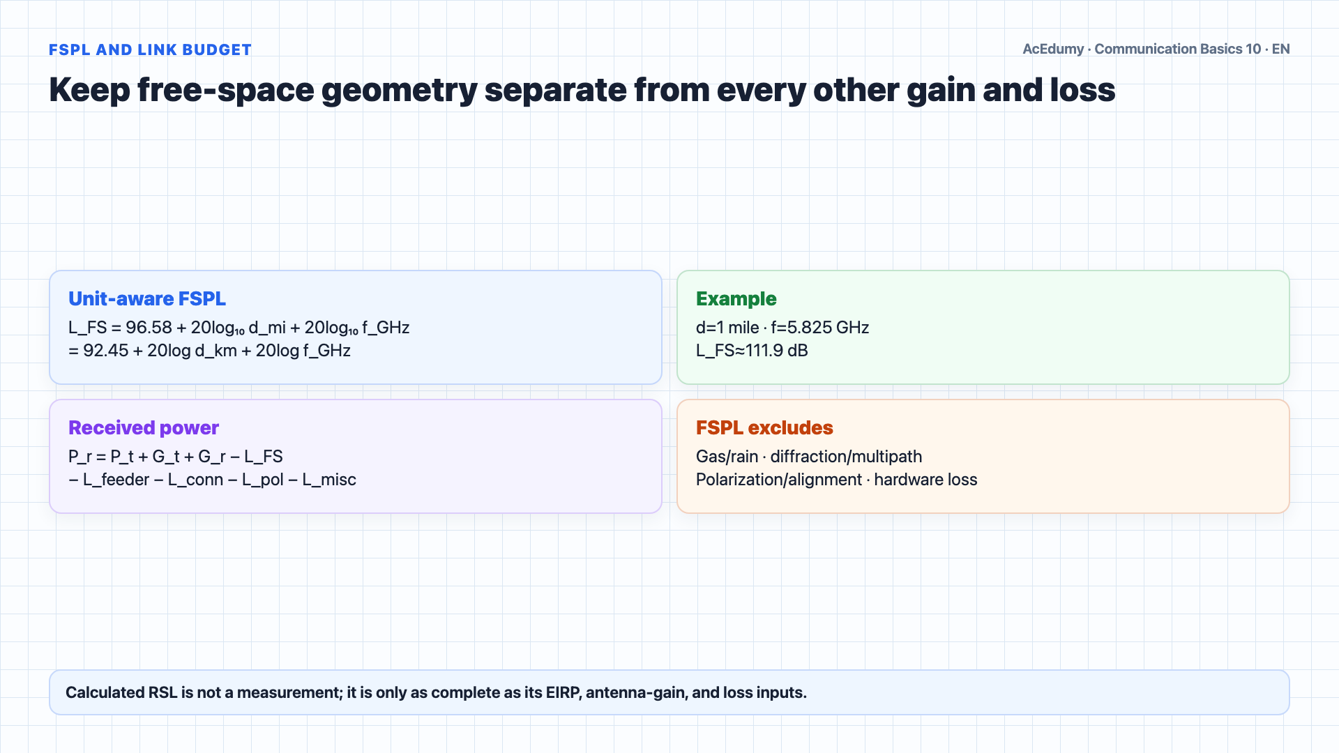
The microwave link is audited with free-space loss, all gains/losses, Fresnel clearance, and a statistical propagation model. The key formula in microwave design is Free Space Loss, or FSL.FSPL is ideal geometric spreading loss in free space; it excludes gaseous/rain attenuation, diffraction, multipath, polarization mismatch, and hardware losses.In decibels, FSL equals 96.6 plus 20 times the log of D plus 20 times the log of F, where D is the distance in miles and F is the frequency in gigahertz.For example, a 1 mile link at 5.825 gigahertz has an FSL of 96.6 plus 20 log of 1 plus 20 log of 5.825, which equals 96.6 plus 0 plus 15.3, giving 111.9 decibels.But FSL alone does not tell us if a link will work.We need the Received Signal Level, or RSL.RSL accounts for the complete link budget: the transmitter output power P sub o in dBm, minus cable losses at the transmitter and receiver, plus antenna gains at both ends, minus the Free Space Loss.The formula is: RSL equals P sub o minus L c t x plus G a t x minus L c r x plus G a r x minus FSL.Calculated RSL is only as complete as its EIRP, antenna gains, feeder/connectors, polarization, radome, miscellaneous, and propagation-loss inputs; it is not a measurement.Narration transcript
The key formula in microwave design is Free Space Loss, or FSL. FSL quantifies how much a signal weakens as it travels through open air. In decibels, FSL equals 96.6 plus 20 times the log of D plus 20 times the log of F, where D is the distance in miles and F is the frequency in gigahertz. For example, a 1 mile link at 5.825 gigahertz has an FSL of 96.6 plus 20 log of 1 plus 20 log of 5.825, which equals 96.6 plus 0 plus 15.3, giving 111.9 decibels. But FSL alone does not tell us if a link will work. We need the Received Signal Level, or RSL. RSL accounts for the complete link budget: the transmitter output power P sub o in dBm, minus cable losses at the transmitter and receiver, plus antenna gains at both ends, minus the Free Space Loss. The formula is: RSL equals P sub o minus L c t x plus G a t x minus L c r x plus G a r x minus FSL. RSL tells us the actual signal strength arriving at the receiver.
3. Separate receiver threshold, fade margin, and availability
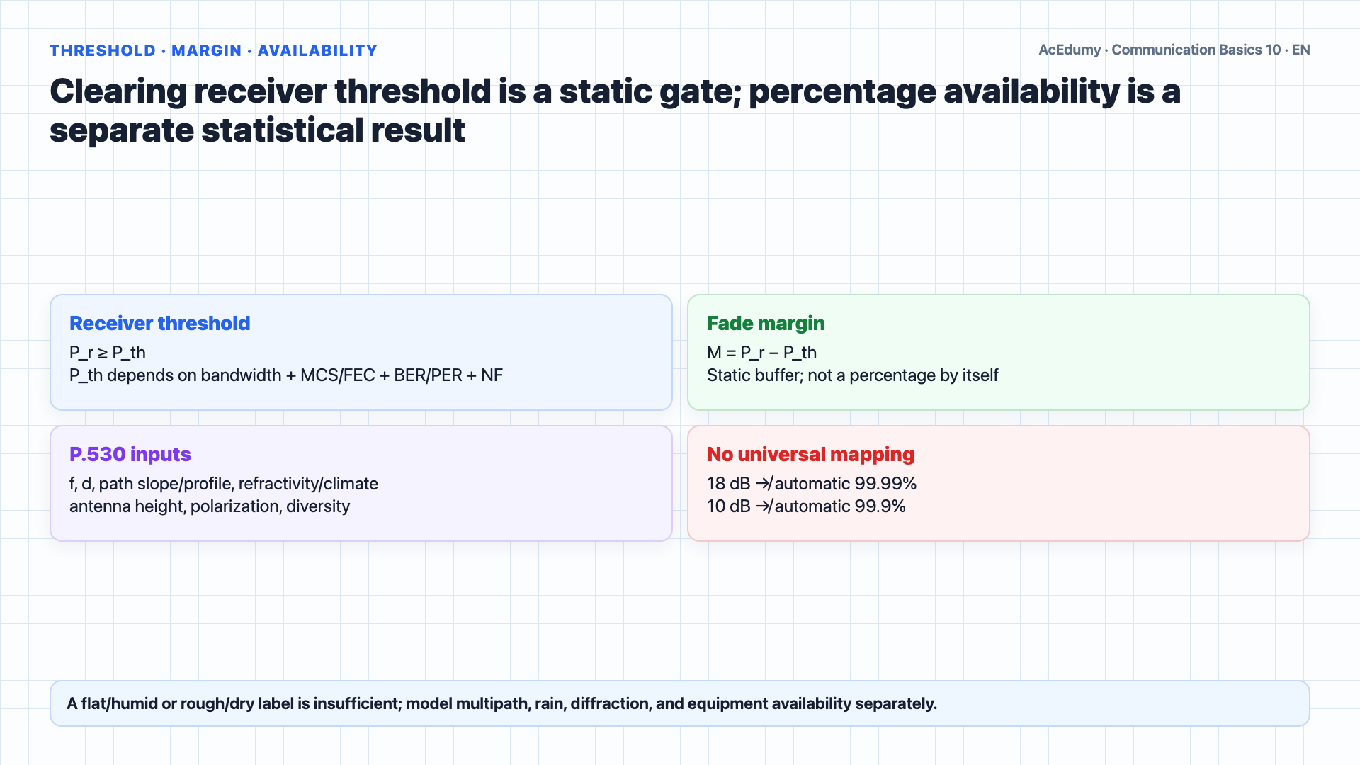
The microwave link is audited with free-space loss, all gains/losses, Fresnel clearance, and a statistical propagation model. Every receiver has a minimum signal strength it needs to work correctly.This is called the Receiver Sensitivity Threshold, or R sub x.A link is theoretically feasible if the Received Signal Level is greater than or equal to the Receiver Sensitivity Threshold.In other words, RSL must be greater than or equal to R sub x.But just barely meeting the threshold is not enough in practice.Path fading, caused by atmospheric conditions, can temporarily weaken the signal below normal levels.Fade Margin is the safety buffer between RSL and R sub x.Fade Margin equals RSL minus R sub x.A higher Fade Margin means the link can withstand more fading and therefore has higher availability.18 dB→99.99% and 10 dB→99.9% is not universal; ITU-R P.530 availability uses frequency, path, climate/refractivity, rain, polarization, antenna height, and diversity.Multipath and rain risk cannot be inferred from a terrain label alone; refractivity, path profile, water/coast, climate, frequency, and path inclination are inputs.Rough/dry terrain does not automatically ensure availability; diffraction/Fresnel blockage, multipath, gas/rain loss, and equipment reliability still require models.Narration transcript
Every receiver has a minimum signal strength it needs to work correctly. This is called the Receiver Sensitivity Threshold, or R sub x. A link is theoretically feasible if the Received Signal Level is greater than or equal to the Receiver Sensitivity Threshold. In other words, RSL must be greater than or equal to R sub x. But just barely meeting the threshold is not enough in practice. Path fading, caused by atmospheric conditions, can temporarily weaken the signal below normal levels. Fade Margin is the safety buffer between RSL and R sub x. Fade Margin equals RSL minus R sub x. A higher Fade Margin means the link can withstand more fading and therefore has higher availability. For example, a Fade Margin of 18 decibels might give 99.99 percent availability, while a Fade Margin of only 10 decibels might drop to 99.9 percent. In flat, humid environments fading is more severe, requiring larger Fade Margins. In rough, dry terrain, fading is less frequent.
4. Audit the 5.825 GHz / one-mile example and missing gates
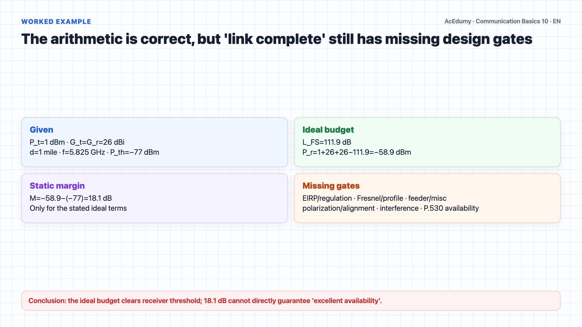
The microwave link is audited with free-space loss, all gains/losses, Fresnel clearance, and a statistical propagation model. Let us work through a complete link budget calculation step by step.Given: a 1 mile microwave link at 5.825 gigahertz.Transmitter output power is 1 dBm.Both antennas have a gain of 26 dBi.No cable losses for simplicity.Receiver Sensitivity Threshold is minus 77 dBm.Step 1: Calculate FSL.FSL equals 96.6 plus 20 log of 1 plus 20 log of 5.825.20 log of 1 equals 0.20 log of 5.825 equals 15.3.FSL equals 96.6 plus 0 plus 15.3 equals 111.9 decibels.Step 2: Calculate RSL.RSL equals 1 dBm plus 26 dBi plus 26 dBi minus 111.9 dB.RSL equals 53 minus 111.9 equals minus 58.9 dBm.Step 3: Check feasibility.RSL of minus 58.9 dBm is greater than R sub x of minus 77 dBm.The static ideal budget clears receiver threshold by 18.1 dB; regulatory EIRP, Fresnel clearance, alignment, polarization, feeder/misc losses, interference, and target availability still must pass.Step 4: Calculate Fade Margin.Fade Margin equals minus 58.9 minus the quantity minus 77 equals 18.1 decibels.18.1 dB is only this incomplete static budget's fade margin; by itself it guarantees neither 'excellent' performance nor a specific availability percentage.Narration transcript
Let us work through a complete link budget calculation step by step. Given: a 1 mile microwave link at 5.825 gigahertz. Transmitter output power is 1 dBm. Both antennas have a gain of 26 dBi. No cable losses for simplicity. Receiver Sensitivity Threshold is minus 77 dBm. Step 1: Calculate FSL. FSL equals 96.6 plus 20 log of 1 plus 20 log of 5.825. 20 log of 1 equals 0. 20 log of 5.825 equals 15.3. FSL equals 96.6 plus 0 plus 15.3 equals 111.9 decibels. Step 2: Calculate RSL. RSL equals 1 dBm plus 26 dBi plus 26 dBi minus 111.9 dB. RSL equals 53 minus 111.9 equals minus 58.9 dBm. Step 3: Check feasibility. RSL of minus 58.9 dBm is greater than R sub x of minus 77 dBm. The link is feasible. Step 4: Calculate Fade Margin. Fade Margin equals minus 58.9 minus the quantity minus 77 equals 18.1 decibels. This is a comfortable margin providing excellent link availability.
5. Summarize the microwave design gates
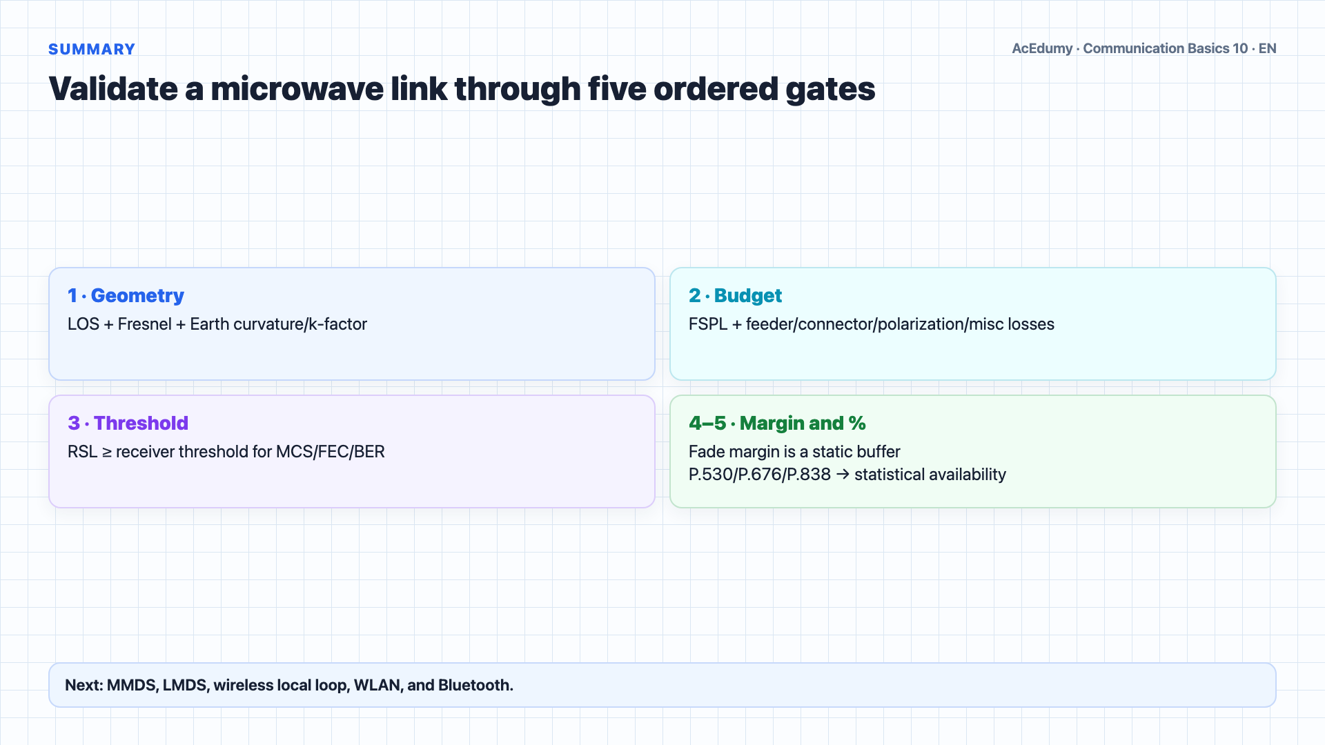
The microwave link is audited with free-space loss, all gains/losses, Fresnel clearance, and a statistical propagation model. Let us review.Terrestrial microwave links use multiple regulated bands; 1–45 GHz is not a universal boundary, and LOS plus Fresnel clearance are required.Higher frequency alone does not set reach; FSPL/antenna aperture, gas/rain, EIRP, Fresnel clearance, threshold, and target availability act together.Free Space Loss: FSL equals 96.6 plus 20 log D plus 20 log F in decibels.Received Signal Level: RSL equals transmitter power plus antenna gains minus cable losses minus FSL.A link is feasible when RSL is greater than or equal to the Receiver Sensitivity Threshold.Fade margin = RSL−threshold is a static buffer; availability comes from P.530/P.676/P.838 plus equipment/diversity models, not margin alone.These same principles apply to modern 5G millimeter wave backhaul.In the next lesson, we will cover wireless access technologies: MMDS, LMDS, Wireless Local Loop, WLAN, and Bluetooth.Narration transcript
Let us review. Microwave links operate from 1 to 45 gigahertz as point to point line of sight connections. Higher frequency means shorter hop distance due to atmospheric absorption. Free Space Loss: FSL equals 96.6 plus 20 log D plus 20 log F in decibels. Received Signal Level: RSL equals transmitter power plus antenna gains minus cable losses minus FSL. A link is feasible when RSL is greater than or equal to the Receiver Sensitivity Threshold. Fade Margin equals RSL minus R sub x and determines link availability against atmospheric fading. These same principles apply to modern 5G millimeter wave backhaul. In the next lesson, we will cover wireless access technologies: MMDS, LMDS, Wireless Local Loop, WLAN, and Bluetooth.
Source video: Communication Basics #10 Microwave System Design (7:05)