Antenna Theory · N-Element Linear Array, Beam Width, and Lobes
#12 The closed-form uniform linear array factor, 1/N beam narrowing, side lobes, grating lobes, and spacing constraints
Read beam narrowing, side lobes, and grating-lobe limits directly from the N-element closed-form array factor.
Question
Derive the array factor of N identical equally spaced elements from the geometric series; interpret how element count changes beam width and side lobes, and state the grating-lobe spacing conditions.
Written solution and narration transcript(shows the full solution)
Below are all the lines written in the notebook together with the full narration transcript.
1. Recall the two-element array factor and steering result
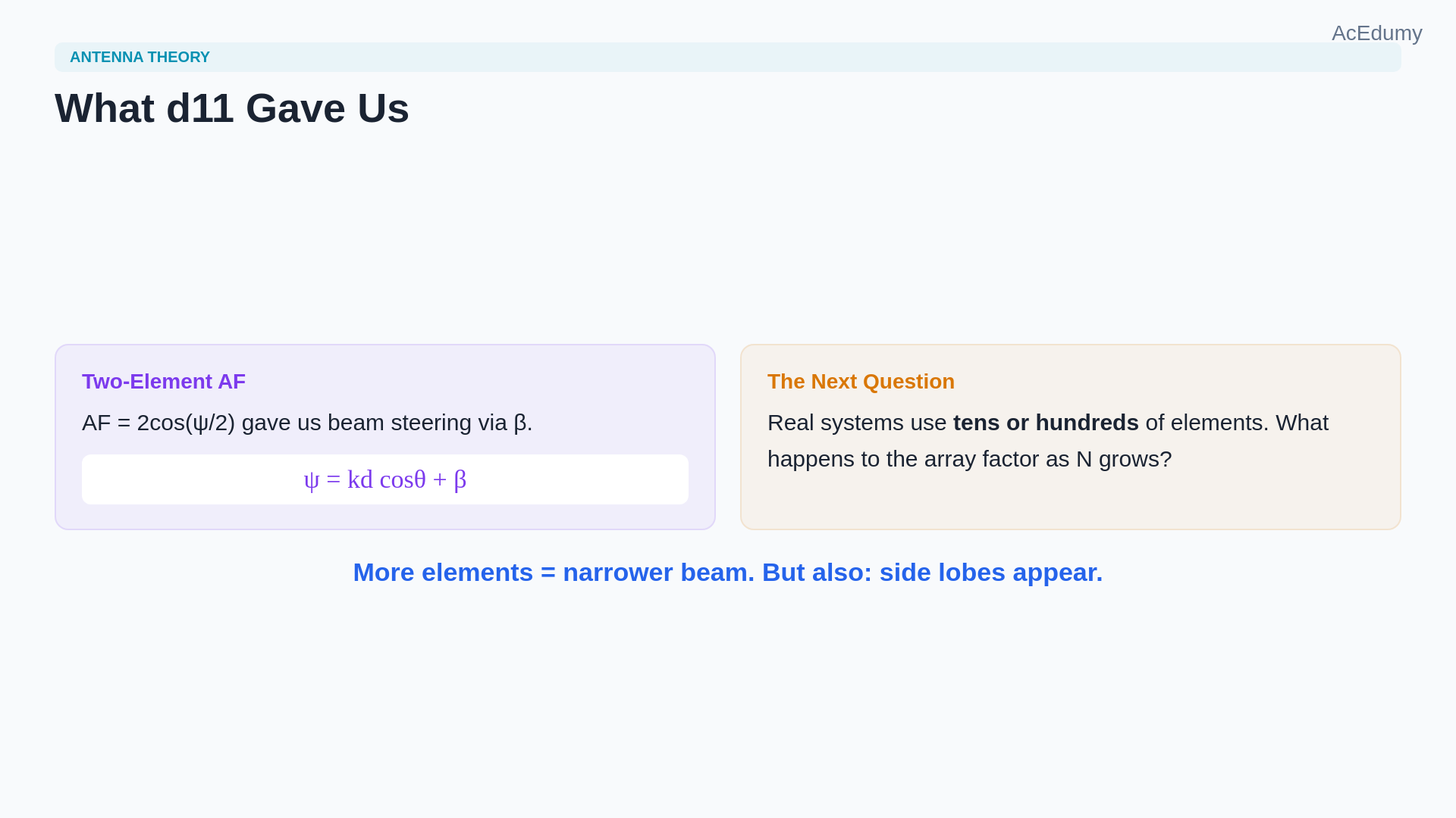
Element count narrows the main beam roughly as 1/N; amplitude taper controls side lobes and spacing controls grating lobes. In the last lesson we saw that two elements produce an array factor of 2cos(ψ/2), where ψ = kd cosθ + β.That simple factor already gave us beam steering.But real systems use many more elements.The natural question is: what happens to the array factor when we extend the same idea to N identical elements in a row?Narration transcript
In the last lesson we saw that two elements produce an array factor of two cosine of psi over two, where psi equals k d cosine theta plus beta. That simple factor already gave us beam steering. But real systems use many more elements. The natural question is: what happens to the array factor when we extend the same idea to N identical elements in a row?
2. Set up N equally spaced elements with progressive phase
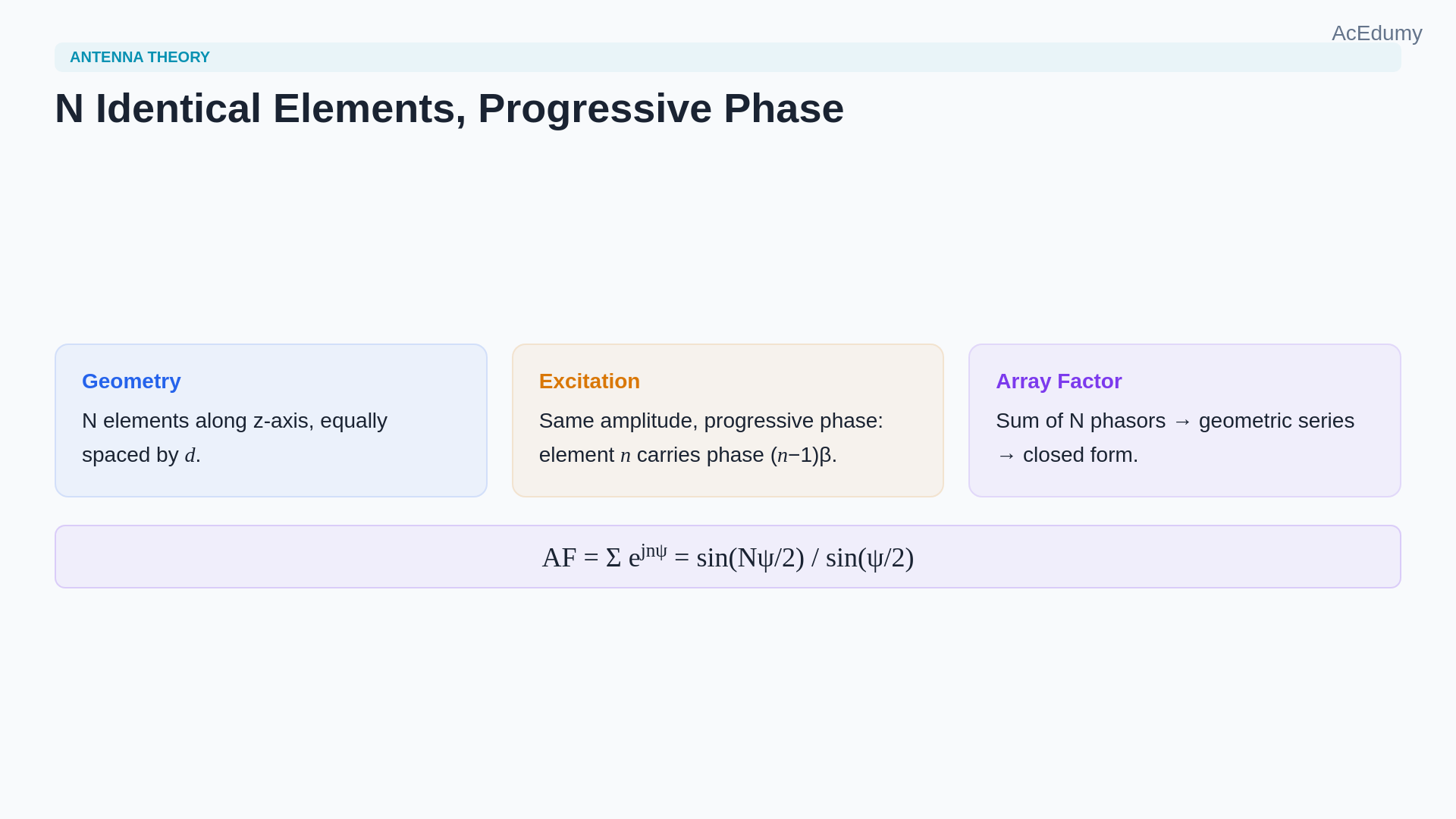
Element count narrows the main beam roughly as 1/N; amplitude taper controls side lobes and spacing controls grating lobes. Line up N identical elements along the z axis, equally spaced by distance d.Feed each element with the same amplitude but with a progressive phase shift: element number n carries a phase of (n−1)β.The total array factor is the sum of N phasors, each offset by ψ = kd cosθ + β.This geometric series has a well-known closed form.Narration transcript
Line up N identical elements along the z axis, equally spaced by distance d. Feed each element with the same amplitude but with a progressive phase shift: element number n carries a phase of n minus one times beta. The total array factor is the sum of N phasors, each offset by psi equals k d cosine theta plus beta. This geometric series has a well-known closed form.
3. Derive the sin(Nψ/2)/sin(ψ/2) closed form
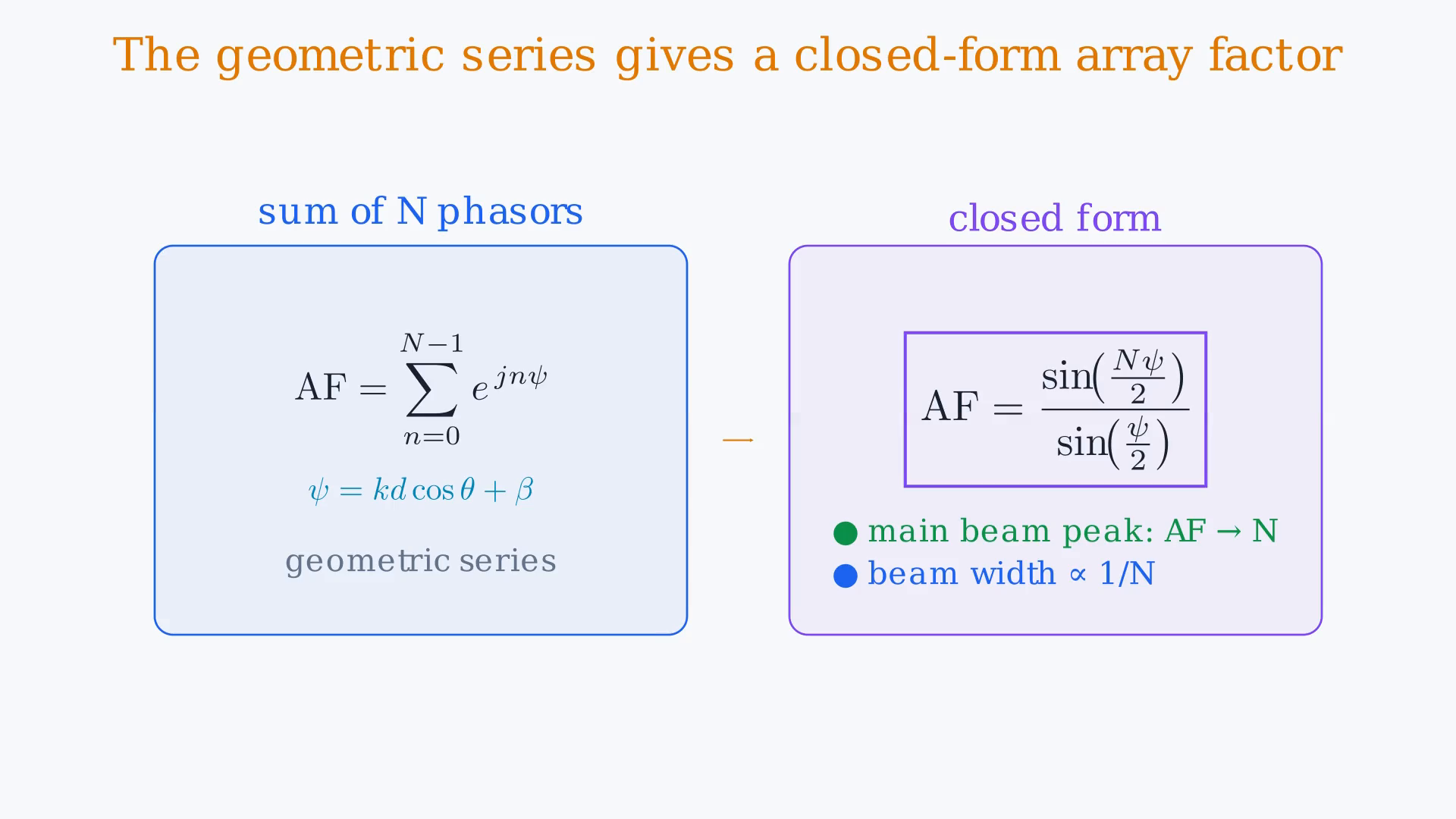
Element count narrows the main beam roughly as 1/N; amplitude taper controls side lobes and spacing controls grating lobes. Summing the geometric series gives the N-element array factor: sin(Nψ/2)/sin(ψ/2).When ψ approaches zero, both sine terms vanish and the ratio approaches N, which is the main beam peak.This single formula replaces the two-element cosine and carries all the beam-shaping information for any number of elements.Narration transcript
Summing the geometric series gives the N-element array factor: sine of N psi over two, divided by sine of psi over two. When psi approaches zero, both sine terms vanish and the ratio approaches N, which is the main beam peak. This single formula replaces the two-element cosine and carries all the beam-shaping information for any number of elements.
4. Compare beam narrowing for N=2, 4, and 8
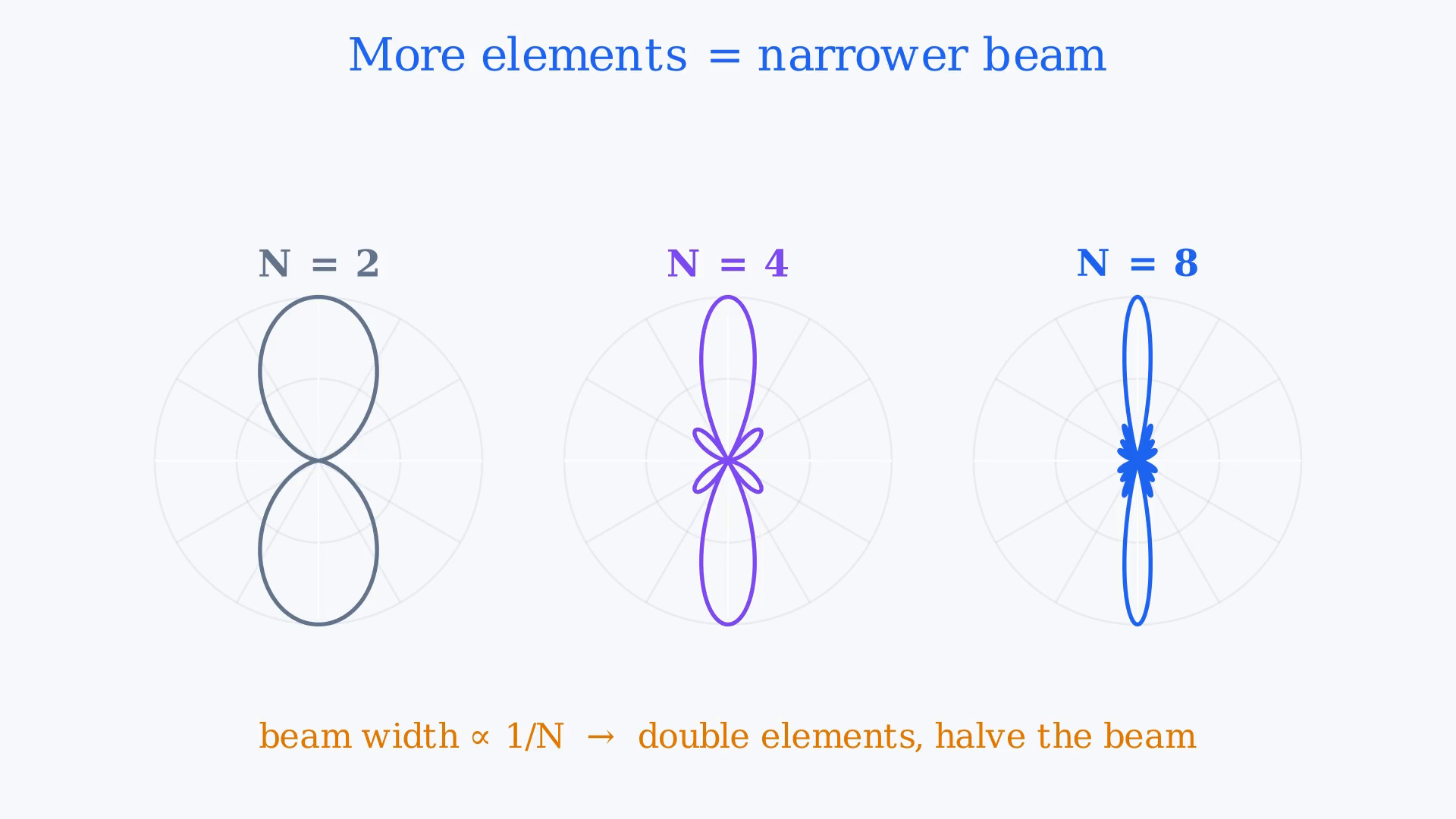
Element count narrows the main beam roughly as 1/N; amplitude taper controls side lobes and spacing controls grating lobes. Compare the array factor for two, four, and eight elements.With two elements the main lobe is broad.Double to four and the lobe narrows noticeably.Double again to eight and the beam becomes a sharp pencil.The half-power beam width shrinks roughly as 1/N, so doubling the number of elements halves the beam width.This is the fundamental trade-off: more elements mean a narrower beam, but also a larger and more expensive array.Narration transcript
Compare the array factor for two, four, and eight elements. With two elements the main lobe is broad. Double to four and the lobe narrows noticeably. Double again to eight and the beam becomes a sharp pencil. The half-power beam width shrinks roughly as one over N, so doubling the number of elements halves the beam width. This is the fundamental trade-off: more elements mean a narrower beam, but also a larger and more expensive array.
5. Interpret an eight-element broadside array in three dimensions
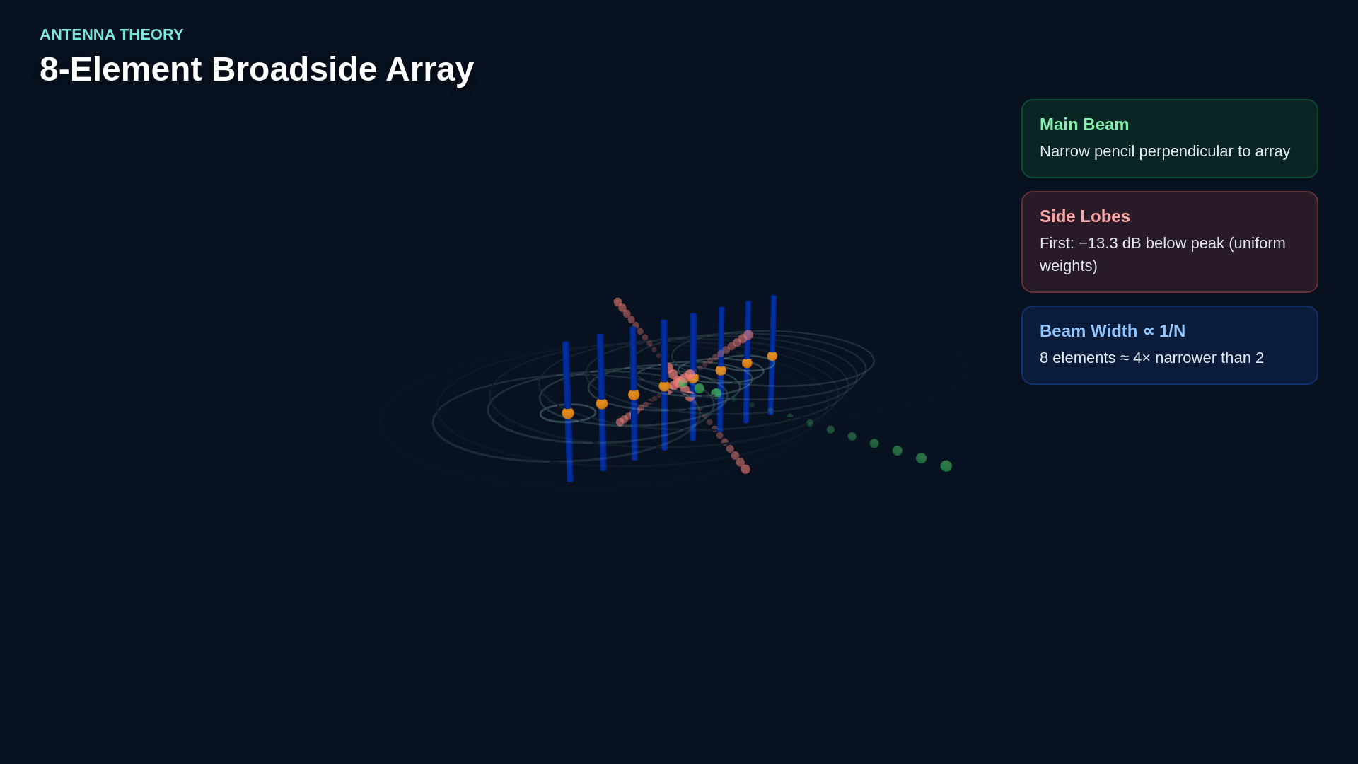
Element count narrows the main beam roughly as 1/N; amplitude taper controls side lobes and spacing controls grating lobes. In three dimensions an eight-element broadside array produces a narrow disc of radiation perpendicular to the array axis.The main beam is flanked by smaller side lobes.These side lobes are an unavoidable consequence of the finite array size.The first side lobe sits about 13.3 dB below the main beam peak for a uniformly weighted array.Reducing side lobes requires tapering the element amplitudes, which widens the main beam slightly — another classic engineering trade-off.Narration transcript
In three dimensions an eight-element broadside array produces a narrow disc of radiation perpendicular to the array axis. The main beam is flanked by smaller side lobes. These side lobes are an unavoidable consequence of the finite array size. The first side lobe sits about thirteen point three decibels below the main beam peak for a uniformly weighted array. Reducing side lobes requires tapering the element amplitudes, which widens the main beam slightly — another classic engineering trade-off.
6. Manage side-lobe and grating-lobe trade-offs
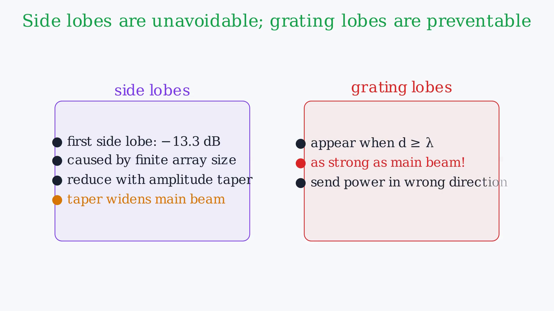
Element count narrows the main beam roughly as 1/N; amplitude taper controls side lobes and spacing controls grating lobes. Side lobes are not the only complication.If the element spacing d exceeds one wavelength, the denominator sin(ψ/2) can hit zero again at a new angle, creating a grating lobe as strong as the main beam.Grating lobes are usually unacceptable because they send power in an unintended direction.The standard rule to avoid them is to keep the spacing below one wavelength:For most practical broadside arrays the spacing is set to λ/2.Narration transcript
Side lobes are not the only complication. If the element spacing d exceeds one wavelength, the denominator sine of psi over two can hit zero again at a new angle, creating a grating lobe as strong as the main beam. Grating lobes are usually unacceptable because they send power in an unintended direction. The standard rule to avoid them is to keep the spacing below one wavelength: d less than lambda. For most practical broadside arrays the spacing is set to lambda over two.
7. Summarize the uniform linear array in three insights
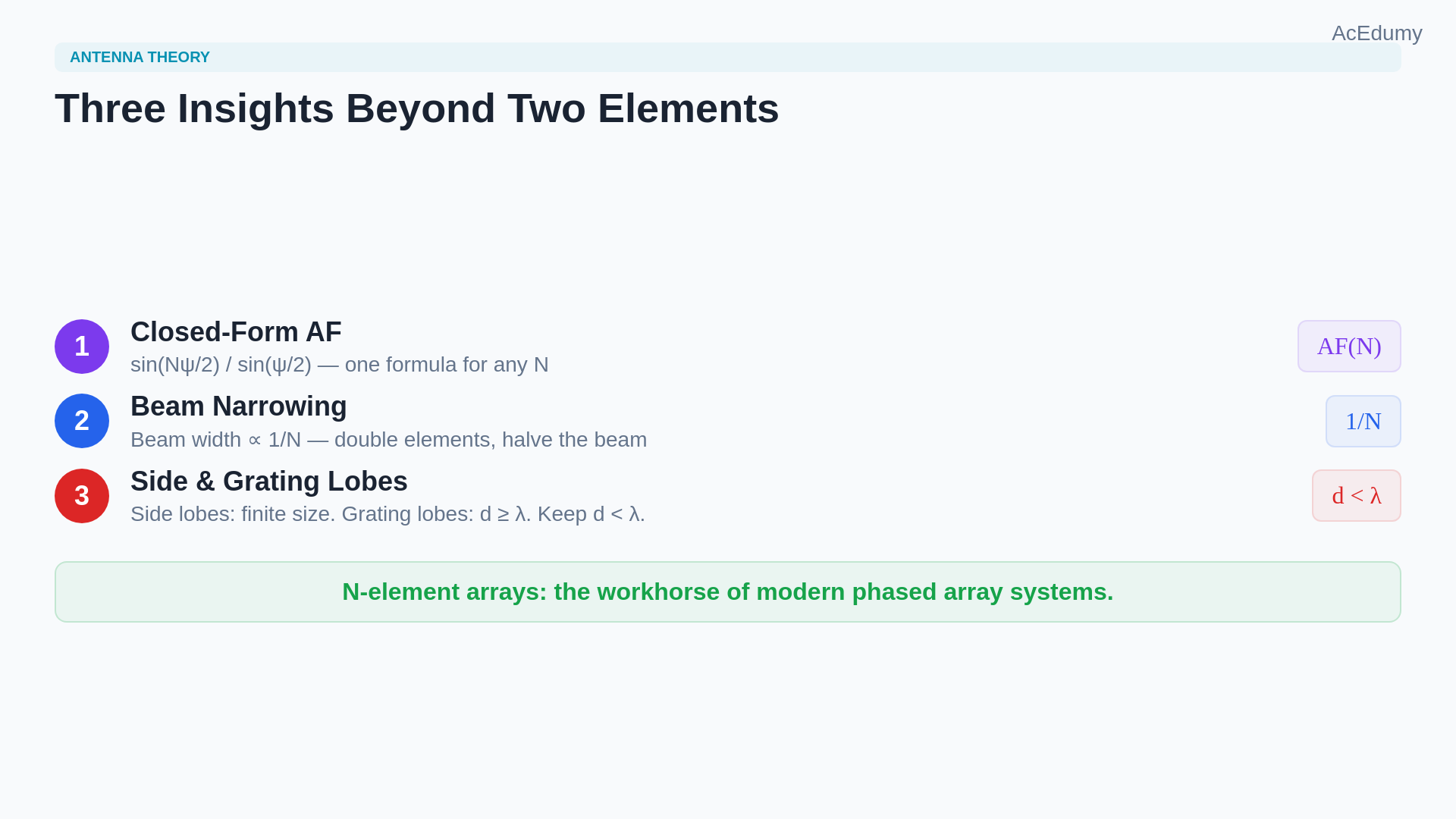
Element count narrows the main beam roughly as 1/N; amplitude taper controls side lobes and spacing controls grating lobes. The N-element uniform linear array adds three insights beyond the two-element case.First, the array factor becomes sin(Nψ/2)/sin(ψ/2).Second, the beam width narrows as 1/N, so more elements produce a sharper beam.Third, side lobes and grating lobes appear and must be managed through amplitude tapering and spacing constraints.Narration transcript
The N-element uniform linear array adds three insights beyond the two-element case. First, the array factor becomes sine of N psi over two divided by sine of psi over two. Second, the beam width narrows as one over N, so more elements produce a sharper beam. Third, side lobes and grating lobes appear and must be managed through amplitude tapering and spacing constraints.
8. Move from array theory to worked problems
Element count narrows the main beam roughly as 1/N; amplitude taper controls side lobes and spacing controls grating lobes. We now have the complete array factor toolkit: from a single element through two-element steering to N-element beam shaping.The next step is to apply these tools to concrete problems — calculating beam widths, plotting array factors for specific configurations, and checking directivity.That is where worked examples come in.Narration transcript
We now have the complete array factor toolkit: from a single element through two-element steering to N-element beam shaping. The next step is to apply these tools to concrete problems — calculating beam widths, plotting array factors for specific configurations, and checking directivity. That is where worked examples come in.
Source video: Antenna Theory #12 | N-Element Linear Array | Beam Width, Side Lobes & Grating Lobes (4:07)