Circuit Theory 1 · Operational Amplifiers
#35 Operational Amplifiers #35 — Integrator and differentiator
Derives the R-C op-amp integrator and differentiator equations and interprets their step, ramp, and sinusoidal responses.
Question
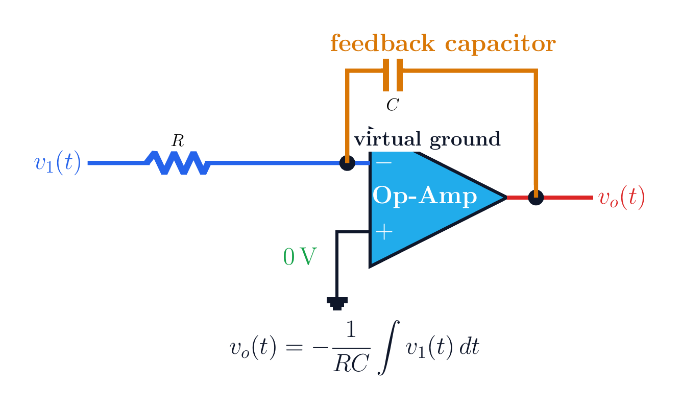
Compare ideal op-amp integrator and differentiator circuits. Derive their transfer and time-domain equations. For the integrator, analyze the ramp response to a step; for the differentiator, analyze ramp and sine inputs. State the zero-initial-condition assumption and practical bandwidth limits.
Written solution and narration transcript(shows the full solution)
Below are all the lines written in the notebook together with the full narration transcript.
1. Integrator circuit
Under negative feedback, the minus input is a conditional virtual ground. Op-amp integratorInput path: V1→R→v−Feedback element: CUnder negative feedback, v−≈0Ideal input current:The input current flows into CNarration transcript
Now let's look at the op-amp integrator circuit. Notice the key difference from circuits we've seen before — the feedback element is a capacitor, not a resistor. The input signal V1 passes through resistor R to the inverting input, while capacitor C provides the feedback path. Since the non-inverting input is grounded, we still have a virtual ground at the inverting node.
2. Integrator derivation
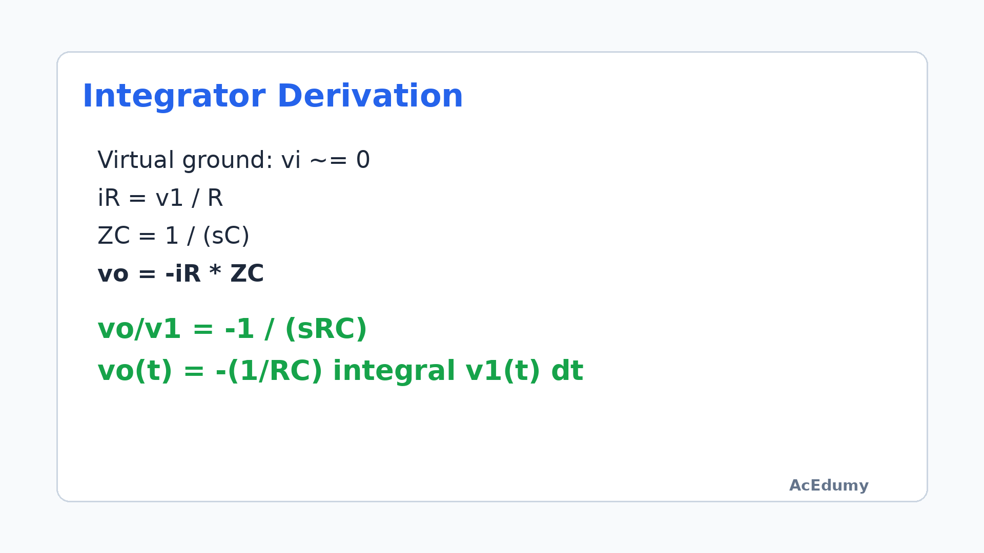
With zero initial condition, the output is the negative scaled integral of the input. Integrator equationZC=1/(sC)Vo(s)/V1(s)=−1/(sRC)vo(t)=−(1/RC)∫v1(t)dtThis form assumes zero initial conditionMinus sign: inverting connectionNarration transcript
Let's derive the transfer function. The capacitive impedance is X C equals 1 over s C in Laplace notation. The current through R is V1 over R. This same current flows through the feedback capacitor, producing an output voltage. Working through the math, we get V out over V1 equals negative 1 over s C R. Converting to the time domain, the output equals negative 1 over R C times the integral of the input. The op-amp integrator literally performs mathematical integration.
3. Step example
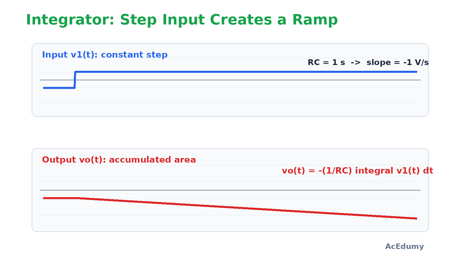
Reducing R C increases the magnitude of the ramp slope. Step input → ramp outputR=1 MΩ, C=1 µF ⇒ RC=1 sdvo/dt=−v1/(RC)=−1 V/sR=100 kΩ ⇒ RC=0.1 sdvo/dt=−10 V/sSmaller RC ⇒ steeper rampNarration transcript
Let's see this in action with a step input. When V1 is a constant 1 volt and R is 1 megohm, C is 1 microfarad, the scale factor 1 over RC equals 1. The output is a negative ramp, growing linearly over time. Now if we change R to 100 kilohms, 1 over RC becomes 10, and the output ramp is ten times steeper. The RC product controls how fast the integrator ramps.
4. Integrator summary
Reducing R C increases the magnitude of the ramp slope. Integrator summaryR at the input, C in feedbackStep → rampSlope: −v1/(RC)Accumulates area over timeA practical integrator adds a resistor across C to limit DC gainPurpose: delay saturationNarration transcript
So the integrator converts a step into a ramp. The output is the negative integral of the input, scaled by 1 over RC. This is fundamental to analog computing and control systems.
5. Differentiator circuit
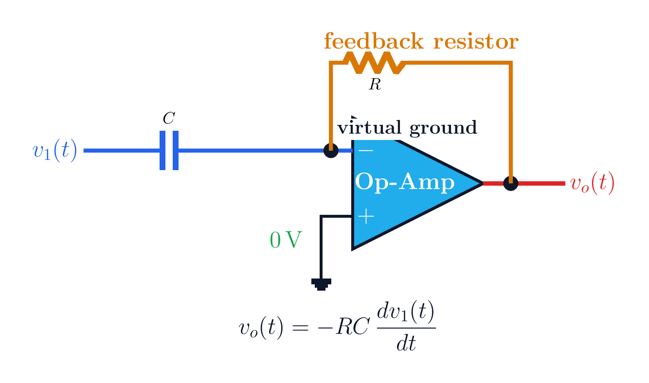
Swapping R and C relative to the integrator produces differentiation. Op-amp differentiatorInput path: V1→C→v−Feedback element: RUnder negative feedback, v−≈0R and C swap relative to the integratorOutput measures the input rate of changeNarration transcript
The differentiator circuit is essentially the mirror image of the integrator. Here, the capacitor is in the input path and the resistor provides feedback. The input signal passes through capacitor C to the inverting node, and resistor R connects from output back to this node.
6. Differentiator derivation
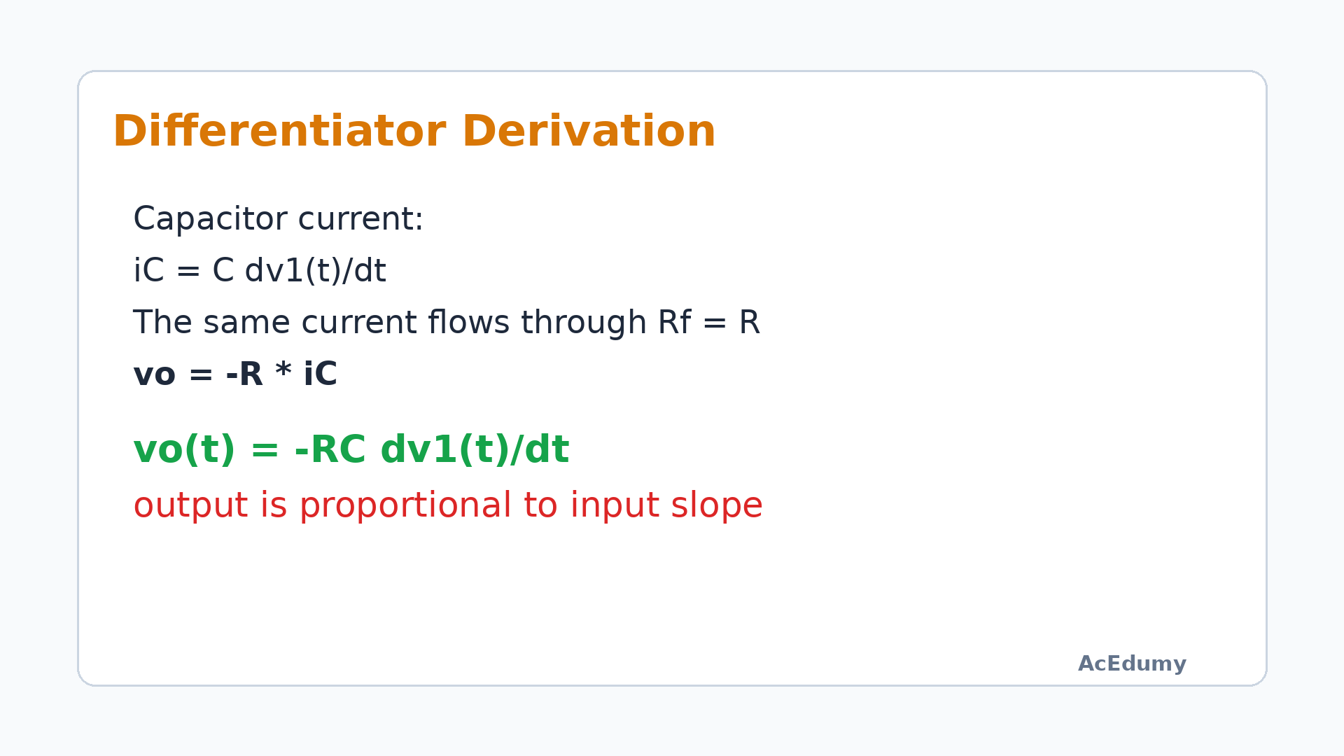
The output is the input rate of change scaled by negative R C. Differentiator equationiC=C·dv1/dtvo=−RiRvo(t)=−RC·dv1(t)/dtScale factor: −RCMinus sign: inverting connectionNarration transcript
For the differentiator, the input current through the capacitor is C times the derivative of the input voltage. This current flows through the feedback resistor R, giving us the output. The result is: v out equals negative RC times the derivative of v1 with respect to time. The scale factor is negative RC.
7. Ramp and sine
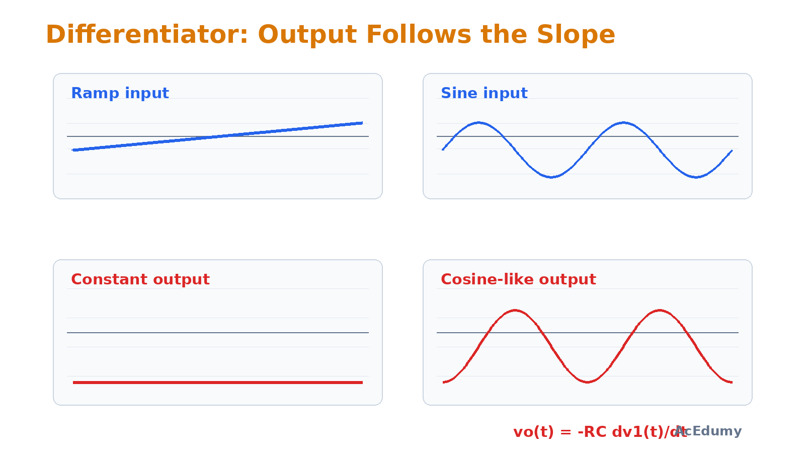
A ramp becomes a constant, while a sine becomes a phase-shifted cosine. Reading differentiator signalsDerivative of a ramp = constantPositive slope ⇒ negative constant outputvo=−ωRCVm cos(ωt)Magnitude grows with frequencyOutput represents rate of changeNarration transcript
When we apply a ramp input to the differentiator, the derivative of a ramp is a constant, so the output is a steady DC voltage scaled by negative RC. For a sinusoidal input, the derivative of sine is cosine, so the output is a cosine waveform. The differentiator produces the rate of change of the input signal.
8. Comparison
Under negative feedback, the minus input is a conditional virtual ground. Integrator ↔ differentiatorIntegrator: R input, C feedbackDifferentiator: C input, R feedbackIntegrator accumulates areaDifferentiator measures slopeBoth are invertingTwo building blocks of analog computingNarration transcript
Comparing the two circuits: the integrator has R in the input and C in the feedback, while the differentiator swaps them. The integrator smooths signals by accumulating area under the curve. The differentiator highlights rapid changes by computing the slope. Together, they form the building blocks of analog computing.
9. Method summary
The output is the input rate of change scaled by negative R C. Method summaryvo,int=−(1/RC)∫vi dtvo,diff=−RC·dvi/dtStep → ramp; ramp → constantIdeal equations require negative feedback and no saturationA practical differentiator limits high-frequency gainFinal check: bandwidth, noise, and railsNarration transcript
To summarize: The integrator output equals negative 1 over RC times the integral of the input — it converts steps to ramps. The differentiator output equals negative RC times the derivative — it converts ramps to steps. These two circuits are fundamental to signal processing and control system design.