Circuit Theory 1 · Operational Amplifiers
#34 Operational Amplifiers #34 — Summing amplifier and unity follower
Explains the unity follower as a buffer, derives the weighted inverting-sum equation, and solves two numerical cases.
Question
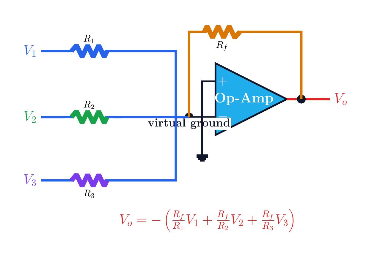
Explain the gain and buffering role of an ideal op-amp unity follower. Derive the three-input inverting summing-amplifier equation by KCL. Solve Example 14.5(a) and (b), then interpret the equal-resistor special case and the condition for linear operation.
Written solution and narration transcript(shows the full solution)
Below are all the lines written in the notebook together with the full narration transcript.
1. Unity follower
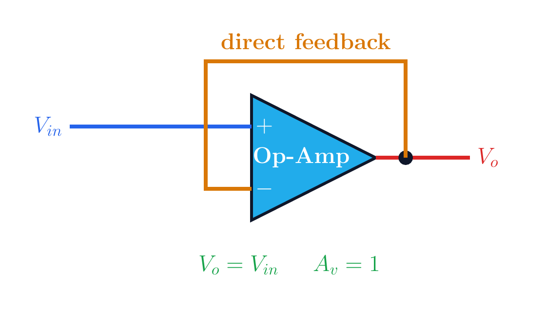
The output is wired directly to the minus input, giving an ideal closed-loop gain of one. Unity voltage followervo wired directly to v−Ideal negative feedback:High Zin, low ZoutPurpose: isolate stages without loadingNarration transcript
Before we dive into the summing amplifier, let's quickly look at a special case of the non-inverting amplifier. The unity follower. In this configuration, the output is connected directly back to the inverting input, with no resistors in the feedback path. This means the voltage gain is exactly one. V out equals V in. It acts as a buffer, providing high input impedance and low output impedance, which is perfect for isolating stages in a circuit.
2. Summing circuit
Each source reaches the summing node through its own resistor, while R_f closes the feedback path. Inverting summing amplifierV1→R1, V2→R2, V3→R3All inputs meet at the minus nodeIdeal input current:Rf returns output to the summing nodeEach input receives its own weightNarration transcript
Now let's look at the summing amplifier, one of the most useful op-amp circuits. Here we have three input voltages, V1, V2, and V3, each connected through its own input resistor, R1, R2, and R3, to the inverting input of the op-amp. The feedback resistor Rf connects from the output back to this same node.
3. KCL derivation
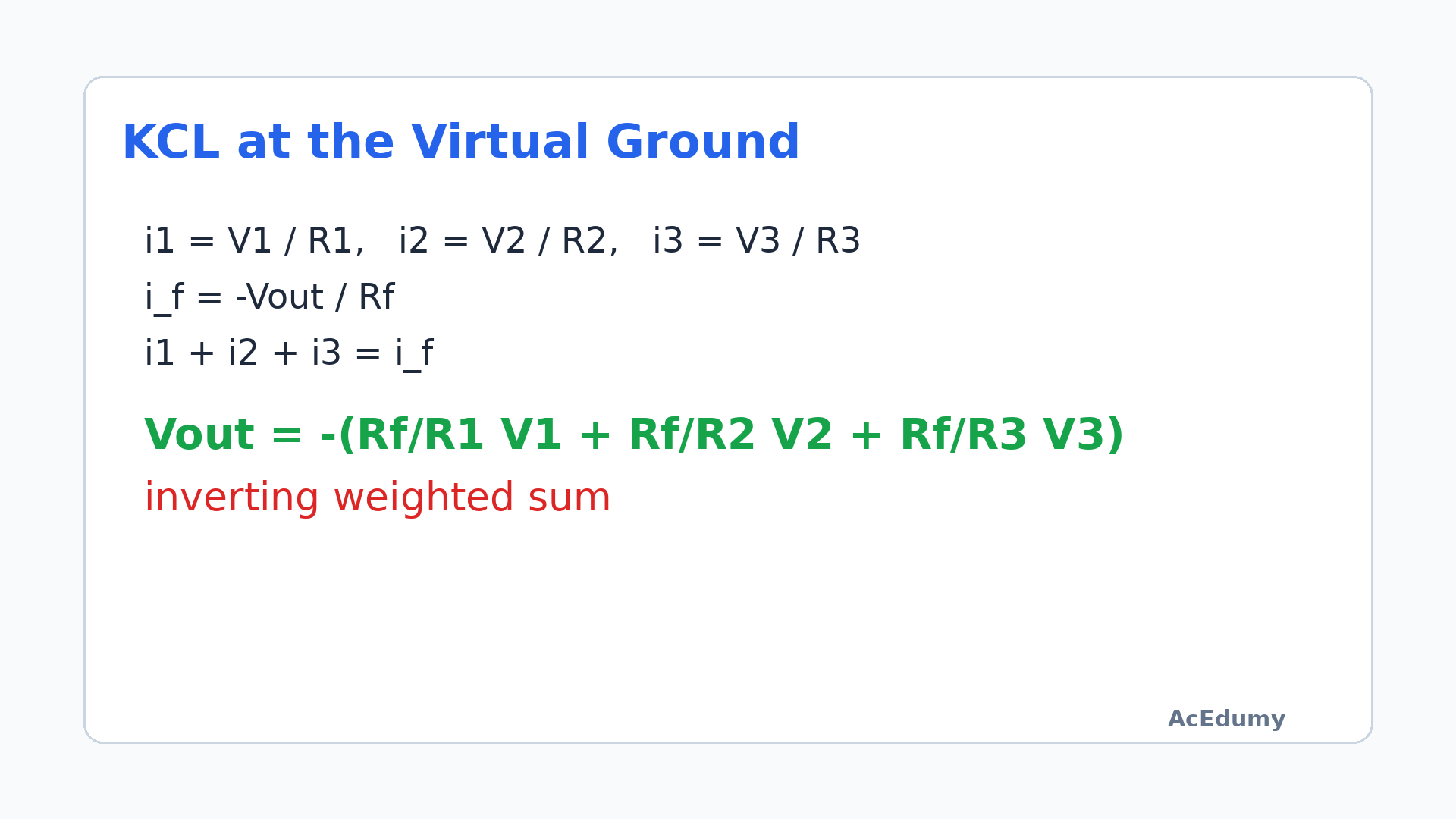
Under the virtual-node condition, the input-current sum equals the feedback current. General equation from KCLWeight of input k: Rf/RkCondition: negative feedback and no saturationNarration transcript
Let's derive the output voltage formula using Kirchhoff's Current Law at the inverting input node. Since this is a virtual ground, the voltage here is approximately zero. The current through each input resistor is simply the input voltage divided by its resistance. By KCL, the sum of input currents equals the feedback current. Rearranging, we get: V out equals negative the sum of Rf over R1 times V1, plus Rf over R2 times V2, plus Rf over R3 times V3. Notice the negative sign, this is an inverting summing amplifier.
4. Example 14.5(a)
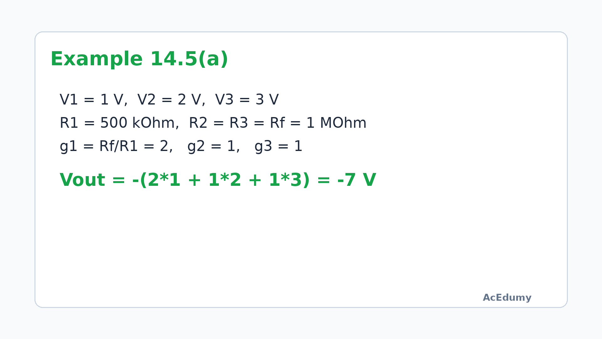
The first input is weighted by two and the other two inputs by one. Example 14.5(a)Narration transcript
Let's solve Example 14.5 part a. We have V1 equals plus 1 volt, V2 equals plus 2 volts, V3 equals plus 3 volts. The resistors are R1 equals 500 kilohms, R2 and R3 each equal 1 megohm, and Rf equals 1 megohm. Substituting into our formula: V out equals negative of 1000k over 500k times 1, plus 1000k over 1000k times 2, plus 1000k over 1000k times 3. That gives us negative of 2 plus 2 plus 3, which equals negative 7 volts.
5. Example 14.5(b)
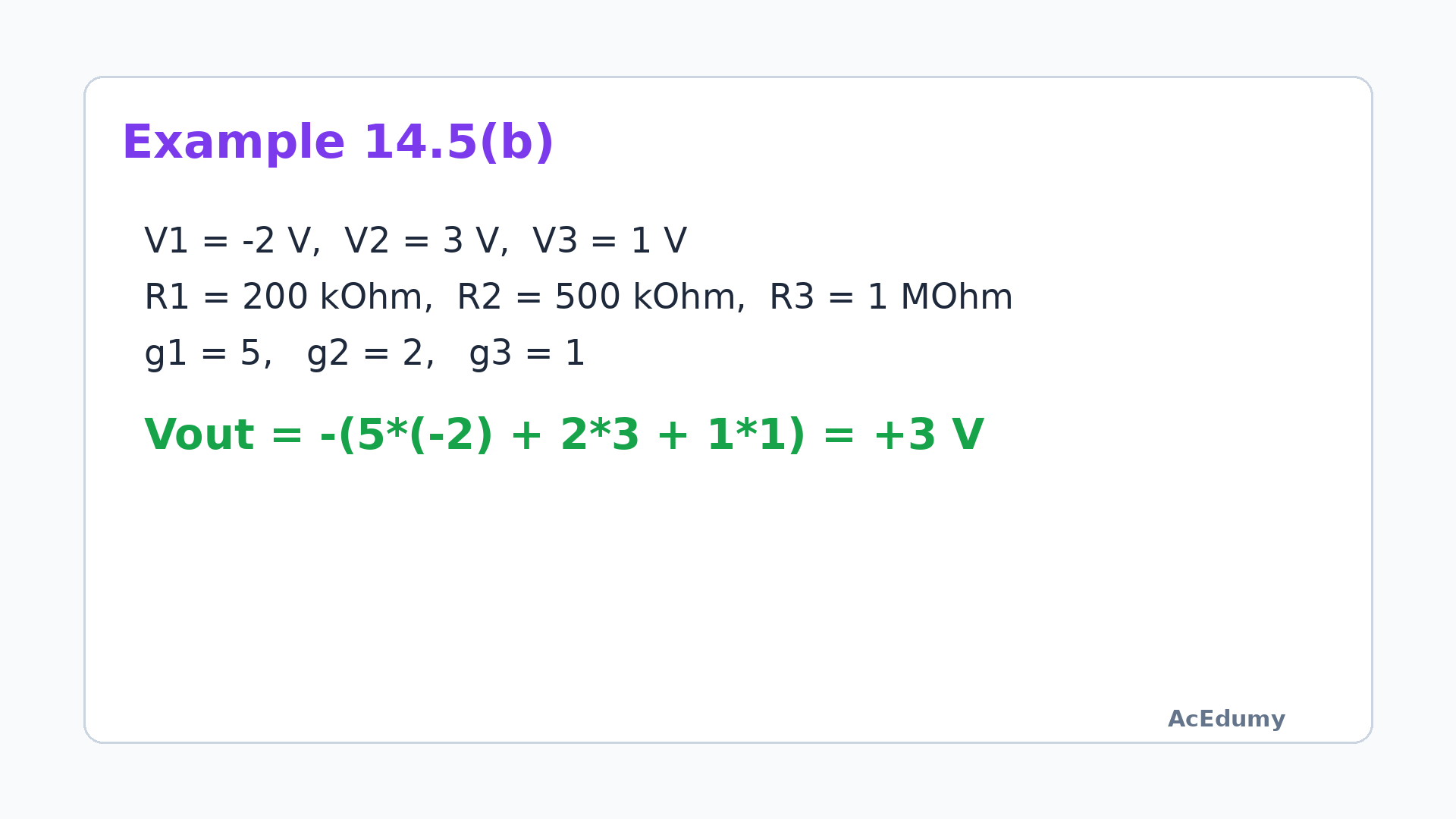
The bracketed sum is minus three, so inversion makes the output plus 3 V. Example 14.5(b)Weights: 5, 2, 1Narration transcript
Now part b, with different values. V1 equals negative 2 volts, V2 equals plus 3 volts, V3 equals plus 1 volt. R1 is 200 kilohms, R2 is 500 kilohms, R3 is 1 megohm, and Rf remains 1 megohm. V out equals negative of 5 times negative 2, plus 2 times 3, plus 1 times 1. That's negative of negative 10 plus 6 plus 1, which equals negative of negative 3, giving us positive 3 volts. Notice how the output can be positive when the weighted sum of inputs is negative.
6. Weighted waveforms
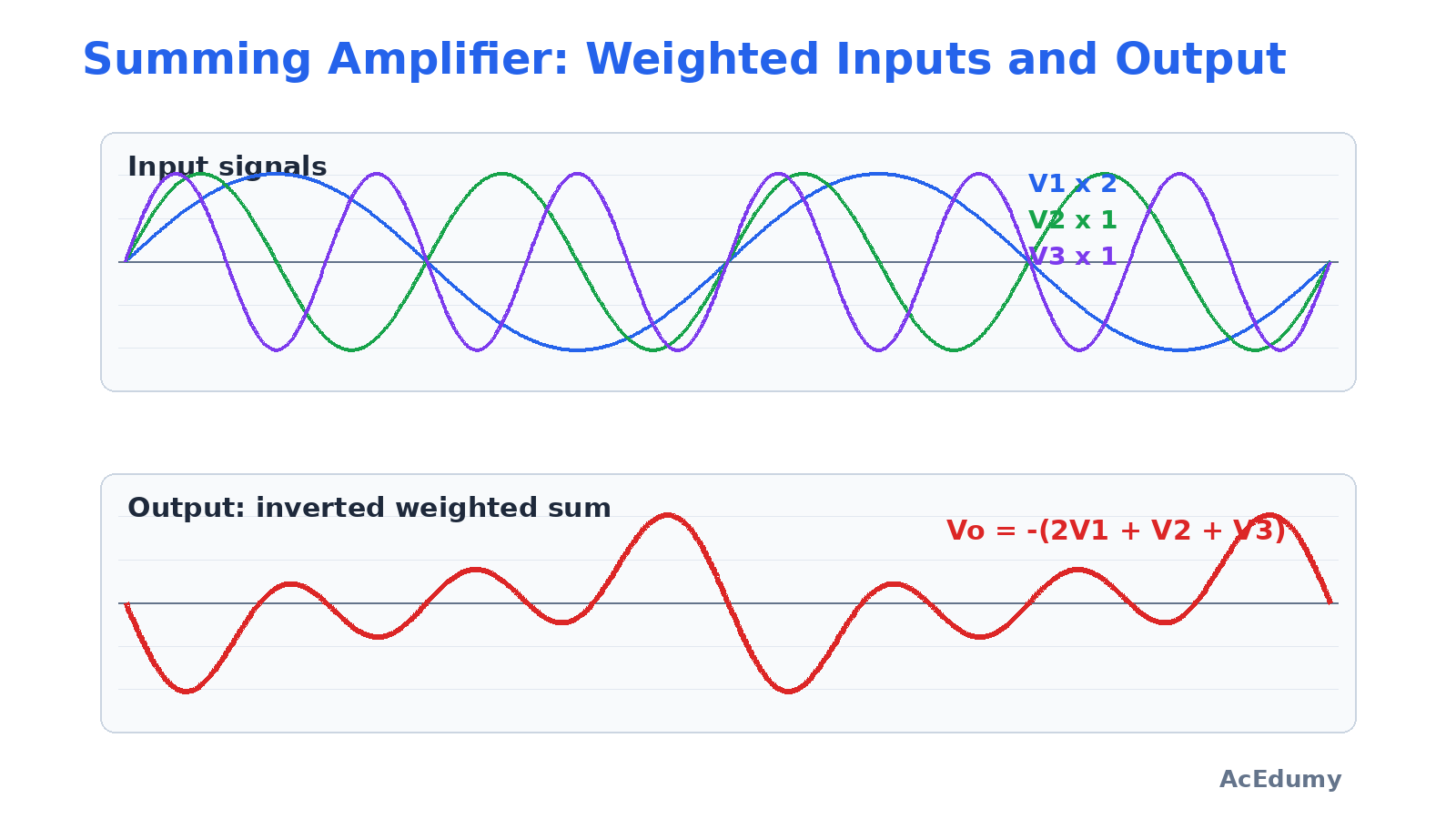
The circuit performs analog weighting and addition in one stage. Analog weighting and additionV1 weight: Rf/R1V2 weight: Rf/R2V3 weight: Rf/R3Weight first, then addInvert the sign at the outputOp amp = simple analog calculatorNarration transcript
Here's a visual comparison of the input and output waveforms. The three input signals are each weighted by their respective gain factors and then summed with an inverted sign at the output. This is essentially what an analog computer does, it performs mathematical addition using op-amp circuits.
7. Equal resistors
Each source reaches the summing node through its own resistor, while R_f closes the feedback path. Equal-resistor special caseUnity-magnitude gain for each inputAudio mixing and signal processingPure inverting adderNarration transcript
An important special case: when all input resistors equal the feedback resistor, R1 equals R2 equals R3 equals Rf, the output simplifies to V out equals negative the sum of V1 plus V2 plus V3. This is a pure inverting adder with unity gain on each input. This configuration is widely used in audio mixing and signal processing.
8. Method summary
Under the virtual-node condition, the input-current sum equals the feedback current. Method summaryFollower: Av=1 and bufferingSummer: weight each input by Rf/RkEqual resistors:The virtual-node rule is conditionalFinal check: supply rails and saturationNarration transcript
To summarize: The summing amplifier adds multiple weighted inputs with sign inversion. The key formula is V out equals negative of Rf over R1 times V1 plus Rf over R2 times V2 plus Rf over R3 times V3. Each input has its own gain factor determined by the ratio of Rf to its input resistor. And when all resistors are equal, you get a simple inverting adder.