Circuit Theory 1 · Operational Amplifiers
#31 Operational Amplifiers #31 — Op-Amp basics
Introduces the op-amp symbol, ideal-model assumptions, supply limits, and the first inverting circuit.
Question
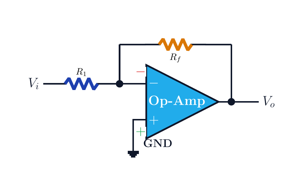
Explain the essential terminals and ideal-model assumptions of an operational amplifier; show how the input signs affect the output and identify the negative-feedback path in a basic inverting circuit.
Written solution and narration transcript(shows the full solution)
Below are all the lines written in the notebook together with the full narration transcript.
1. What is an op amp?
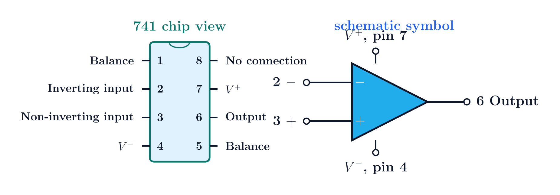
The essential analysis pins are 2, 3, 6, 7, and 4. What is an op amp?Operational amplifierMany internal parts, one external blockComparison and voltage followingInverting / non-inverting gainSumming, differentiation, integrationAn amplifier that performs signal operationsNarration transcript
In this lesson, the goal is not to solve a long numerical problem yet. The goal is to meet the operational amplifier, or op amp, and understand what kind of circuit element it represents. An op amp is built from many transistors, resistors, capacitors, and diodes, but in circuit theory we usually treat it as one block. That block can be used for comparison, voltage following, inverting amplification, non-inverting amplification, summing, differentiation, integration, and many other operations. So the name operational amplifier is literal: it is an amplifier used to perform operations on signals.
2. Symbol and pins
The essential analysis pins are 2, 3, 6, 7, and 4. Symbol and essential pins741: a common op-amp examplePin 2: inverting input (−)Pin 3: non-inverting input (+)Pin 6: output voPin 7: +VCC; pin 4: −VCCSupply pins are required even if omittedNarration transcript
Now let us connect the physical part to the schematic symbol. A common op amp such as the seven forty one has several package pins. For circuit analysis, the most important pins are the inverting input, the non-inverting input, the output, and the two supply pins. The inverting input is marked with a minus sign. The non-inverting input is marked with a plus sign. The output is drawn at the tip of the triangle. The supply pins, V plus and V minus, power the device, even when they are not always drawn in every small signal schematic.
3. Ideal model
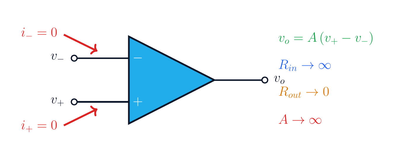
In the ideal model A and R_in approach infinity while R_out approaches zero. Ideal op-amp modelA→∞Rin→∞Rout→0These are ideal analysis assumptionsNarration transcript
For the first pass, we use the ideal op amp model. There are three assumptions to keep in mind. First, the open loop gain is extremely large, so ideally A goes to infinity. Second, the input resistance is extremely large, so no current enters either input terminal. We write i plus equals zero and i minus equals zero. Third, the output resistance is approximately zero, so the op amp behaves like a strong voltage source at its output. The basic controlled-source idea is v output equals A times v plus minus v minus.
4. Output limits
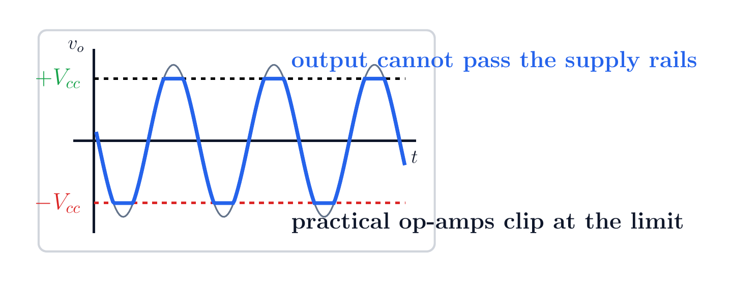
A practical output cannot move beyond its supply limits. Output limitsAn op amp does not create energyDemand beyond a rail causes saturationThe waveform clipsReal swing may not reach the railsCheck the device data sheetNarration transcript
The ideal model is a tool, not a real power supply. In a practical op amp, the output voltage cannot become larger than the supply rails. If the op amp is powered from plus V C C and minus V C C, then the output is limited to that range. When the requested output tries to go beyond the rail, the waveform clips. So when we analyze op amp circuits, we first use the ideal rules, but we also remember that the final output must stay inside the available supply range.
5. Input signs
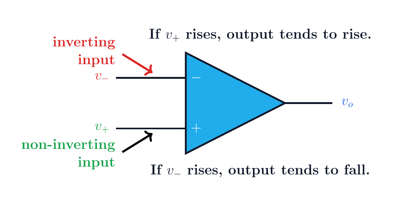
Raising v_+ raises the output; raising v_- lowers it. Input signsv+↑ → vo↑v−↑ → vo↓vo=AvdOpen-loop operation is very sensitiveThe signs set the feedback directionNarration transcript
The plus and minus signs tell us the direction of the effect. If the non-inverting input, v plus, becomes larger, the output tends to rise. If the inverting input, v minus, becomes larger, the output tends to fall. That is why the upper input is called inverting: a positive change there pushes the output in the opposite direction. This sign convention is the key to understanding why feedback can force the two input voltages to become almost equal in many linear op amp circuits.
6. First inverting circuit
R_f feeds the output back to the minus-input node. First circuit — inverting formVi → R1 → minus inputPlus input → groundOutput: VoRf: Vo back to the minus inputThis path is negative feedbackGoal: controlled linear gainNarration transcript
Here is the first circuit we will recognize: the basic inverting op amp. Read it slowly from left to right. The input voltage V i passes through resistor R one and reaches the minus input node. The plus input is connected to ground. The output is V o on the right. A feedback resistor R f connects the output back to the same minus input node. This feedback path is not decoration. It is the path that makes the circuit operate as a controlled amplifier instead of as an open loop comparator.
7. Feedback path
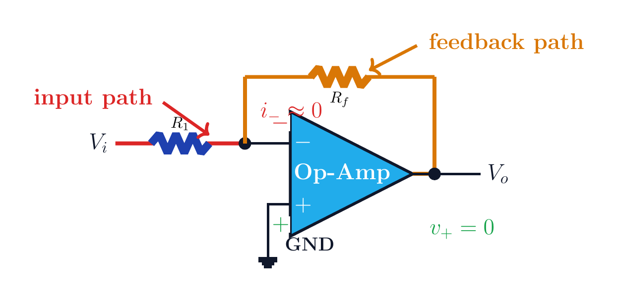
Virtual ground applies only with negative feedback in linear, unsaturated operation. Input and feedback pathsInput: Vi → R1 → v−Feedback: Vo → Rf → v−Negative feedback + linear region:v−≈0 V: conditional virtual groundNarration transcript
Let us mark the important parts. The red path is the input path through R one into the minus input node. The orange path is the feedback path through R f from the output back to that same node. Because the ideal op amp input current is zero, almost no current enters the minus terminal. Since the plus terminal is grounded, v plus is zero. In the next lesson, negative feedback will let us treat the minus node as almost zero volts as well. That idea is called virtual ground, and it leads to the inverting amplifier gain formula.
8. Method summary
R_f feeds the output back to the minus-input node. Method summaryPlus input, minus input, and outputA→∞, Rin→∞, Rout→0Output is limited by the supply railsRf supplies feedback in the inverting formNext: inverting-amplifier gainNarration transcript
So the handoff from this introduction is simple. An op amp has a plus input, a minus input, an output, and supply limits. In the ideal model, the input currents are zero, the input resistance is infinite, the output resistance is zero, and the gain is very large. The first circuit to recognize is the inverting op amp: V i goes through R one to the minus input, the plus input is grounded, and R f feeds the output back to the minus input. Next, we will calculate exactly how that circuit amplifies and inverts the input signal.
Source video: Circuit Theory #31 | Operational Amplifiers - Op-Amp Basics (5:13)