Electronics 1 · Electronics Basics
#08 Parallel biased clippers — variations 9–12
Distinguish all four parallel biased clippers with min/max rules and find both ideal and 0.7 V silicon thresholds.
Question
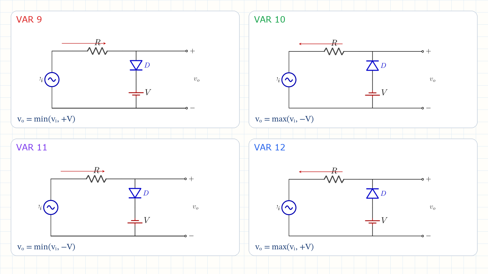
For v_i = 10 sin(ωt) V and V = 3 V, analyze the four parallel biased clippers shown. For each circuit, determine the input region in which the diode is ON or OFF, the ideal output rule v_o(t), whether it is an upper or lower limiter, and the transition voltage. Then correct all four transitions for a silicon diode with V_D = 0.7 V.
Written solution and narration transcript(shows the full solution)
Below are all the lines written in the notebook together with the full narration transcript.
1. What bias changes
Battery direction sets the signed reference; diode direction selects upper or lower limiting. Parallel simple clipper: D ON → vo = 0Add a DC source in series with DD ON → vo = +V or −VD OFF → iD = 0 → vo = vi2 diode directions × 2 battery directions = 4 circuitsNarration transcript
Welcome back. In the last lesson we built two parallel simple clippers. The diode sat in parallel with the output, and when it turned on it pulled the output to zero. But the clipping level was always exactly zero volts. Today we keep the same parallel topology, but we add a DC battery in series with the diode, inside the shunt branch. This battery moves the clipping level away from zero. When the diode turns on now, the output does not go to zero. It locks at the battery voltage, plus V or minus V. The parallel biased clipper acts like a voltage limiter. It lets the signal pass until it reaches a threshold, and then it clamps the output at that threshold. We have two choices again. The diode orientation: positive or negative. And the battery direction: one or two. Two times two gives four parallel biased clippers.
2. Transition method
Battery direction sets the signed reference; diode direction selects upper or lower limiting. At transition: iD = 0 and vD = 0Battery direction 1 → reference +VBattery direction 2 → reference −VDiode direction selects the conducting sideNarration transcript
The method is the same as before. At the switching instant, the current i is zero and the diode voltage v D is zero. Apply Kirchhoff's voltage law around the shunt branch. With i equal to zero, there is no voltage drop across the series resistor R, so v o equals v i at the transition point. In the shunt branch, with v D equal to zero, v o equals plus V or minus V depending on the battery direction. That gives the transition voltage. Direction one places the transition at plus V. Direction two places it at minus V. Once you know the transition voltage, the rule is simple. On one side of the transition, the diode is on, and v o is locked at the battery voltage. On the other side, the diode is off, no current flows through the shunt branch, and v o equals v i.
3. Variation 9
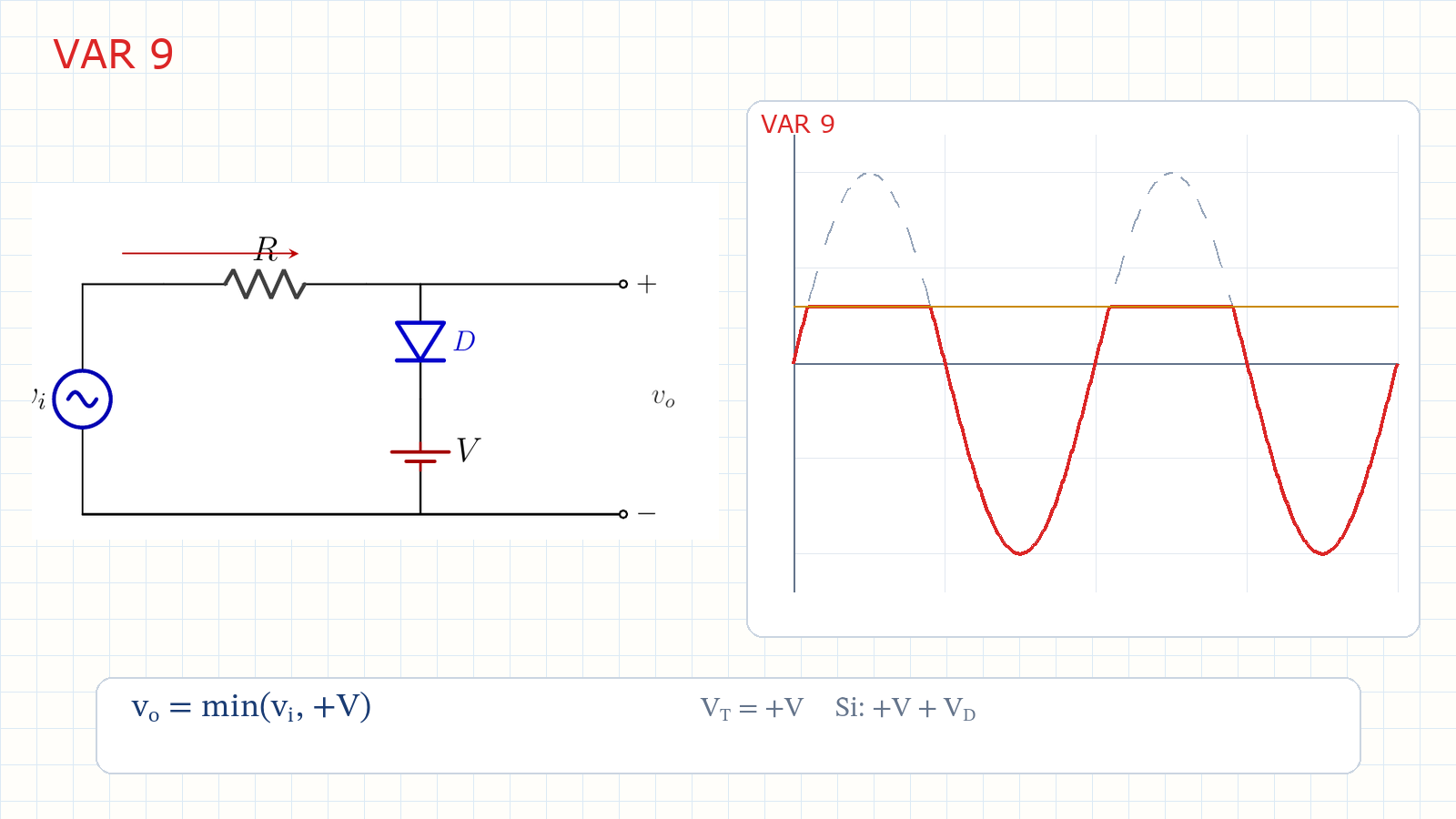
v_o = min(v_i,+V); the silicon transition is +V+V_D. VAR 9: positive D, battery direction 1vi > +V → D ON → vo = +Vvi ≤ +V → D OFF → vo = vivo = min(vi,+V)The battery sets the +3 V ceilingNarration transcript
Variation nine: positive, parallel, biased, direction one. The diode is in the same orientation as the positive parallel simple clipper. The battery sits in series with it in the shunt branch, direction one. The transition voltage is plus V, plus three volts. When v i is above plus three volts, the diode turns on. The shunt branch conducts and the output locks at plus three volts. The positive peak of the sine, which would normally reach plus ten, is clipped flat at plus three. When v i is below plus three volts, the diode is off. No current in the shunt branch, so v o equals v i. The output follows the input for the entire lower region. The result looks like the full sine wave, but with the positive peak sliced off at plus three volts. The battery set the ceiling.
4. Variation 10
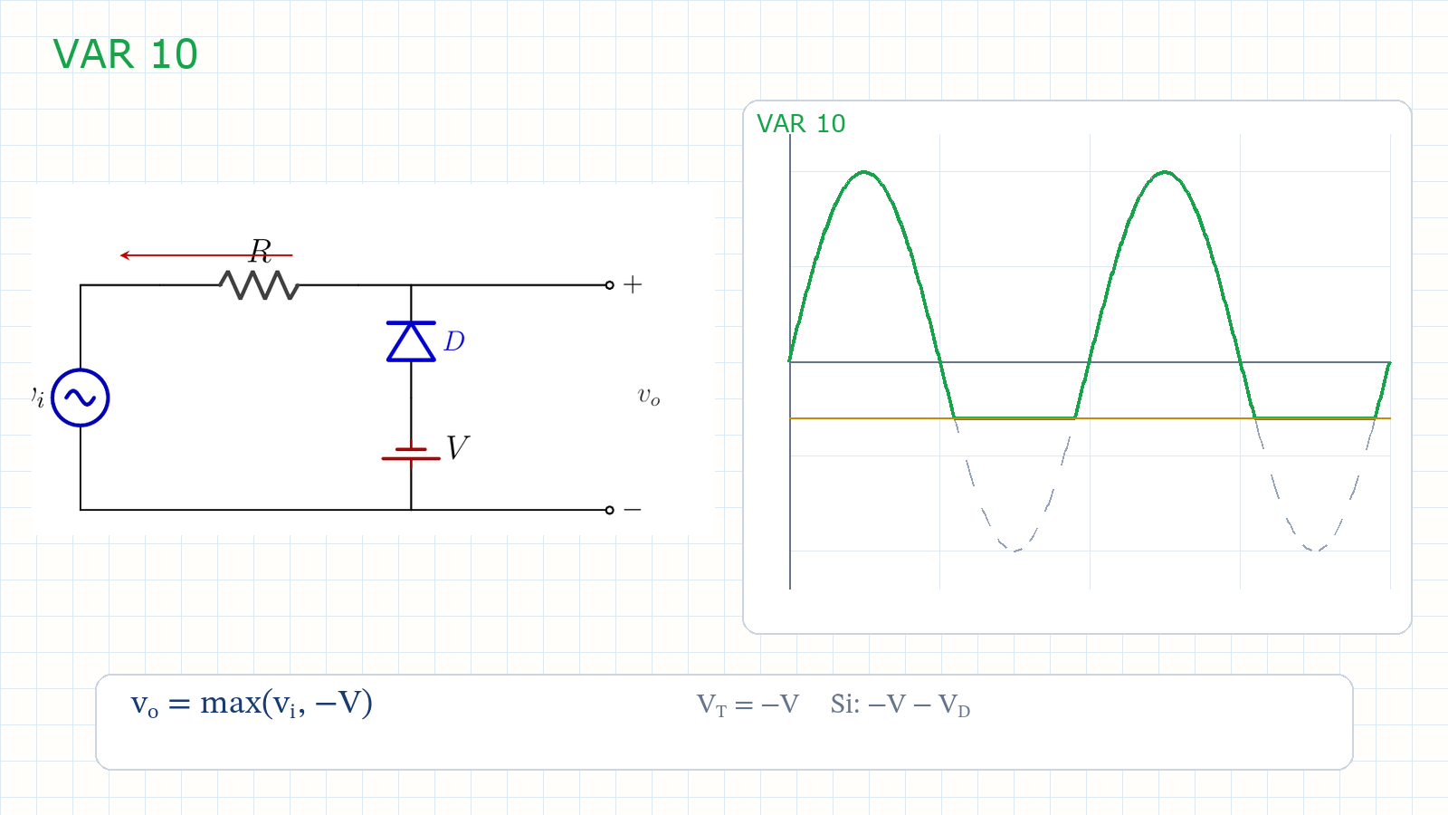
v_o = max(v_i,−V); the silicon transition is −V−V_D. VAR 10: negative D, battery direction 2vi < −V → D ON → vo = −Vvi ≥ −V → D OFF → vo = vivo = max(vi,−V)VAR 10 mirrors VAR 9 about zeroNarration transcript
Variation ten: negative, parallel, biased, direction two. Now the diode is in the negative orientation, and the battery is in direction two. The transition voltage moves to minus V, minus three volts. When v i drops below minus three volts, the diode turns on and the output locks at minus three volts. The negative peak, which would reach minus ten, is clipped flat at minus three. When v i is above minus three, the diode is off, and v o equals v i. The output is the full sine wave with the negative peak sliced off at minus three volts. Variation ten is the mirror of variation nine. One clips the top, the other clips the bottom.
5. Variation 11
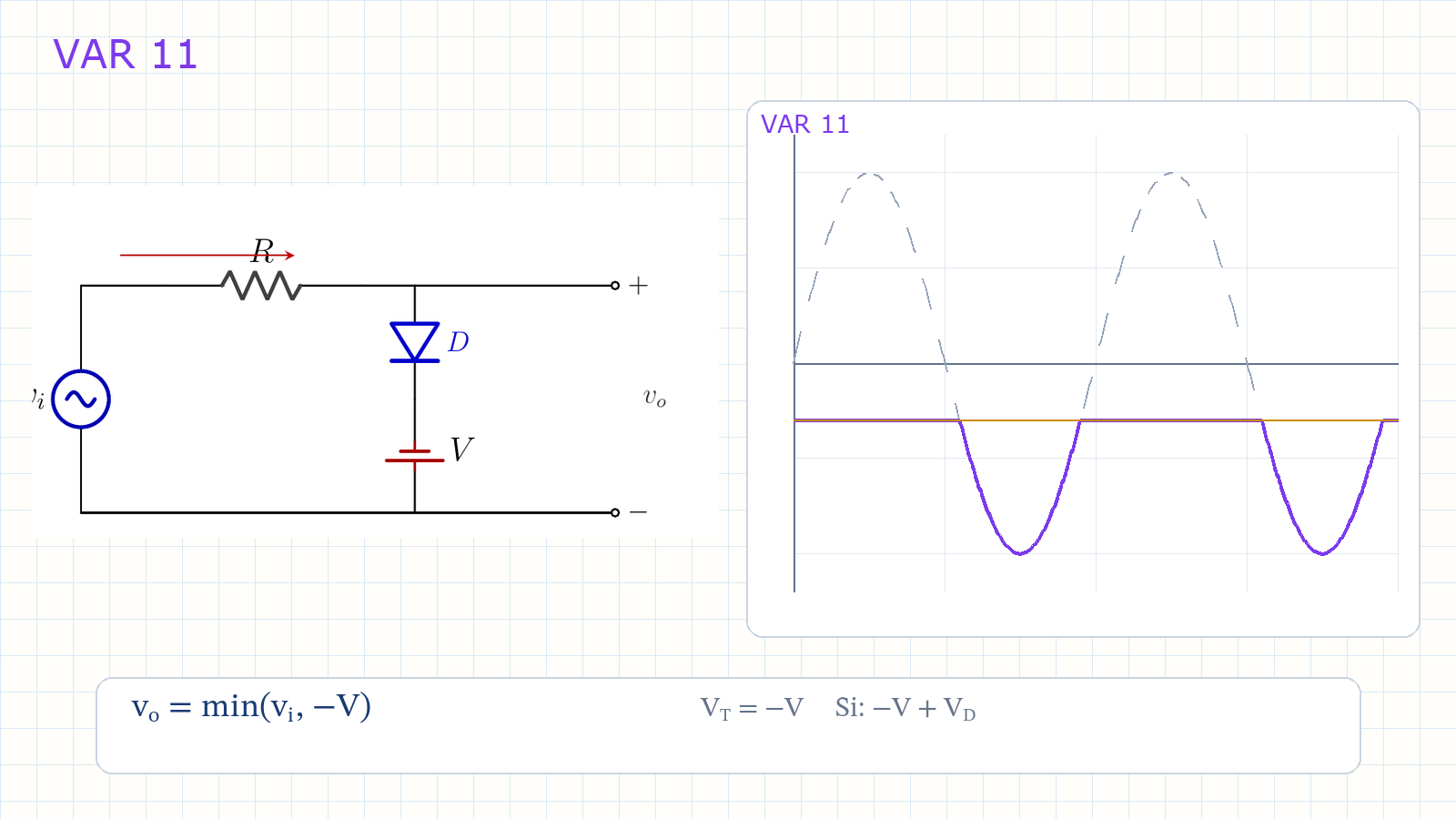
v_o = min(v_i,−V); the silicon transition is −V+V_D. VAR 11: positive D, battery direction 2vi > −V → D ON → vo = −Vvi ≤ −V → D OFF → vo = vivo = min(vi,−V)Ideal: −3 V | Si: −V+VD = −2.3 VNarration transcript
Variation eleven: positive, parallel, biased, direction two. Same positive diode orientation as variation nine, but the battery is now in direction two. Direction two moves the transition to minus V, minus three volts. The diode orientation decides which side of that transition conducts. When v i is above minus three, the diode turns on and locks the output at minus three volts. When v i is below minus three, the diode is off and v o equals v i. So this is an upper limiter placed at a negative level. Most of the cycle is held flat at minus three volts, while only the portion of the negative trough below minus three passes. With a silicon diode, the transition is minus V plus V D, which is minus two point three volts for V equal to three volts.
6. Variation 12
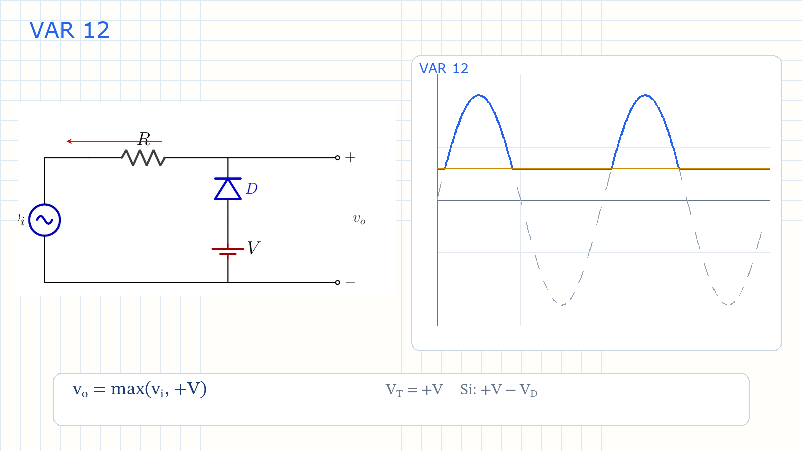
v_o = max(v_i,+V); the silicon transition is +V−V_D. VAR 12: negative D, battery direction 1vi < +V → D ON → vo = +Vvi ≥ +V → D OFF → vo = vivo = max(vi,+V)Ideal: +3 V | Si: +V−VD = +2.3 VNarration transcript
Variation twelve: negative, parallel, biased, direction one. Negative diode orientation, battery direction one. The transition voltage is plus V, plus three volts. This time the reversed diode conducts below the transition. When v i is below plus three, the diode turns on and locks the output at plus three volts. When v i rises above plus three, the diode is off and v o equals v i. So this is a lower limiter placed at a positive level. Most of the cycle is held flat at plus three volts, while only the part of the positive crest above plus three passes. With a silicon diode, the transition is plus V minus V D, or plus two point three volts for a three volt battery.
7. Four-circuit summary
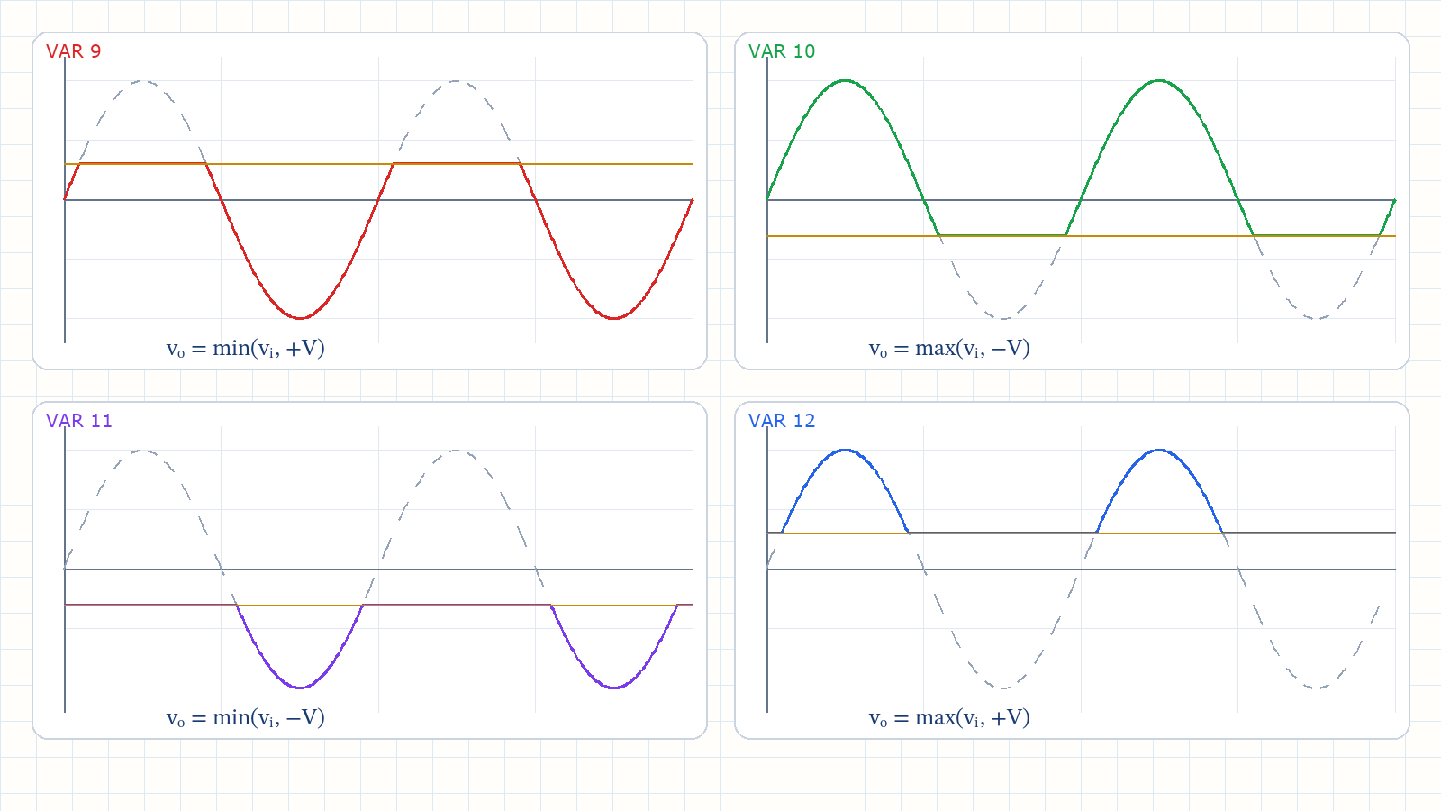
The four orientations produce four distinct min or max rules. Battery sets the reference; D selects upper/lower limitingVAR 9 → upper +V | min(vi,+V)VAR 10 → lower −V | max(vi,−V)VAR 11 → upper −V | min(vi,−V)VAR 12 → lower +V | max(vi,+V)Parallel: D ON → locked at V; D OFF → follows viSi thresholds: +3.7, −3.7, −2.3, +2.3 VNarration transcript
Let us put all four together. Every parallel biased clipper has one resistor in series, and one diode plus one DC battery in the shunt branch. The battery sets the reference level. Direction one places it at plus V, and direction two places it at minus V. The diode orientation decides whether the circuit limits values above or below that reference. When the diode is on, the output is locked at that level, like a voltage limiter. When the diode is off, the output follows the input. Variation nine is an upper limiter at plus V. Variation ten is a lower limiter at minus V. Variation eleven is an upper limiter at minus V. Variation twelve is a lower limiter at plus V. Compare this with the series biased clipper from lesson six. In the series version, the output shifted by V when the diode was on, and dropped to zero when off. In the parallel version, the output locks at V when on, and follows the input when off. One practical note. A real silicon diode shifts the clipping level by about zero point seven volts. For a three volt battery, the four silicon thresholds are plus three point seven, minus three point seven, minus two point three, and plus two point three volts. Next lesson we look at the double source clipper, which uses two diode branches to slice the waveform at two levels simultaneously. See you there.