Electronics 1 · Electronics Basics
#07 Parallel simple clippers — positive and negative shunt diode
Analyze the two ideal parallel simple clippers, explain why shunt conduction clips the output, and include the 0.7 V silicon shift.
Question
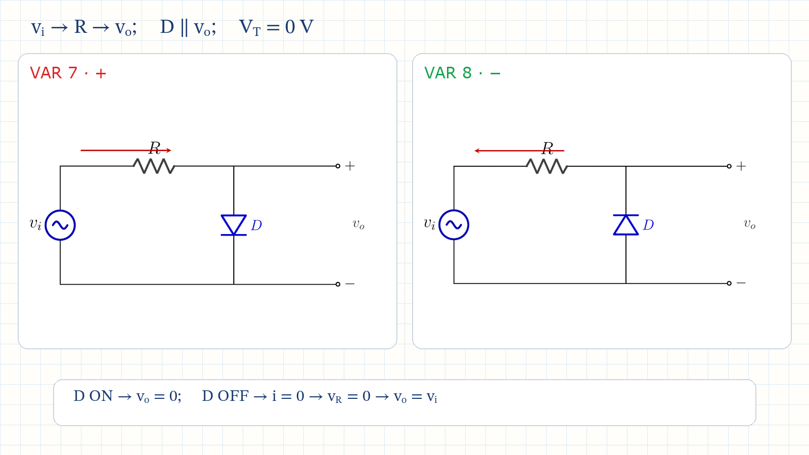
For the two ideal parallel simple clipper circuits, let v_i = V_m sin(ωt). Determine the diode ON/OFF state, v_o(t), and resistor current during each half-cycle. Compare the clipping mechanism with the corresponding series simple clippers, then explain how a 0.7 V silicon model moves the ideal zero-volt clipping levels.
Written solution and narration transcript(shows the full solution)
Below are all the lines written in the notebook together with the full narration transcript.
1. From series to parallel
In a parallel clipper, D ON clamps the output while D OFF lets the input pass without a resistor drop. Series clipper: D lies in the load-current pathParallel clipper: R is series; D shunts the outputD ON → output shorted → vo = 0D OFF → i = 0 → vR = 0 → vo = viSeries and parallel reverse the clipping mechanismNarration transcript
Welcome back. In the last two lessons we built all six series clippers. The diode sat in series with the load resistor, right in the path of the current. When the diode turned on, current flowed through the resistor and the output followed the input. When it turned off, the path was open, the current was zero, and the output dropped to zero. Today we move the diode out of the series path and place it in parallel with the output. This is the parallel clipper. The circuit has a resistor R in series between the input source and the output node. The diode D sits between that output node and ground. The output voltage v o is measured across the diode, not across R like before. When the diode turns on, it acts like a short circuit across the output. That pulls v o down to zero. When it turns off, no current flows through the diode, and if the output is open circuited, no current flows through R either, so v o equals v i. The clipping mechanism is reversed compared to the series clipper. In a series clipper, the diode being off caused zero output. In a parallel clipper, the diode being on causes zero output. But as we will see, the same diode orientation still clips the same half of the waveform.
2. Positive parallel clipper
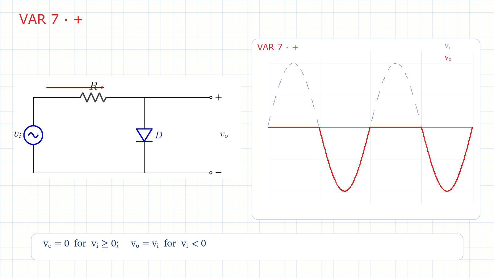
Variation 7 clips the positive half because the shunt diode conducts for positive input. Variation 7: positive parallel simple clippervi > 0 → D ON → vo = 0ON current:vi < 0 → D OFF → iR = 0No drop across R → vo = viPositive half clipped; negative half passesNarration transcript
Variation seven: the positive parallel simple clipper. The diode is connected with its anode at the output node and its cathode at ground. When the input v i is positive, the anode sees a positive voltage through R, while the cathode sits at zero. The diode is forward biased, so it turns on. As a short circuit, it forces v o to zero volts. The current from v i flows through R and through the diode to ground. The resistor R limits this current. So during the entire positive half cycle, the output is clamped at zero. Now when v i goes negative, the anode sees a negative voltage. The cathode is at zero, which is higher than the anode. The diode is reverse biased. It turns off. With the diode off, no current flows through that branch. And with no load on the output, no current flows through R either. So there is no voltage drop across R, and v o equals v i. The negative half cycle passes through to the output. In short: positive half clipped to zero, negative half passes.
3. Positive output waveform
Variation 7 clips the positive half because the shunt diode conducts for positive input. Dashed: vi; solid: vovo = 0 for vi ≥ 0vo = vi for vi < 0Transition voltage:Same waveform as positive series; opposite diode stateNarration transcript
The waveform confirms this. The dashed line is the input, a sine wave with amplitude V m. For the positive portions, the diode is on and the output is held at zero. For the negative portions, the diode is off and the output follows the input. Written as a rule: when v i is greater than zero, v o equals zero. When v i is less than zero, v o equals v i. The transition between on and off happens at v i equals zero. Compare this with the positive series simple clipper from lesson five. That circuit also clips the positive half and passes the negative half. The output waveform looks the same, but the internal mechanism is different. In the series version the diode was off during clipping. In this parallel version the diode is on during clipping.
4. Negative parallel clipper
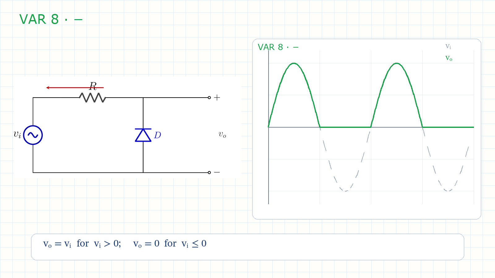
Variation 8 clips the negative half after the diode orientation is reversed. Variation 8: reverse Dvi > 0 → D OFF → vo = vivi < 0 → D ON → vo = 0Positive half passes; negative half is clippedvo = vi for vi > 0; vo = 0 for vi ≤ 0Narration transcript
Variation eight: the negative parallel simple clipper. Reverse the diode. Now the cathode is at the output node and the anode is at ground. When v i is positive, the cathode sees a positive voltage and the anode is at zero. The diode is reverse biased, so it turns off. No current through the diode, no current through R. v o equals v i. The positive half cycle passes through. When v i goes negative, the cathode sees a negative voltage, lower than the anode at zero. The diode is forward biased and turns on. It shorts the output to zero, so v o equals zero during the entire negative half cycle. The result: positive half passes, negative half clipped to zero. That is the naming rule. A negative clipper clips the negative half cycle.
5. Compare both mechanisms
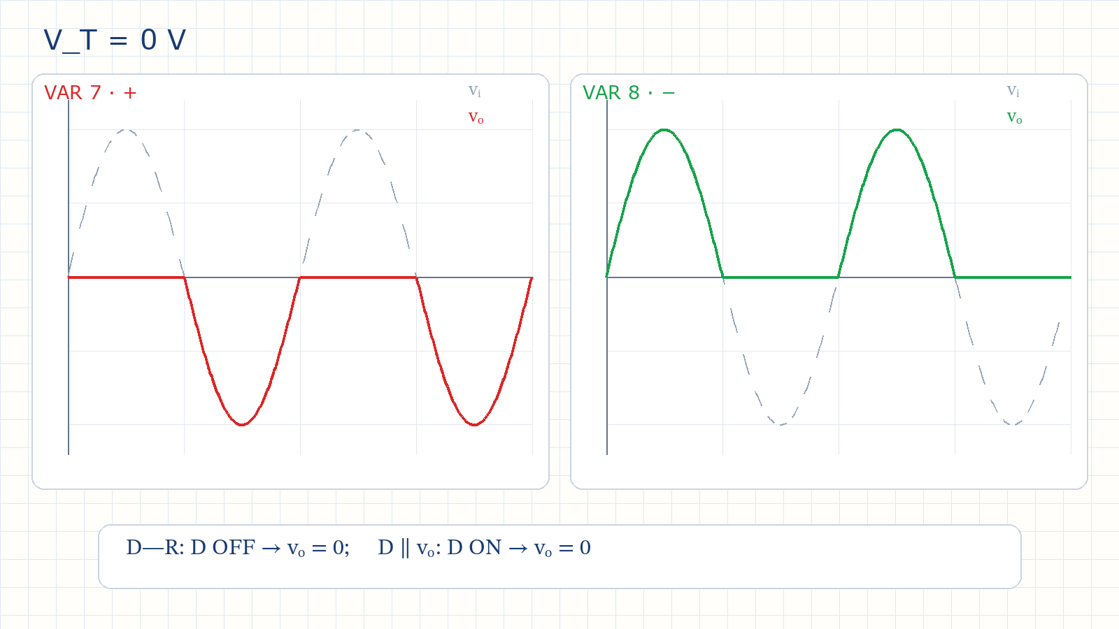
The diode direction selects which half-cycle is clamped to zero. Positive parallel: + half zero; − half passesNegative parallel: − half zero; + half passesIdeal simple clipping level:Series: D OFF causes clippingParallel: D ON causes clippingSame output waveform; different current pathNarration transcript
Put the two circuits side by side. Variation seven clips the positive half and passes the negative half. Variation eight clips the negative half and passes the positive half. The only difference is the diode orientation. Everything else is the same: one resistor in series, one diode in parallel with the output, and no DC bias source. These are simple parallel clippers because the clipping level is zero volts. Now compare parallel with series. A positive series clipper and a positive parallel clipper produce the same output waveform, both clipping the positive half to zero. But look at the diode during the clipping region. In the series clipper, the diode is off. It blocks. In the parallel clipper, the diode is on. It shunts. This makes the parallel clipper useful when you want a low impedance path to ground during clipping. In practice the choice depends on the rest of the circuit.
6. Summary and silicon model
The diode direction selects which half-cycle is clamped to zero. Topology: R series; D shunts the outputD ON → clip; D OFF → input passesPositive silicon clip:Negative silicon clip:Forward drop shifts the zero-volt clipping lineNext: add a DC bias to the parallel branchNarration transcript
Let us recap. A parallel clipper puts the diode in parallel with the output. A series resistor sits between the source and the output node. When the diode is on, the output is shorted to zero. When the diode is off, the output equals the input. The positive parallel clipper clips the positive half. The negative parallel clipper clips the negative half. Both have a clipping level of zero volts, so they are simple clippers. One practical note. With a real silicon diode the output is not exactly zero when the diode conducts. It sits at about zero point seven volts for the positive clipper, or minus zero point seven volts for the negative clipper. The clipping line shifts from zero by the forward voltage drop. Next, we add a DC bias source to the parallel clipper, just like we did for the series clipper in lesson six. That will move the clipping level above or below zero. See you in the next lesson.
Source video: Electronics Basics #07 | Parallel Simple Clippers: Positive and Negative Shunt Diode (6:48)