Communication Basics · PCM & Time Division Multiplexing
#06 PCM for telephony voice, synchronous TDM framing, historical E1/T1/J1 PDH hierarchies, and bit-rate calculations
Move from 8 ksample/s and 8 bits/sample to a 64 kbit/s DS0, then separate payload and overhead in 125 µs TDM frames and historical PDH bearers.
Question
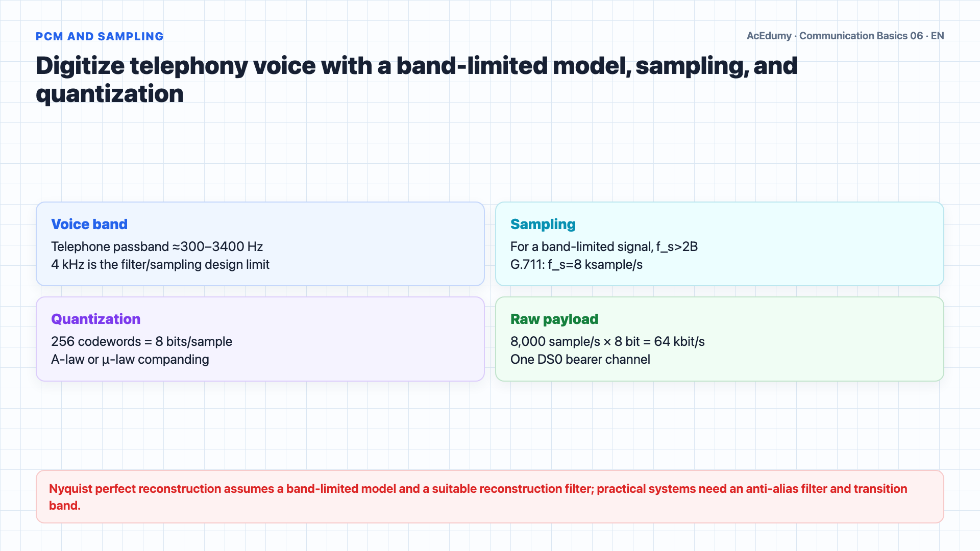
Build telephony PCM with the scope of Nyquist sampling and G.711. In synchronous TDM, separate payload, time slots, framing, and signaling; audit units in the E1/T1/J1 and video examples.
Written solution and narration transcript(shows the full solution)
Below are all the lines written in the notebook together with the full narration transcript.
1. Build the PCM sampling and quantization calculation
PCM payload, TDM time slots, and historical-carrier overhead are kept distinct in one consistent calculation. Before we can multiplex voice channels onto a digital link, we first need to convert analog voice into digital form.The telephony passband is approximately 300–3400 Hz; 4 kHz is a filter/sampling design limit, not the universal spectrum of human voice.Digital communication, however, uses discrete bits — zeros and ones.So we need a way to convert between the two.Analog to digital conversion is done by sampling the sound wave and representing each sample as a number.The Nyquist result assumes a band-limited signal and suitable reconstruction filter; 2B is the theoretical boundary, while practical anti-alias transition bands use fs>2B.For voice at 4 kilohertz, that means 2 times 4,000 equals 8,000 samples per second.The most common method for encoding these samples is called PCM — Pulse Code Modulation.G.711 maps 8,000 samples/s through A-law or μ-law companding to one of 256 eight-bit codewords.So the bit rate for one voice channel is 8,000 samples per second times 8 bits per sample, which equals 64 kilobits per second.This 64 kilobits per second is the fundamental building block of digital telephony — it is called a DS-0 channel.VoIP may use G.711 PCM; G.729 is a separate speech codec, not a 'compressed PCM variant.'Narration transcript
Before we can multiplex voice channels onto a digital link, we first need to convert analog voice into digital form. Human voice is a continuous analog signal in the range of 0 to 4 kilohertz. Digital communication, however, uses discrete bits — zeros and ones. So we need a way to convert between the two. Analog to digital conversion is done by sampling the sound wave and representing each sample as a number. According to the Nyquist sampling theorem, we need at least twice the maximum frequency to perfectly reconstruct the signal. For voice at 4 kilohertz, that means 2 times 4,000 equals 8,000 samples per second. The most common method for encoding these samples is called PCM — Pulse Code Modulation. In PCM, each sample is quantized into one of 256 levels, which requires 8 bits per sample. So the bit rate for one voice channel is 8,000 samples per second times 8 bits per sample, which equals 64 kilobits per second. This 64 kilobits per second is the fundamental building block of digital telephony — it is called a DS-0 channel. PCM remains the foundation of voice digitization today, and even modern Voice over IP systems use PCM or its compressed variants like G.711 and G.729.
2. Separate the synchronous TDM frame from payload
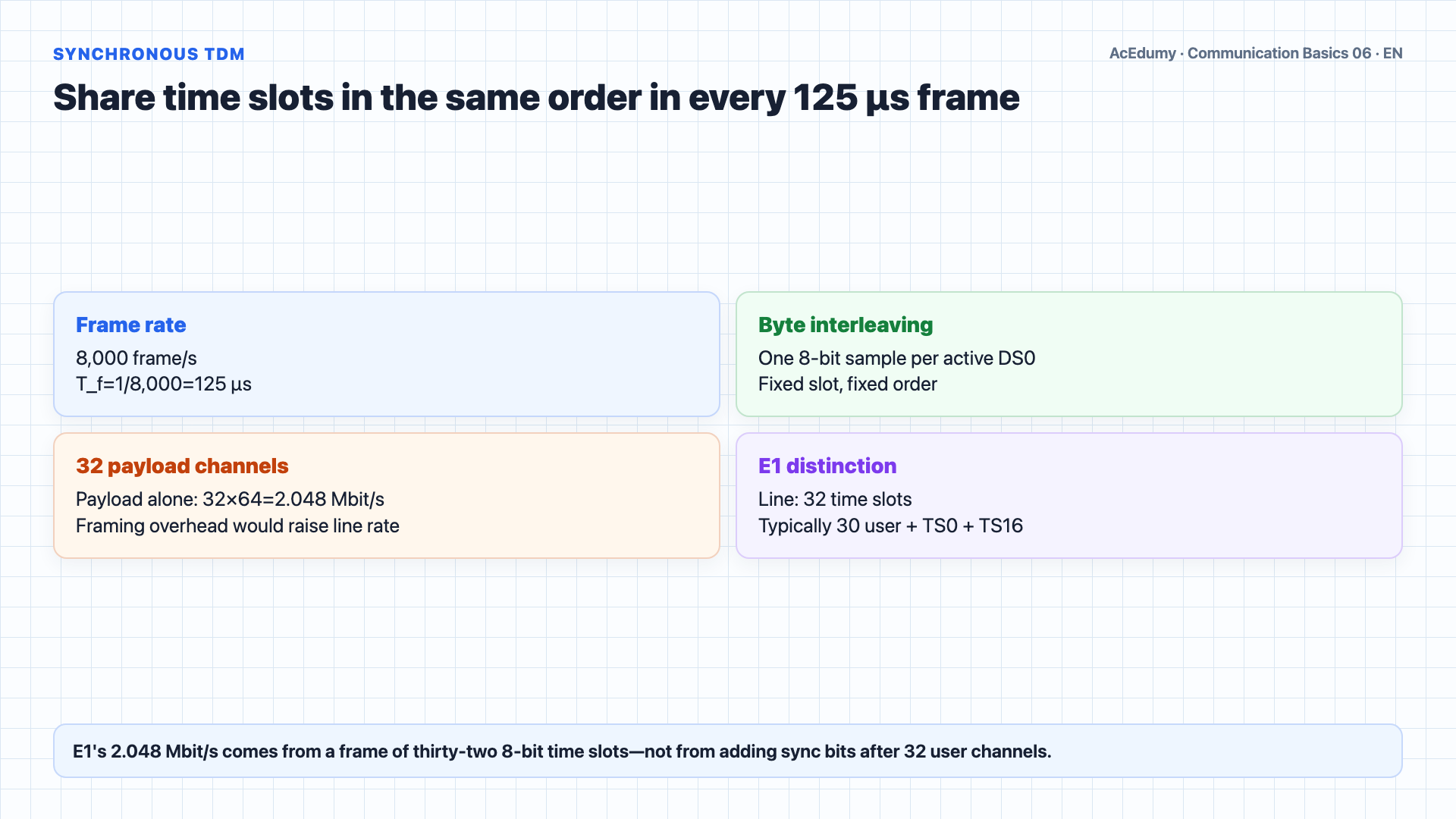
PCM payload, TDM time slots, and historical-carrier overhead are kept distinct in one consistent calculation. Now that we have digital voice channels at 64 kilobits per second each, how do we send many of them over a single transmission line?Installing a separate line for every channel is clearly not practical.The solution is multiplexing — sending many channels over one line.Time Division Multiplexing, or TDM, achieves this by giving each channel a fixed time slot.The multiplexer takes one byte — 8 bits — from each channel in sequence, and sends them one after another on the output line.After collecting one byte from every channel, it starts over with the next byte.This is called byte interleaving.The bare payload of 32 user channels is 32×64=2.048 Mbit/s; adding separate framing would require a line rate above that value.The multiplexer has only 1 over 8,000 seconds — that is 125 microseconds — to collect and send one byte from all 32 channels before the next sample arrives.But how does the receiving end know which byte belongs to which channel?This is solved by synchronization.Synchronous TDM marks frame boundaries with a framing pattern or reserved time slot; in E1, TS0 is inside the thirty-two-slot frame.The demultiplexer reads these sync bits and distributes the following bytes to the correct channels.Narration transcript
Now that we have digital voice channels at 64 kilobits per second each, how do we send many of them over a single transmission line? Installing a separate line for every channel is clearly not practical. The solution is multiplexing — sending many channels over one line. Time Division Multiplexing, or TDM, achieves this by giving each channel a fixed time slot. The multiplexer takes one byte — 8 bits — from each channel in sequence, and sends them one after another on the output line. After collecting one byte from every channel, it starts over with the next byte. This is called byte interleaving. For example, with 32 channels, each at 64 kilobits per second, the output rate must be at least 32 times 64, which equals 2,048 kilobits per second, or about 2 megabits per second. The multiplexer has only 1 over 8,000 seconds — that is 125 microseconds — to collect and send one byte from all 32 channels before the next sample arrives. But how does the receiving end know which byte belongs to which channel? This is solved by synchronization. Special synchronization bits are inserted into the frame to mark where each group of 32 bytes begins. The demultiplexer reads these sync bits and distributes the following bytes to the correct channels.
3. Scope E1, T1/J1, and the PDH hierarchy
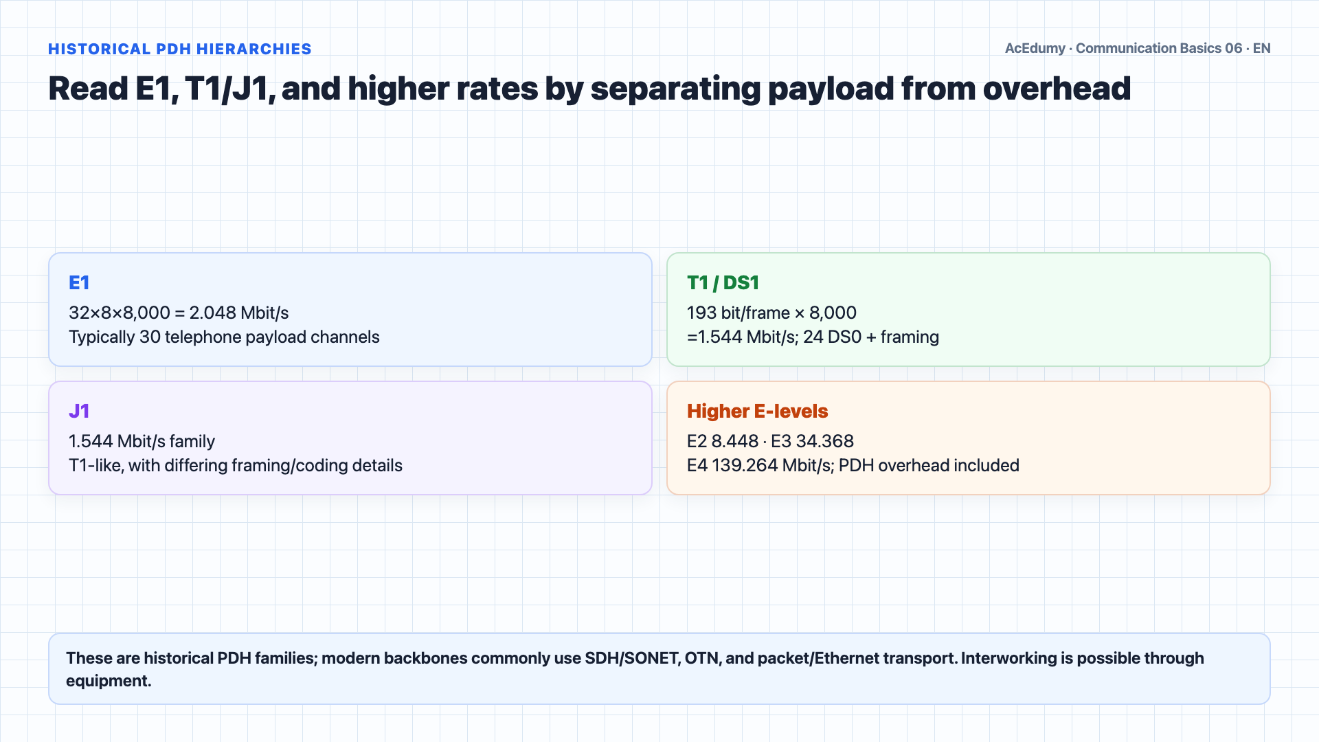
PCM payload, TDM time slots, and historical-carrier overhead are kept distinct in one consistent calculation. Different regions of the world developed their own TDM carrier standards.All three start with the same basic channel rate of 64 kilobits per second, but they differ in how channels are grouped.The European standard, called CEPT or E-Carrier, uses E-1 as its first level.An E1 frame has 32 time slots: TS0 carries framing, and TS16 may carry channel-associated signaling; typical telephony payload is 30 DS0 at a 2.048 Mbit/s line rate.The North American standard, called T-Carrier, uses T-1 or DS-1 as its first level.T1/DS1 sends a 193-bit frame—24×8=192 payload bits plus one framing bit—at 8 kframe/s, giving 1.544 Mbit/s; robbed-bit signaling is a separate payload detail.J1 belongs to the 24-channel, 1.544 Mbit/s family; its framing and line-coding details should not be assumed identical to T1.These first-level signals are then multiplexed into higher levels.E-2 combines 4 E-1 streams into 8.448 megabits per second with 120 channels.E-3 reaches 34.368 megabits per second with 480 channels.E-4 carries 139.264 megabits per second with 1,920 channels.The E5 label and upper-level rate must be checked against the cited national table; common historical European PDH interfaces are normally presented through E1–E4.These historical PDH families do not share direct framing and coding, but interworking is possible through conversion equipment.Narration transcript
Different regions of the world developed their own TDM carrier standards. All three start with the same basic channel rate of 64 kilobits per second, but they differ in how channels are grouped. The European standard, called CEPT or E-Carrier, uses E-1 as its first level. E-1 has 32 channels: 30 for user data and 2 for frame synchronization and signaling, giving a total rate of 2.048 megabits per second. The North American standard, called T-Carrier, uses T-1 or DS-1 as its first level. T-1 has 24 user channels plus 8 kilobits per second for signaling, giving 1.544 megabits per second. The Japanese J-Carrier mirrors T-1 at 1.544 megabits per second with 24 channels. These first-level signals are then multiplexed into higher levels. E-2 combines 4 E-1 streams into 8.448 megabits per second with 120 channels. E-3 reaches 34.368 megabits per second with 480 channels. E-4 carries 139.264 megabits per second with 1,920 channels. And E-5 reaches 565.148 megabits per second with 7,680 channels. Although all three systems share the same 64 kilobits per second base rate, they are incompatible with each other due to different framing and encoding methods.
4. Audit the telephony and historical-TV PCM examples
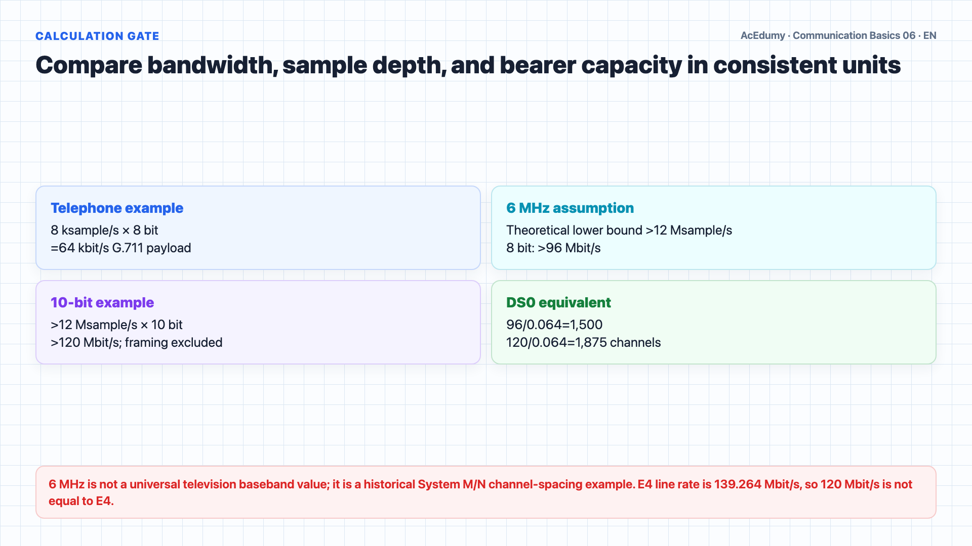
PCM payload, TDM time slots, and historical-carrier overhead are kept distinct in one consistent calculation. Let us work through two examples to solidify the PCM calculation.Example one: digitizing a standard telephone voice channel.We start with the voice bandwidth of 4 kilohertz.Applying the Nyquist theorem, the sampling rate is 2 times 4,000 hertz, which equals 8,000 samples per second.With PCM using 8 bits per sample for 256 quantization levels, the bit rate is 8,000 times 8, which equals 64,000 bits per second, or 64 kilobits per second.This is one DS-0 channel — the standard digital voice rate.Example two: digitizing a commercial television signal.Six megahertz is not a universal television baseband value; it is a historical System M/N channel-spacing assumption.For a band-limited 6 MHz assumption, 12 Msample/s is the theoretical boundary; a practical anti-alias design samples above 12 Msample/s.If we use 8 bits per sample, the bit rate is 12 million times 8, which equals 96 megabits per second.With 10 bits per sample for higher quality, it becomes 120 megabits per second.120 Mbit/s is not equal to the 139.264 Mbit/s E4 line rate; the bare ratio is 120/0.064=1,875 DS0, before framing and transport overhead.Narration transcript
Let us work through two examples to solidify the PCM calculation. Example one: digitizing a standard telephone voice channel. We start with the voice bandwidth of 4 kilohertz. Applying the Nyquist theorem, the sampling rate is 2 times 4,000 hertz, which equals 8,000 samples per second. With PCM using 8 bits per sample for 256 quantization levels, the bit rate is 8,000 times 8, which equals 64,000 bits per second, or 64 kilobits per second. This is one DS-0 channel — the standard digital voice rate. Example two: digitizing a commercial television signal. A TV video signal has a bandwidth of about 6 megahertz. The sampling rate would be 2 times 6 million, which equals 12 million samples per second. If we use 8 bits per sample, the bit rate is 12 million times 8, which equals 96 megabits per second. With 10 bits per sample for higher quality, it becomes 120 megabits per second. This is equivalent to an E-4 carrier — a single television channel requires the capacity of 1,920 voice channels.
5. Summarize PCM, TDM, framing, and codec scope
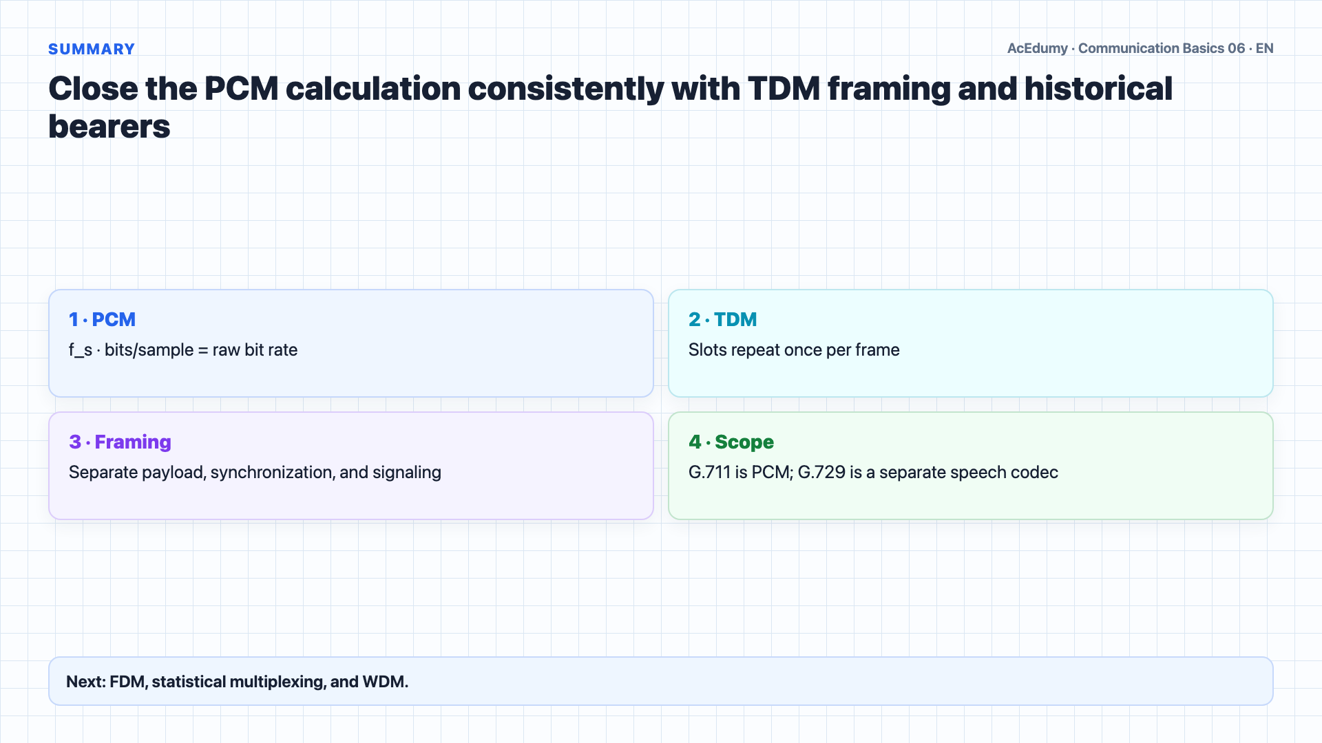
PCM payload, TDM time slots, and historical-carrier overhead are kept distinct in one consistent calculation. Let us review.PCM — Pulse Code Modulation — converts analog voice to digital by sampling at 8,000 times per second and encoding each sample with 8 bits, producing the standard 64 kilobits per second voice channel.TDM — Time Division Multiplexing — combines multiple 64 kilobits per second channels by interleaving one byte from each channel in sequence.Synchronization bits mark frame boundaries so the receiver knows which byte belongs to which channel.These are three historical PDH families: E1 has 32 time slots and typically 30 telephony payloads, while T1/J1 carry 24 DS0. Modern backbones also use SDH/SONET, OTN, and packet transport.These hierarchies scale up to thousands of channels at hundreds of megabits per second.In the next lesson, we will cover Frequency Division Multiplexing, Statistical Multiplexing, and Wavelength Division Multiplexing for fiber optics.Narration transcript
Let us review. PCM — Pulse Code Modulation — converts analog voice to digital by sampling at 8,000 times per second and encoding each sample with 8 bits, producing the standard 64 kilobits per second voice channel. TDM — Time Division Multiplexing — combines multiple 64 kilobits per second channels by interleaving one byte from each channel in sequence. Synchronization bits mark frame boundaries so the receiver knows which byte belongs to which channel. Three carrier standards exist: E-Carrier in Europe with 32-channel E-1 at 2.048 megabits per second, T-Carrier in North America with 24-channel T-1 at 1.544 megabits per second, and J-Carrier in Japan. These hierarchies scale up to thousands of channels at hundreds of megabits per second. In the next lesson, we will cover Frequency Division Multiplexing, Statistical Multiplexing, and Wavelength Division Multiplexing for fiber optics.
Source video: Communication Basics #06 PCM & Time Division Multiplexing (7:09)