Communication Basics · PSTN Infrastructure, SS7, and Tandem Dimensioning
#16 Historical PSTN access and class hierarchy, G.711 context, SS7/MTP/ISUP roles, trunk-group counting, traffic dimensioning, and NGN migration
Analyze PSTN infrastructure through access, codecs, historical hierarchy, common-channel signalling, traffic dimensioning, and NGN interworking—not a nostalgic block diagram.
Question
Separate PSTN access, codec, and core transport; bound the five-class hierarchy as a historical North American model; place SS7, MTP, ISUP, SSP, STP, and SCP at their proper roles; distinguish full-mesh and tandem trunk-group count from capacity, blocking, and redundancy; validate current packet-voice/NGN migration with measurable gates.
Written solution and narration transcript(shows the full solution)
Below are all the lines written in the notebook together with the full narration transcript.
1. Separate PSTN access, CPE, G.711, and core transport into their proper layers
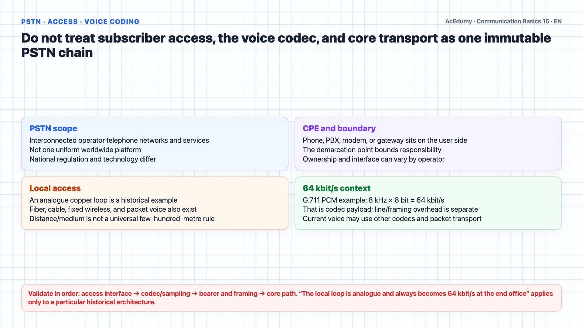
Access, codec, transport, signaling, and traffic dimensioning are separate layers; historical PSTN classes are not the universal topology of a current voice network. Welcome back.In the previous lesson we compared circuit switching with packet switching.We saw that the traditional telephone network — the PSTN — is the classic example of circuit switching.Today we open the hood of that network and look at how it is actually built.PSTN stands for Public Switched Telephone Network.PSTN is a family of interoperating public telephone networks and services under national/operator boundaries—not one uniform worldwide platform.Many current voice services use packet cores; historical TDM-PSTN remains a useful reference for hierarchical, circuit-switched narrowband design.Subscriber access commonly enters through CPE and a demarcation point, while a call may terminate at a network service, gateway, or another access technology.CPE is the gear sitting at the user side of the network: the telephone handset, the answering machine, the analog modem, the PBX in an office.A twisted-pair local loop is a historical access example; fiber, cable, fixed wireless, and packet-voice gateways can also connect the subscriber.Copper-loop length depends on service, wire gauge, cabinets/remote units, and operator design; there is no universal metre-to-kilometre range.A classic POTS copper loop can carry analogue voice; historical digital exchanges use G.711 PCM at 8 kHz × 8 bit = 64 kbit/s, while current access/codecs may differ.A 64 kbit/s DS0/G.711 channel is a base unit of historical digital PSTN multiplexing—not total line rate or a universal current voice bearer.Historical PDH/SDH transport multiplexes 64 kbit/s channels; signalling, framing, and current packet cores are separate functions.Narration transcript
Welcome back. In the previous lesson we compared circuit switching with packet switching. We saw that the traditional telephone network — the P S T N — is the classic example of circuit switching. Today we open the hood of that network and look at how it is actually built. P S T N stands for Public Switched Telephone Network. It is the worldwide collection of interconnected voice oriented public telephone networks. Although today most voice traffic rides on packet networks, the P S T N is still the textbook blueprint for understanding hierarchical, circuit switched, narrowband communication. Every P S T N call begins and ends at customer premises equipment, called C P E. C P E is the gear sitting at the user side of the network: the telephone handset, the answering machine, the analog modem, the P B X in an office. From the C P E a single twisted pair, called the local loop, runs all the way to the nearest end office of the telephone company. This local loop is typically a few hundred meters to a few kilometers long. It carries an analog voice signal that, inside the end office, is digitized into a 64 kilobit per second P C M channel. 64 kilobits per second is the fundamental currency of the P S T N. Everything above this layer is built by grouping these channels together.
2. Bound the five-class switching hierarchy by its historical and regional scope
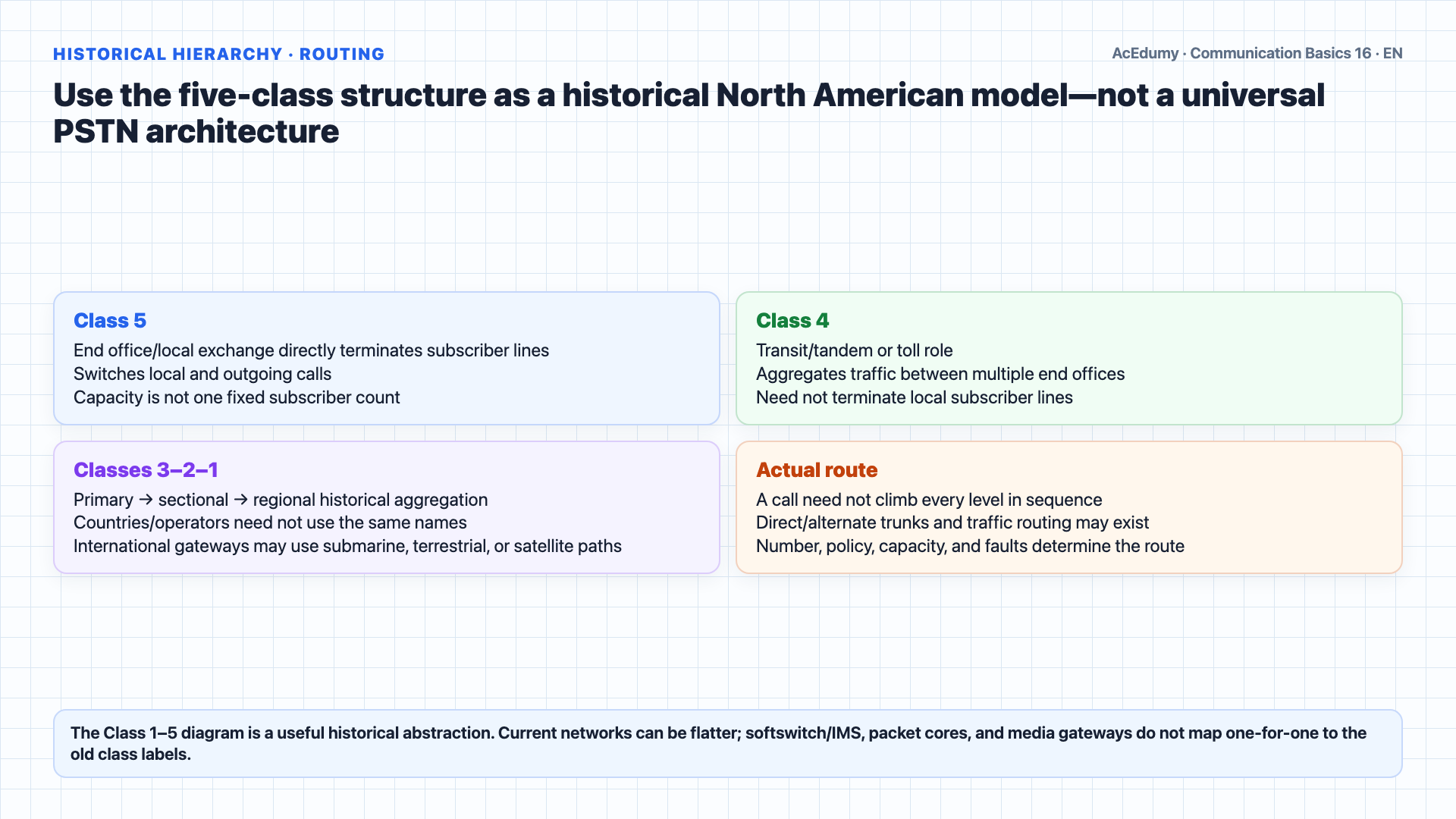
Access, codec, transport, signaling, and traffic dimensioning are separate layers; historical PSTN classes are not the universal topology of a current voice network. Now let us climb the hierarchy.The historical North American Bell System model used Class 1–5 switching layers; that classification is not universal across countries or current networks.Class five is at the bottom.It is the end office, also called the local exchange.In classic fixed access, the serving end office or an attached remote line unit is associated with the local loop; ownership varies by operator arrangement.A subscriber line may terminate at the end office or an attached remote access unit; current access architectures differ.End-office capacity varies by era, switch technology, remote line units, and operator design; it is not one fixed subscriber range.Class 4 historically describes a toll/transit or tandem switching role; terminology and implementation vary.It collects traffic from many end offices in the same area and switches inter exchange calls.Class three is the primary center.It aggregates several toll centers and provides regional switching for long distance calls.Class two is the sectional center.It interconnects primary centers across a wider area.Class one, at the top, is the regional center.Class 1 regional centers formed the top of that historical hierarchy; their count varied by period and network plan.Top-tier centers could be richly interconnected for resilience and alternate routing; do not assume an unconditional full mesh for every period or operator.The hierarchy provides a tree-like aggregation model; direct trunks and alternate routes can change the actual topology.A local call may stay entirely inside one Class five office.An inter-exchange call may use a direct trunk, tandem, or alternate route; it need not always rise to Class 4.A historical long-distance route could use several aggregation layers; the actual path follows direct trunks, policy, capacity, and failures.Hierarchy can aggregate traffic onto fewer high-capacity trunks; group capacity follows the demand matrix and blocking target.An international gateway interconnects operator/country networks through submarine, terrestrial fiber, microwave, or satellite paths.Current networks may flatten the old class hierarchy; packet cores, softswitch/IMS, and gateways aggregate traffic according to service, capacity, and resilience objectives.Narration transcript
Now let us climb the hierarchy. The classical North American P S T N was organized into five levels of switching offices, called Class one through Class five. Class five is at the bottom. It is the end office, also called the local exchange. This is the office that owns your local loop. Every subscriber line terminates here. A typical end office serves a few thousand to a few tens of thousands of subscribers. Class four is the toll center. It collects traffic from many end offices in the same area and switches inter exchange calls. Class three is the primary center. It aggregates several toll centers and provides regional switching for long distance calls. Class two is the sectional center. It interconnects primary centers across a wider area. Class one, at the top, is the regional center. There were only a handful of these in the entire country. Class one centers were fully meshed with each other to provide nationwide coverage. The traffic flows like a tree. A local call may stay entirely inside one Class five office. A call across town goes Class five up to Class four and back down. A long distance call may climb several levels before coming back down on the far side. Each step up the hierarchy aggregates more traffic onto fewer, fatter trunks. Above the regional center sits the international gateway, which connects one country's P S T N to another country's P S T N through submarine cables or satellites. Modern networks have flattened this hierarchy, but the same logic still applies: concentrate traffic, multiplex it, and switch it as high in the tree as needed.
3. Map switching/transport roles to SS7, MTP, ISUP, SSP, STP, and SCP functions
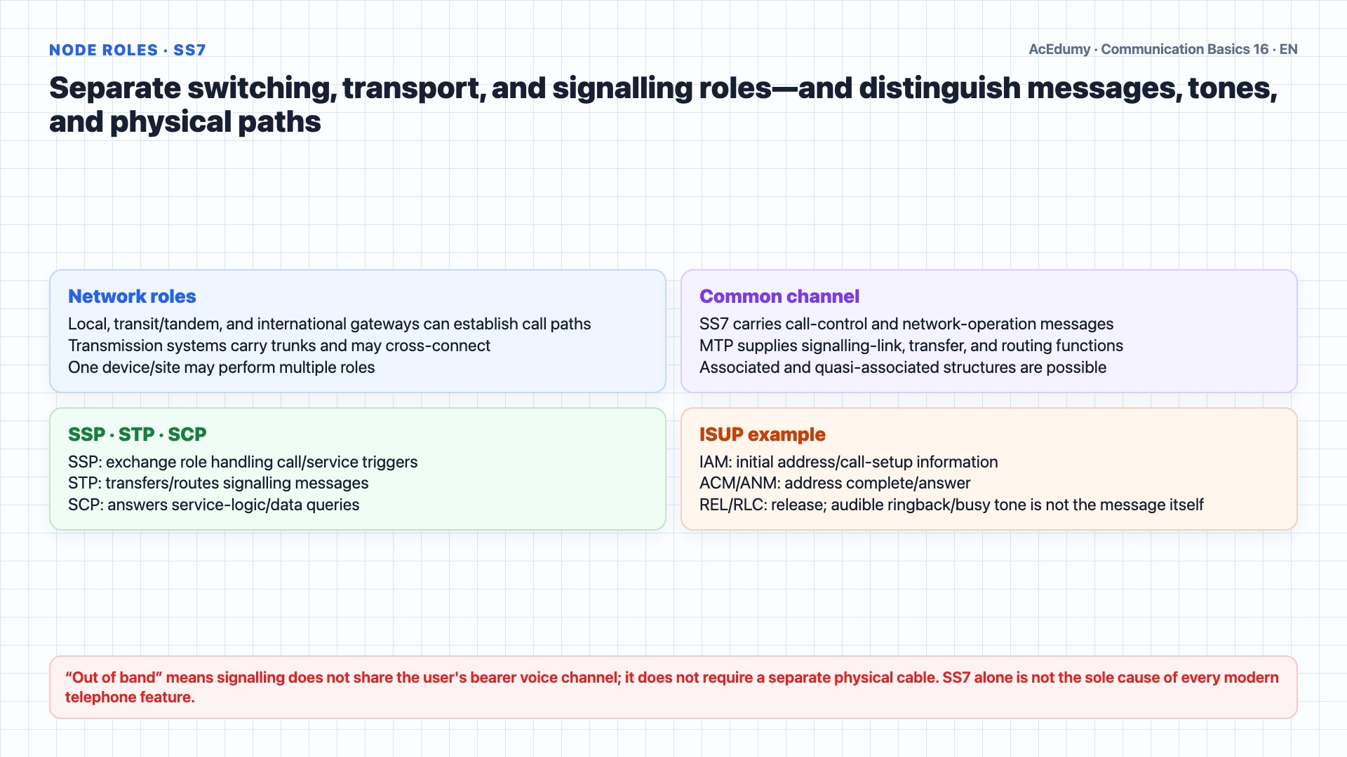
Access, codec, transport, signaling, and traffic dimensioning are separate layers; historical PSTN classes are not the universal topology of a current voice network. Switching, transport, and service-control are useful functional roles; they may coexist in one device/site and are not a universal three-physical-node taxonomy.In the historical circuit model, exchanges perform the switching role; current networks may separate control and media functions.This role connects the bearer path selected by call control; all call logic need not reside in one device.There are several flavors.The local exchange terminates subscriber loops and switches calls between local subscribers.A tandem/transit role carries inter-exchange traffic and typically does not directly terminate subscriber access; combined exchanges may perform multiple roles.A toll/transit exchange historically carried longer-distance or inter-area traffic; naming and scope vary by network.And the international gateway exchange is the door to other countries.Transport systems carry bearer/trunk capacity and may cross-connect traffic, while call control remains a separate function.Their job is to carry the aggregated traffic between switching offices on high capacity trunks.Trunk media have used copper, coaxial, microwave, satellite, and fiber in overlapping orders that vary by era and geography.Historical digital transport sites may contain multiplexers, regenerators, and cross-connects; E-carrier and T-carrier are distinct regional framing/rate hierarchies.SCPs and service platforms supply particular service logic/data; routing, call control, and billing are not one centralized 'brain' role.Service platforms may supply data or logic for particular queries; call decisions can be distributed across exchanges, control functions, and service platforms.Forwarding/routing data can reside in switches and signalling points, while service profiles, toll-free, or portability data may reside in the relevant SCP/database platforms.SS7 carries common-channel messages among particular signalling points; not every transport or service node must be a direct SS7 point.SS7 is out of band signaling.ISUP carries call setup, progress, answer, and release information in messages such as IAM, ACM, ANM, and REL/RLC; audible ringback or busy tone is not itself the message.Messages use logical signalling links/network separate from the bearer voice channel; the physical plant need not be wholly separate.An SSP is an exchange role that handles call/service triggers; not every SS7 signalling point is an SSP.An STP transfers/routes messages in a quasi-associated SS7 structure; associated signalling can also run directly between signalling points.An SCP answers particular service-logic/data queries; not every network database is automatically an SCP.SS7/IN can support call control and services such as caller identity, forwarding, and toll-free routing; access protocols and service platforms are also part of the result.Narration transcript
Inside this hierarchy you will find three different kinds of nodes: switching nodes, transmission nodes, and service nodes. Switching nodes are the actual exchanges. Their job is to set up the path for each call. There are several flavors. The local exchange terminates subscriber loops and switches calls between local subscribers. The tandem exchange does no subscriber termination at all; it sits between local exchanges and forwards calls between them. The toll exchange handles inter city traffic. And the international gateway exchange is the door to other countries. Transmission nodes do not switch calls. Their job is to carry the aggregated traffic between switching offices on high capacity trunks. These trunks were historically twisted pair, then coaxial cable, then microwave, and finally fiber optic. Inside a transmission node you will find multiplexers, regenerators, and cross connects that combine many 64 kilobit per second channels into the E carrier or T carrier hierarchy we will study in the next lesson. Service nodes are the brain of the network. They are the databases and signaling controllers that decide what to do with a call. They store routing tables, billing information, subscriber profiles, toll free numbers, and number portability data. All three node types are tied together by a special signaling network called S S 7, Signaling System Number Seven. S S 7 is out of band signaling. That means the signaling messages — dialed digits, ring requests, busy tones, hang up — do not travel on the same channel as the voice. They travel on a separate packet network that connects all the switching offices. The endpoints of S S 7 are called Service Switching Points, or S S Ps. S S 7 packets are routed by Signal Transfer Points, or S T Ps. And the databases I just mentioned are called Service Control Points, or S C Ps. Out of band signaling is what allows modern P S T N features like caller I D, call forwarding, three way calling, and toll free numbers.
4. Dimension full-mesh and tandem connectivity with traffic capacity, blocking, and resilience
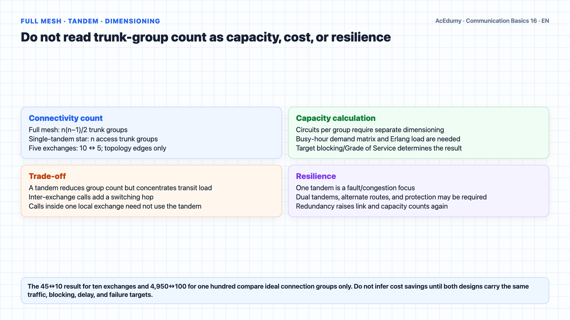
Access, codec, transport, signaling, and traffic dimensioning are separate layers; historical PSTN classes are not the universal topology of a current voice network. Let us work through a classic problem that shows why the hierarchy exists in the first place.Imagine a small region with five local exchanges.Call them A, B, C, D, and E.We want any subscriber on any exchange to be able to call any other subscriber.Approach one: full mesh.Connect every exchange directly to every other exchange.How many trunk groups do we need?Each exchange must connect to the other four, but each connection is shared between two exchanges, so we count it once.The formula is n times n minus one divided by two.For n equal to five, that gives five times four divided by two, which equals ten trunk groups.Approach two: tandem.Place one tandem exchange in the middle and connect each local exchange to the tandem with a single trunk group.The tandem switches calls between any two locals.How many trunk groups now?Just five, one per local exchange.In the ideal connectivity graph, full mesh has 10 and a single-tandem star has 5 trunk groups; circuits per group require separate dimensioning.For n=5 the tandem halves trunk-group count; it does not halve carried circuits, busy-hour load, or blocking by definition.And as the network grows, the difference becomes much larger.For n=10 the connectivity count is 45 versus 10; capacity, redundancy, and alternate routes are excluded.For n=100 the ideal connectivity count is 4,950 versus 100; that is neither circuit capacity nor total cost.A tandem design trades fewer groups for transit capacity, switching, operations, and redundancy requirements.An inter-exchange call may add a tandem hop; a call inside one local exchange need not. One unprotected tandem can become a failure/congestion focus.Economics follow busy-hour capacity, distance, ports, sites, operations, and redundancy—not connectivity count alone.Hierarchy supported trunk economics, scalable routing, and operations by aggregating traffic; capacity, blocking, and resilience still had to be designed together.Narration transcript
Let us work through a classic problem that shows why the hierarchy exists in the first place. Imagine a small region with five local exchanges. Call them A, B, C, D, and E. We want any subscriber on any exchange to be able to call any other subscriber. Approach one: full mesh. Connect every exchange directly to every other exchange. How many trunk groups do we need? Each exchange must connect to the other four, but each connection is shared between two exchanges, so we count it once. The formula is n times n minus one divided by two. For n equal to five, that gives five times four divided by two, which equals ten trunk groups. Approach two: tandem. Place one tandem exchange in the middle and connect each local exchange to the tandem with a single trunk group. The tandem switches calls between any two locals. How many trunk groups now? Just five, one per local exchange. Compare: ten trunks for full mesh versus five trunks for tandem. The tandem cuts the number of trunks in half. And as the network grows, the difference becomes much larger. With ten exchanges, full mesh needs forty five trunk groups, but tandem needs only ten. With one hundred exchanges, full mesh needs four thousand nine hundred fifty, while tandem needs only one hundred. Of course tandem is not free. Every call now passes through one extra switch, which adds delay, equipment cost, and a single point of congestion. But the savings on trunk infrastructure are enormous, especially over long distances where the trunks themselves dominate the total cost. This is exactly why the P S T N hierarchy was invented: to push as much traffic as possible onto a small number of high capacity, well utilized trunks instead of a huge mesh of lightly used direct links.
5. Summarize historical PSTN to NGN/IMS packet voice through measurable quality gates
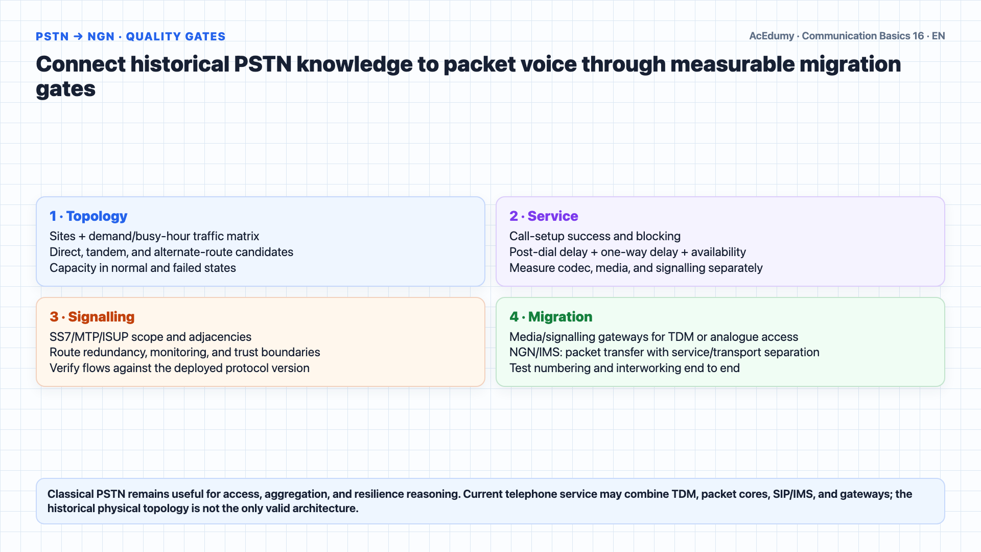
Access, codec, transport, signaling, and traffic dimensioning are separate layers; historical PSTN classes are not the universal topology of a current voice network. Let us summarize today's lesson.Historical digital TDM-PSTN is a hierarchical circuit-network model using 64 kbit/s G.711/DS0 channels; current telephone service can use packet cores and other codecs.A classic POTS call can travel from CPE over a copper local loop to a Class 5 end office; current access can be fiber, cable, wireless, or a packet gateway.The historical North American class model placed toll/transit, primary, sectional, and regional layers above the end office; this is not a universal current requirement.Switching, bearer transport, and service control are three functional roles; they may coexist, while routing, call control, service profiles, and billing data can be distributed across platforms.SS7 carries common-channel messages among SSPs, STPs, SCPs, and other signalling points; topology can be associated/quasi-associated and not every network node is an SS7 point.A single-tandem star grows trunk-group connectivity more slowly than a full mesh; actual circuit capacity, blocking, and redundancy require separate dimensioning.PDH multiplexes 64 kbit/s channels through distinct regional E-carrier and T-carrier framing/rate hierarchies; the next lesson will bound those details.Narration transcript
Let us summarize today's lesson. The P S T N is a hierarchical, circuit switched, narrowband public network built around 64 kilobit per second voice channels. Every call starts at customer premises equipment and travels over a local loop to the nearest end office, also known as the Class five exchange. Above the end office sit four more levels in the classical hierarchy: toll center, primary center, sectional center, and regional center. Inside this hierarchy three kinds of nodes work together: switching nodes that set up calls, transmission nodes that carry aggregated traffic on trunks, and service nodes that store routing and billing information. All of these nodes communicate over S S 7, a separate out of band packet signaling network with S S Ps, S T Ps, and S C Ps. Our worked example showed why the hierarchy exists: a tandem switch dramatically reduces the number of trunks compared to a full mesh, especially as the network grows. In the next lesson we will zoom in on the trunks themselves and study P D H, the Plesiochronous Digital Hierarchy, which is how those 64 kilobit channels get bundled into the E one and T one carrier systems that ride between the offices.
Source video: Communication Basics #16 PSTN Infrastructure: Hierarchy, Local Loop & SS7 (10:02)