Circuit Theory 1 · First-Order Transients
#44 Transient Analysis #44 — RL step response and RC/RL duality
Solves the RL step response with the initial-final-time-constant method, works a 10 V example, and compares RC/RL duality.
Question
An initially unenergized RL circuit with R=200 Ω, L=0.5 H, and V_S=10 V is connected at t=0. Find i_L(t), v_L(t), τ, and the currents at one, three, and five tau.
Written solution and narration transcript(shows the full solution)
Below are all the lines written in the notebook together with the full narration transcript.
1. RL circuit: initial, final, and tau
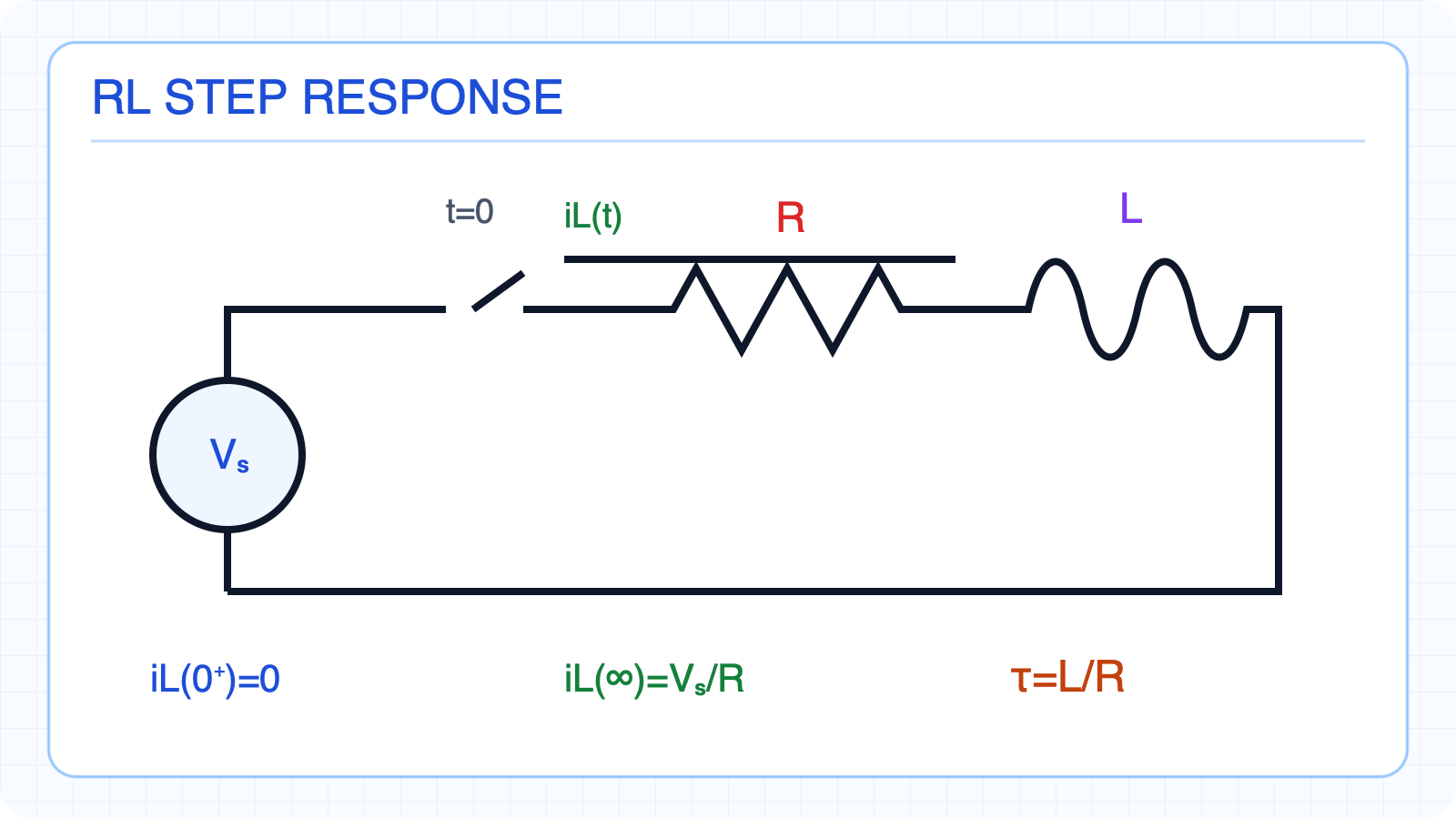
Current rises from zero to V_S/R with τ=L/R. The switch closes at t=0The inductor initially carries no currentAt DC steady state the inductor is a shortThe resistance seen by the inductor is RRC uses τ=RC; RL uses τ=L/RAll three values are readyNarration transcript
Now let us apply the step response formula to an R L circuit. We have a voltage source V S connected through a switch to a resistor R and an inductor L in series. The switch closes at t equals zero. Before switching, the inductor carries no current, so i L of zero equals zero. After a long time, the inductor acts as a short circuit and the current reaches its maximum steady state value: i L of infinity equals V S over R. The time constant for an R L circuit is tau equals L over R. Notice how this differs from R C circuits: for R C, tau equals R C, but for R L, tau equals L divided by R.
2. RL current rise and voltage decay
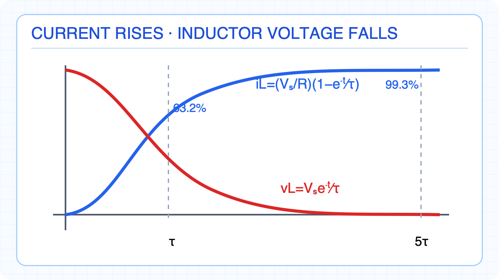
Current rises while inductor voltage decays exponentially. Apply the general formula with x=iLCurrent rises from zero to VS/RIt reaches 63.2 percent at one tauIt reaches 99.3 percent at five tauInductor voltage falls from VS to zeroCurrent rises while voltage fallsNarration transcript
Plugging into the general formula: i L of t equals V S over R plus the quantity zero minus V S over R times e to the negative t over tau. Simplifying, i L of t equals V S over R times the quantity one minus e to the negative t over tau, where tau equals L over R. The current starts at zero and rises exponentially toward V S over R. At t equals tau, i L reaches sixty three point two percent of V S over R. At five tau, it reaches ninety nine point three percent. The inductor voltage is: v L of t equals V S times e to the negative t over tau. The voltage starts at V S and decays exponentially to zero. Notice the pattern: in R L circuits, the current rises while the voltage across the inductor falls. This is the mirror image of R C charging, where the voltage rises and the current falls.
3. Numerical 10 V RL step example
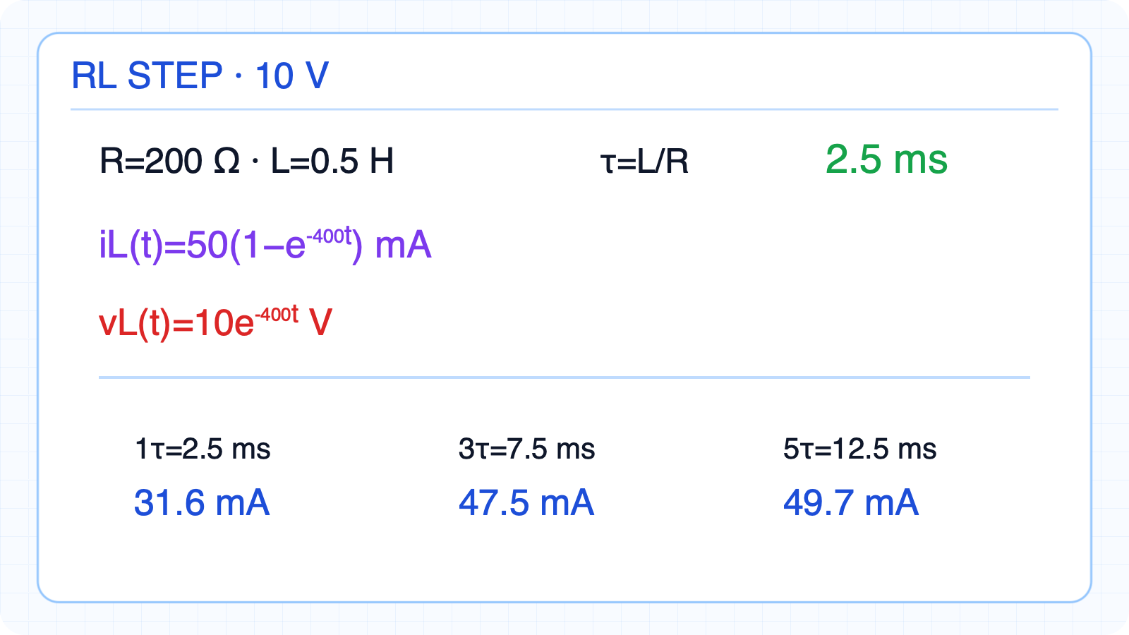
τ=2.5 ms and current values at one, three, and five tau. iL(∞)=50 mAτ=2.5 msiL(t)=50(1−e(−400t)) mAiL(τ)=31.6 mA; iL(3τ)=47.5 mAiL(5τ)=49.7 mANarration transcript
Let us work a numerical example. Given R equals two hundred ohms, L equals zero point five henrys, and V S equals ten volts. Step one: the initial condition is i L of zero equals zero amps, the inductor starts with no current. Step two: the final value is i L of infinity equals V S over R equals ten over two hundred, which is fifty milliamps. Step three: the time constant is tau equals L over R equals zero point five over two hundred, which equals two point five milliseconds. Now apply the formula: i L of t equals fifty milliamps times one minus e to the negative four hundred t. At t equals two point five milliseconds, that is one tau, i L equals fifty times zero point six three two, which is thirty one point six milliamps. At t equals seven point five milliseconds, three tau, i L equals forty seven point five milliamps. At t equals twelve point five milliseconds, five tau, i L equals forty nine point seven milliamps, essentially fifty.
4. RC and RL duality
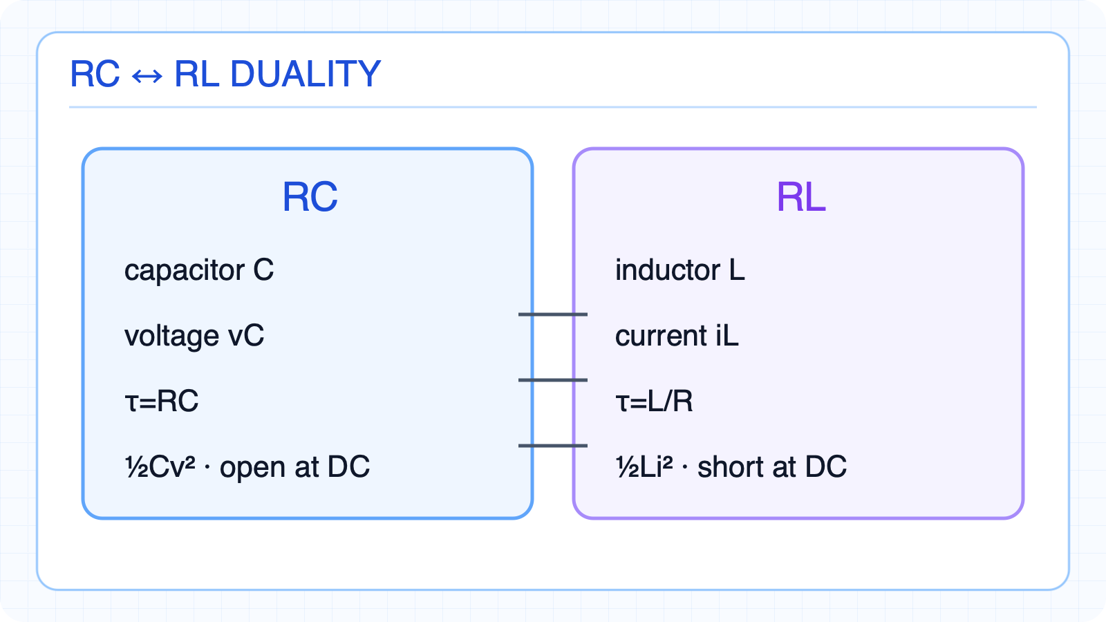
Storage element, variable, time constant, energy, and DC mappings. One general formula with dual variablesRC storage element: CRL storage element: LRC key variable vC; RL key variable iLRC: τ=RC ↔ RL: τ=L/RAt DC, C is open and L is shortCapacitor energy is ½Cv²Inductor energy is ½Li²Voltage and current roles correspondNarration transcript
Now let us compare R C and R L circuits side by side. This is called duality. The storage element in R C is the capacitor, while in R L it is the inductor. In R C the key variable is voltage V C, while in R L it is current i L. The time constant for R C is tau equals R C, while for R L it is tau equals L over R. In the charging equation, R C has V C of t equals V S times one minus e to the negative t over R C. R L has i L of t equals V S over R times one minus e to the negative t over tau. At steady state, a capacitor acts as an open circuit with zero current. An inductor acts as a short circuit with zero voltage across it. The energy stored: capacitor stores one half C V squared, inductor stores one half L i squared. Despite these differences, both follow the same general formula x of t equals x of infinity plus x of zero minus x of infinity times e to the negative t over tau.
5. Natural response and step response
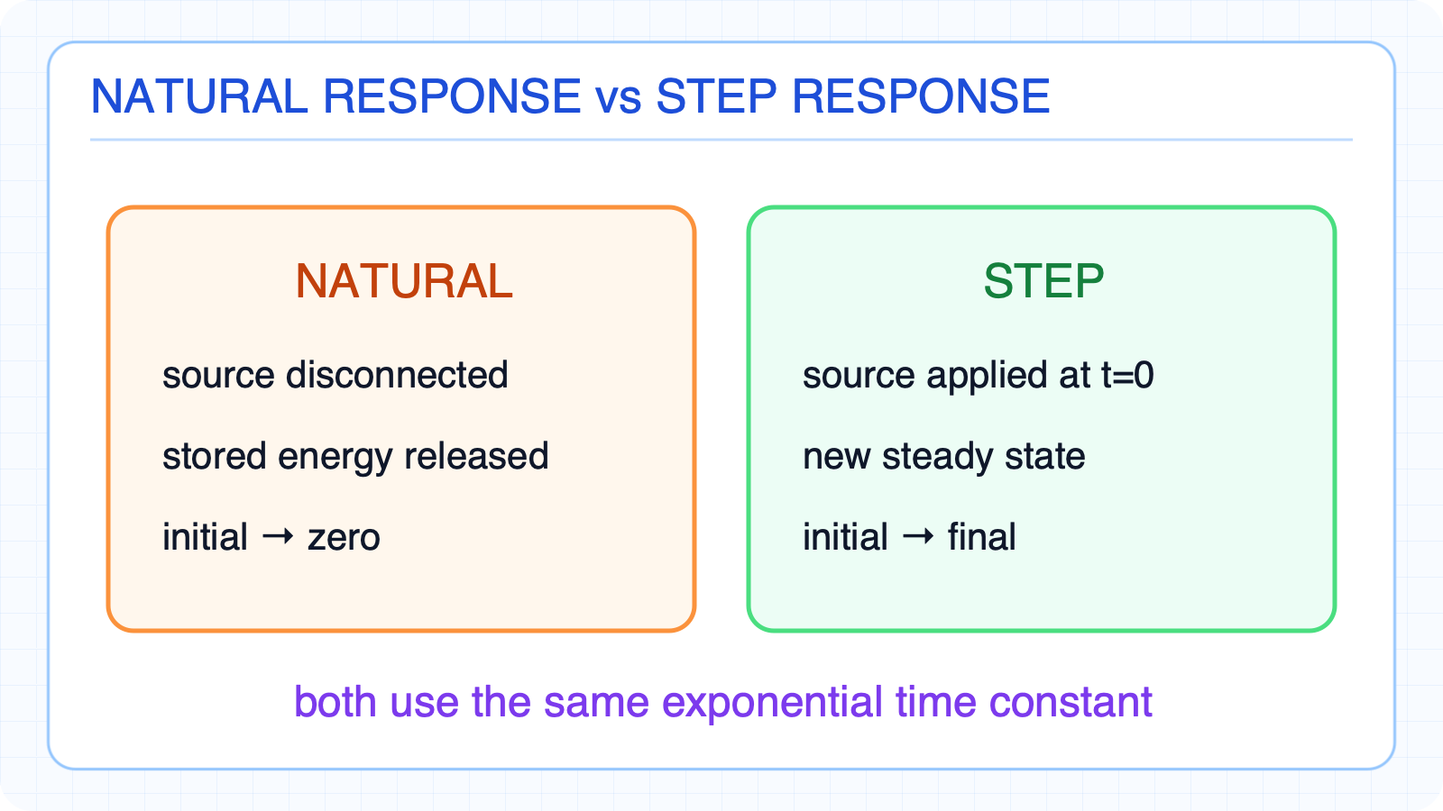
Both share the same exponential form with different endpoints. Both use the same exponential time scaleThe source is disconnected in natural responseStored energy is releasedNatural response: initial → zeroA source is applied at t=0 in step responseThe source establishes a new steady stateStep response: initial → finalNatural response needs initial value and tauStep response needs initial, final, and tauNarration transcript
Let us also clarify the difference between natural and step response. In the natural response, the source is disconnected and the circuit releases its stored energy. The response decays from an initial value to zero. In the step response, a source is suddenly applied. The response rises from an initial value toward a new steady state determined by the source. For natural response, we need only the initial condition and tau. For step response, we need initial, final, and tau. Both share the same exponential time constant behavior.
6. RL step-response checklist
Current rises while inductor voltage decays exponentially. Solve an RL step response with three values1) Find iL(0⁺)2) Find iL(∞)3) Find τ=L/ReqVerify the t=0 and t→∞ limitsUse RC/RL duality as a sign checkNext topic: sequential switchingNarration transcript
Let us summarize. The R L step response is: i L of t equals V S over R times one minus e to the negative t over tau, where tau equals L over R. Current rises from zero to V S over R while inductor voltage decays from V S to zero. The three step method works for both R C and R L circuits: find the initial value, find the final value, find tau, then substitute into the general formula. R C and R L circuits are duals of each other: capacitor maps to inductor, voltage maps to current, and R C maps to L over R. Next, we will study sequential switching, where circuits have multiple switching events at different times.