Circuit Theory 2 · RMS, complex power and power factor
#08 Distinguish RMS magnitudes, complex power and apparent power, then explain ideal shunt compensation
Use RMS for equivalent heating, keep real/reactive/apparent power distinct, and explain when ideal capacitive compensation reduces upstream current.
Question
Work with a single-phase lumped circuit in sinusoidal steady state at one nonzero frequency. Choose passive reference current into the voltage reference's positive terminal. The general root-mean-square definition averages the square over a full period; equal heating means equal average power in the same constant positive resistor. For zero-mean sinusoids only, RMS magnitude is nonnegative peak amplitude divided by sqrt(2); a DC offset or other waveform needs the full definition. Lowercase v(t) and i(t) are instantaneous real values. Uppercase V and I in S=V I* are complex RMS phasors, not scalar magnitudes; V_rms and I_rms are their nonnegative magnitudes. The star conjugates the current phasor, and j is the imaginary unit. Define φ as voltage phase minus current phase: positive for lagging inductive current, negative for leading capacitive current. Use S for complex power, P for cycle-average real power in watts, Q for reactive power in var, and |S| for apparent power in volt-amperes. P is net energy-transfer rate, including heat loss, not necessarily useful output or conversion efficiency; Q is not an amount of energy in joules. Complex power is not the sinusoidal phasor of instantaneous power. For an absorbing passive load and nonzero apparent power, power factor is P/|S|=cosφ in this sinusoidal model; distorted waveforms require a more general treatment. Compare current requirements at fixed nonzero RMS voltage and fixed positive real power. For compensation, add an ideal shunt capacitor across the unchanged inductive load at that fixed voltage and frequency. It supplies negative reactive power but does not change the load's real power in this ideal model. Select capacitance so the magnitude of net Q decreases; correction does not automatically mean leading current, and excessive capacitance can increase current again. Distinguish load current from total upstream current, and energy conversion efficiency from power factor. These are ideal circuit-model relationships, not installation instructions. Original narration/video remain unchanged. Cropped graphs, mixed S notation, a misplaced projection label and a leading-after-correction generalization are recorded for manual teaching/publication QA; this is an unpublished draft.
Written solution and narration transcript(shows the full solution)
Below are all the lines written in the notebook together with the full narration transcript.
1. Describe sinusoidal loading compactly
Original-video reference card, not a newly corrected graph. Four cropped or misleading graph scenes use this lesson's bridge, summary or compensation card. The notebook distinguishes RMS magnitudes, complex S, apparent |S| and power factor from conversion efficiency; compensation assumes fixed voltage and suitable sizing. Instantaneous power and cycle-average power describe different aspects of energy transfer.Use single-phase sinusoidal steady state, with passive current reference into the voltage reference's positive terminal.Root mean square (RMS), complex power and power factor give a compact description of the same waveforms.Keep instantaneous values, nonnegative RMS magnitudes and complex RMS phasors distinct.Narration transcript
Instantaneous and average power are not enough by themselves. We still need a compact way to describe voltage, current, and total loading in sinusoidal steady state. That is where RMS values, complex power, and power factor come in. Together, they compress the waveform story into a few highly useful numbers.
2. Compare RMS and equivalent DC heating
Original-video reference card, not a newly corrected graph. Four cropped or misleading graph scenes use this lesson's bridge, summary or compensation card. The notebook distinguishes RMS magnitudes, complex S, apparent |S| and power factor from conversion efficiency; compensation assumes fixed voltage and suitable sizing. Square, average over a period, then take the square root:The same constant positive resistor has the same average heating with this DC voltage magnitude:For a zero-mean sine wave with nonnegative peak amplitude:For a DC offset or a different waveform, use the full RMS definition; peak divided by sqrt(2) is not a universal rule.Narration transcript
RMS means root mean square, but the physical idea is more important than the name. The RMS value of an AC waveform is the DC value that would produce the same heating effect in a resistor. For a sine wave, that is the peak value divided by square root of two. So RMS is really the effective value for power calculations.
3. Separate real, reactive and apparent power
Original-video reference card, not a newly corrected graph. Four cropped or misleading graph scenes use this lesson's bridge, summary or compensation card. The notebook distinguishes RMS magnitudes, complex S, apparent |S| and power factor from conversion efficiency; compensation assumes fixed voltage and suitable sizing. Use P in watts, Q in var and apparent power |S| in volt-amperes (VA).Real power includes heat loss, not only useful output. With φ equal to voltage phase minus current phase:Reactive power describes field exchange, not energy measured in joules:Apparent power is the nonnegative magnitude, not the complex number itself:Narration transcript
Now we separate power into three linked quantities. Real power P is the net useful power. Reactive power Q tracks the energy exchange with fields. Apparent power S combines both, and the power triangle ties them together geometrically.
4. Use complex power with RMS phasors
Original-video reference card, not a newly corrected graph. Four cropped or misleading graph scenes use this lesson's bridge, summary or compensation card. The notebook distinguishes RMS magnitudes, complex S, apparent |S| and power factor from conversion efficiency; compensation assumes fixed voltage and suitable sizing. Complex power combines the two signed components; j is the imaginary unit:Under passive references, inductive loads have positive Q and lagging current; capacitive loads have negative Q and leading current.Using complex RMS phasors, conjugate the current phasor:S has magnitude and angle in the complex-power plane; it is not the phasor of the instantaneous power waveform.Narration transcript
Complex power packages that triangle into one compact expression: S equals P plus j Q. The real axis carries real power, and the imaginary axis carries reactive power. So the vector S contains both magnitude and direction information. That is why complex power is so convenient in AC analysis.
5. Relate current alignment and power factor

Original-video reference card, not a newly corrected graph. Four cropped or misleading graph scenes use this lesson's bridge, summary or compensation card. The notebook distinguishes RMS magnitudes, complex S, apparent |S| and power factor from conversion efficiency; compensation assumes fixed voltage and suitable sizing. Define the phase difference using the voltage and current phasor angles:Power factor for an absorbing load with nonzero apparent power in this sinusoidal model:Power factor near one means a small quadrature current component; it is not the energy-conversion efficiency.At fixed nonzero RMS voltage and fixed positive real power, lower power factor requires more RMS current:Narration transcript
Power factor measures how well current aligns with voltage. It is the cosine of the phase angle between them. A power factor near one means most of the current contributes to real power. A lower power factor means more current is circulating just to support reactive exchange.
6. Compensate an inductive load without overcorrection

Original-video reference card, not a newly corrected graph. Four cropped or misleading graph scenes use this lesson's bridge, summary or compensation card. The notebook distinguishes RMS magnitudes, complex S, apparent |S| and power factor from conversion efficiency; compensation assumes fixed voltage and suitable sizing. Consider an ideal shunt capacitor across the unchanged inductive load at fixed RMS voltage and frequency.Its reactive power is negative; ω is angular frequency and C is capacitance:Size it so the magnitude of net reactive power decreases. The total seen upstream is:At fixed load voltage, ideal compensation does not change the load's real power or create extra real power.Overcorrection can make current lead and increase its magnitude again. Upstream current is:Narration transcript
This is why correction matters. If an inductive load pulls current too far away from the voltage phasor, we can add capacitive compensation. That reduces reactive power and pulls the current phasor back toward the voltage phasor. The goal is not magic. The goal is cleaner loading and a stronger power factor.
7. Keep RMS, complex power and power factor distinct
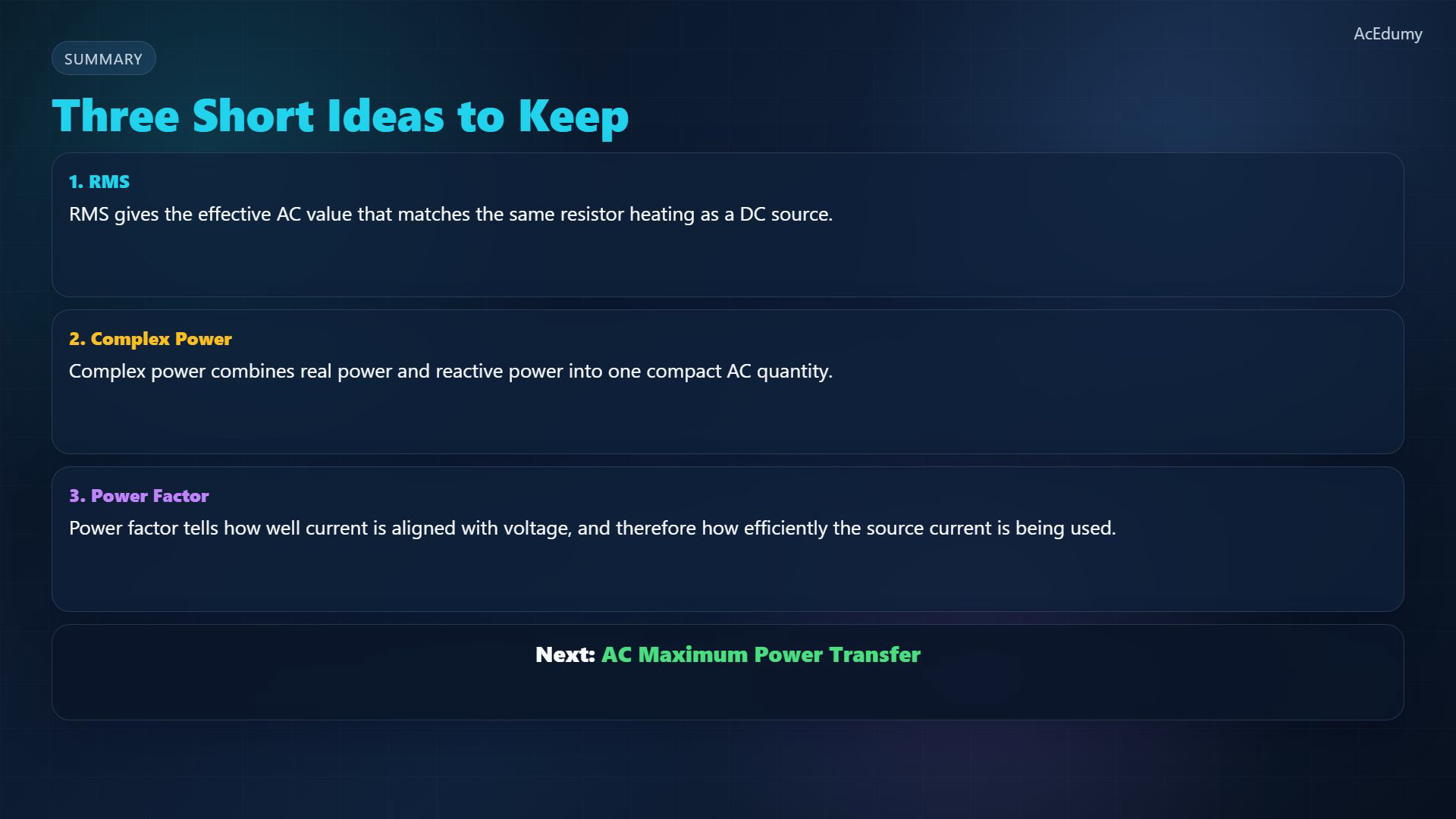
Original-video reference card, not a newly corrected graph. Four cropped or misleading graph scenes use this lesson's bridge, summary or compensation card. The notebook distinguishes RMS magnitudes, complex S, apparent |S| and power factor from conversion efficiency; compensation assumes fixed voltage and suitable sizing. For a zero-mean sinusoidal current, RMS is the effective heating magnitude:Keep complex S, apparent |S| and power factor separate; a high power factor does not prove high conversion efficiency.Next: alternating-current (AC) maximum power transfer.Narration transcript
RMS gives the effective voltage and current. Complex power combines real and reactive parts, and power factor tells us how well voltage and current are aligned. Next, we use those ideas in AC maximum power transfer.
Source video: Circuit Theory-2 #08 RMS, Complex Power, and Power Factor (2:38)