Circuit Theory 2 · s-Domain RLC models with initial conditions
#17 Unilateral Laplace branch equations, passive source polarities, and RC natural response
Keep zero-minus initial states and passive source signs in complete RLC equations, then solve an RC discharge with readable fractions.
Question
Derive the s-domain models of ideal linear constant-parameter R, L and C using the passive sign convention: current enters the positive voltage terminal. Use the zero-minus unilateral Laplace convention, including a possible origin impulse consistently, so the derivative transform subtracts the stored value at zero minus. Inductor V_L=sLI_L−Li_L(0−); capacitor I_C=C[sV_C−v_C(0−)], equivalently V_C=I_C/(sC)+v_C(0−)/s. R, sL and 1/(sC) are impedances in ohms; −Li_L(0−) and v_C(0−)/s are signed transformed voltage-source terms in volt-seconds. Do not add an impedance to a bare initial current or voltage. If a reference reverses, all affected variables and initial states must change consistently. Do not assume inductor-current or capacitor-voltage continuity across the relevant impulsive switching excitation. In the source-free parallel RC example assume R>0 and C>0, no capacitor-current switching impulse, finite V_0, and v(0+)=v(0−)=V_0. Both branch-current references leave the top node, whose voltage relative to the bottom is v. The positive-time physical ODE is C dv/dt+v/R=0. Transform it with the initial term once: C[sV−V_0]+V/R=0, V=V_0/(s+1/(RC)), and v=V_0 exp(−t/(RC)) for positive time. This is not an instruction to causally zero-extend the physical precharged voltage, differentiate the extension and double-count an origin impulse. For V_0 nonzero the transform pole is −1/(RC), ROC Re(s)>−1/(RC), positive decay rate a=1/(RC), and time constant τ=RC. If V_0 is zero the response vanishes and the signal transform has no pole, although the circuit's natural mode remains. The source sentence saying the transient part disappears without initial terms is retained unchanged in say and MP3; it needs the zero-input qualification and remains a manual teaching-QA caveat. A driven zero-state response can still contain transients. All nine final-video reference frames were inspected. The model-sheet current/impedance labels overlap, and the summary card misleadingly adds bare initial states to impedances. Those two roles use readable cards from the same final; no source-video correction or animation was generated. The RC card calls the negative pole a decay rate; the notebook distinguishes the signed pole, positive decay rate and time constant. The old raw-underscore raster typography and source card/narration qualifications remain manual teaching QA. This unpublished draft is not full human listening, full motion QA or publication approval.
Written solution and narration transcript(shows the full solution)
Below are all the lines written in the notebook together with the full narration transcript.
1. Connect the Laplace toolkit to circuit models
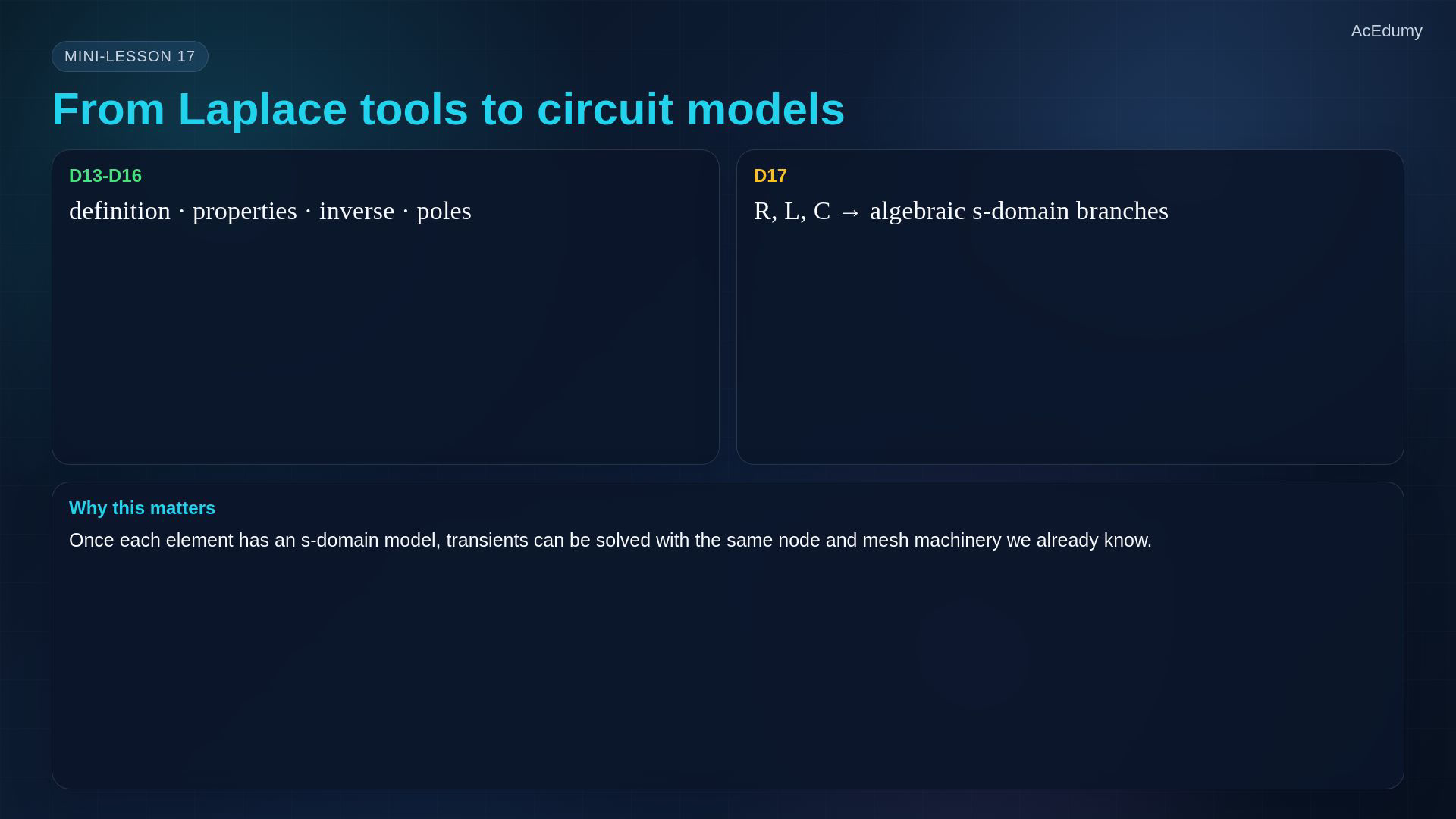
Original-video reference. Two unsuitable source cards use other cards from this same final; complete equations, signs and qualifications are written in the notebook lines. Laplace tools: definition, shifting, inversion, poles, zeros and endpoint checks.Now connect those tools to ideal linear circuit elements.Replace each constant-parameter time-domain law with a unilateral s-domain equation.The ideal resistor remains memoryless:Inductor current and capacitor voltage at zero minus become initial-state source terms.Next, use these branch models in node and mesh equations.Narration transcript
We have built the Laplace toolkit: definition, shifting rules, inverse Laplace, poles, zeros, and endpoint checks. Now we connect that toolkit back to real circuits. The goal is simple: take each time-domain element and replace it with an algebraic model in the s-domain. Resistors will look almost unchanged. Inductors and capacitors will carry memory, so their initial current or initial voltage becomes a source term. Once we can do this, the next lesson can write node and mesh equations directly in s.
2. Keep the stored state at zero minus
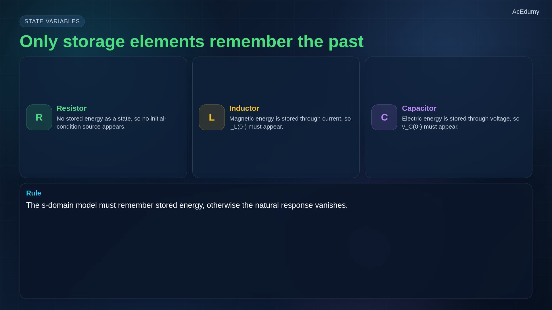
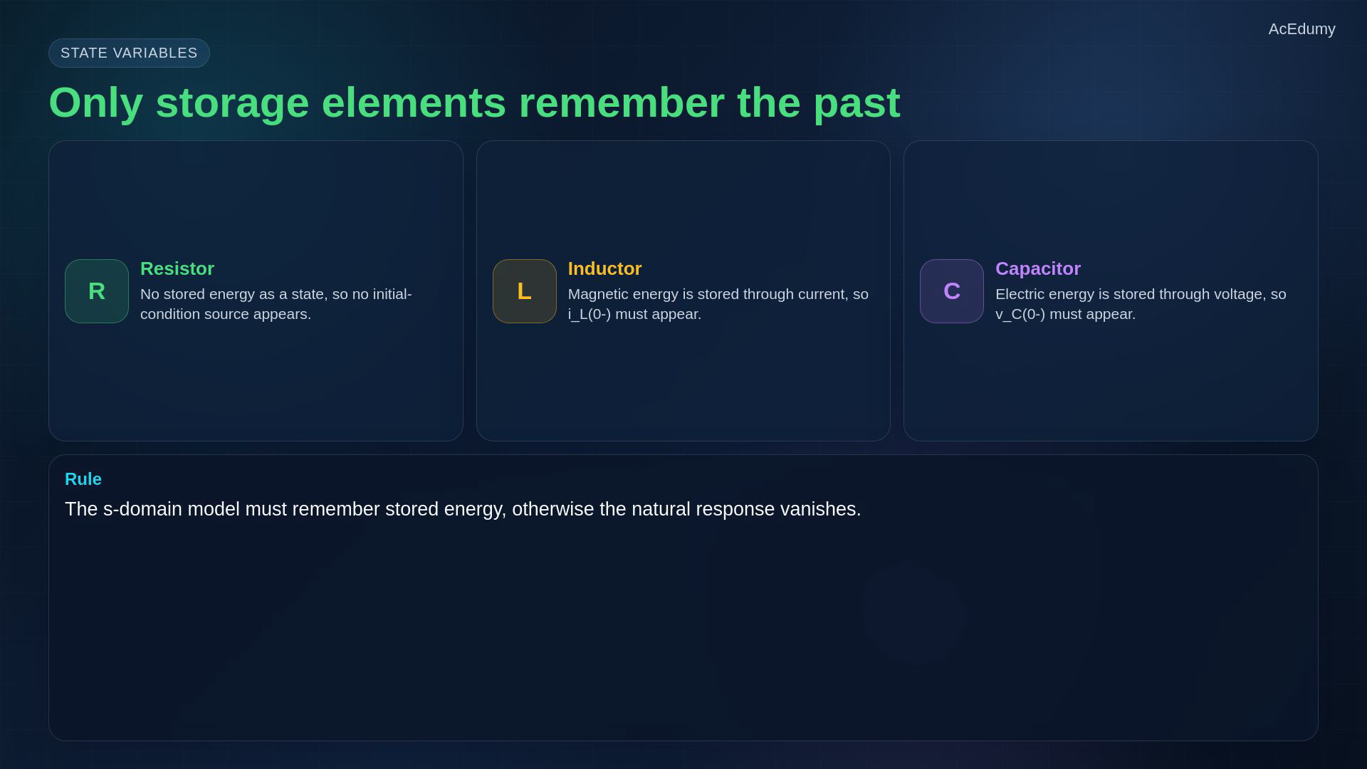
Original-video reference. Two unsuitable source cards use other cards from this same final; complete equations, signs and qualifications are written in the notebook lines. Ideal R, L and C differ in whether they store a state.The ideal resistor has no stored state and no initial-condition source.Magnetic energy depends on the inductor current immediately before switching:Electric energy depends on the capacitor voltage immediately before switching:Zero minus means just before switching; equality to zero plus requires the relevant state to be continuous.Omitting stored-state terms loses the zero-input natural response; a driven zero-state response can still contain transients.Narration transcript
The dividing line is energy storage. A resistor does not store energy as a state, so it has no initial-condition term. An inductor stores magnetic energy, and the state variable is its current, i L of zero minus. A capacitor stores electric energy, and the state variable is its voltage, v C of zero minus. The zero minus notation matters: it is the value just before switching. The s-domain model must remember this stored energy, otherwise the transient part of the answer disappears.
3. Transform the memoryless resistor
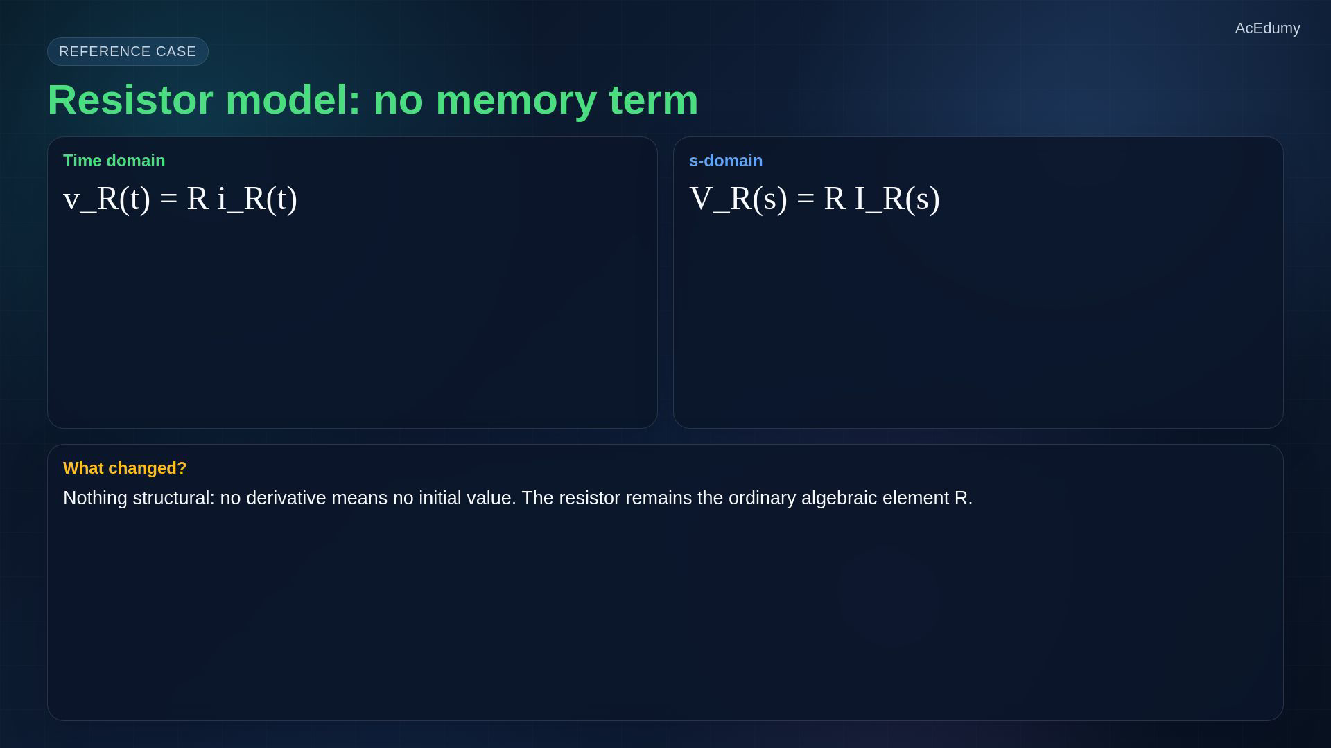
Original-video reference. Two unsuitable source cards use other cards from this same final; complete equations, signs and qualifications are written in the notebook lines. Start with the ideal constant resistor and the passive sign convention.Current enters the positive terminal:Take the unilateral transform of the complete law:No derivative means no separate initial-condition term in this element law.Its impedance has resistance units:Storage elements add initial-state terms; a resistor itself does not.Narration transcript
Start with the resistor, because it is the clean reference case. In the time domain, v R of t equals R times i R of t. The Laplace transform is direct: V R of s equals R times I R of s. No derivative appears, so no initial condition appears. In the s-domain circuit, the resistor is still just R. This is why resistive parts of the network become ordinary algebra, while storage elements bring the extra memory terms.
4. Derive the inductor source sign
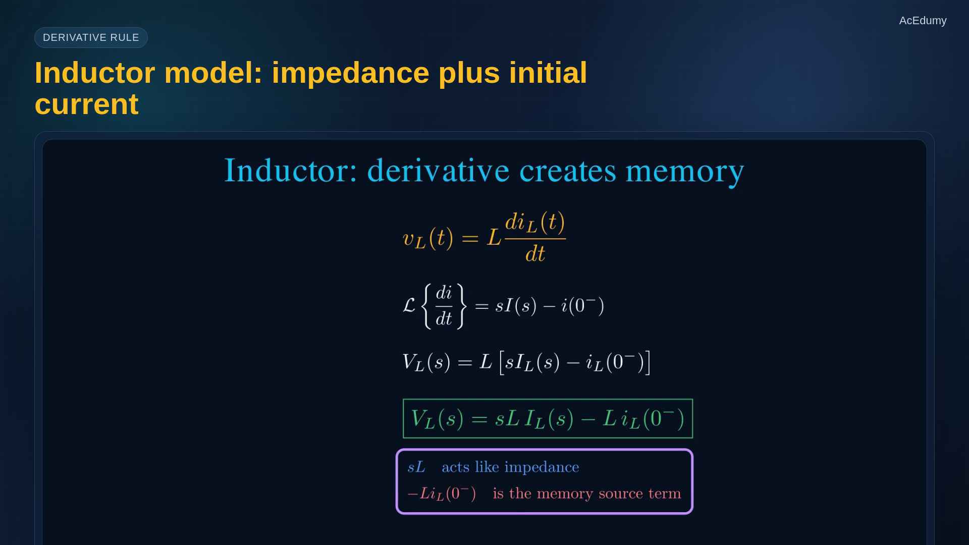
Original-video reference. Two unsuitable source cards use other cards from this same final; complete equations, signs and qualifications are written in the notebook lines. Passive convention: the referenced inductor current enters its positive voltage terminal.For constant inductance:The derivative subtracts the zero-minus value inside the brackets:Distribute L to both terms:Impedance and signed series-voltage source are different quantities:The transformed source has volt-second units, not ohms; do not add impedance directly to initial current.Narration transcript
For an inductor, use the passive sign convention: current enters the positive voltage terminal. The time-domain law is v L equals L d i L over d t. The Laplace derivative rule gives V L of s equals L times s I L of s minus i L of zero minus. So V L of s equals s L I L of s minus L i L of zero minus. Read this as an impedance s L, plus a series source term caused by the initial current. The inductor is not only an impedance; it also remembers its current before switching.
5. Derive the capacitor source sign
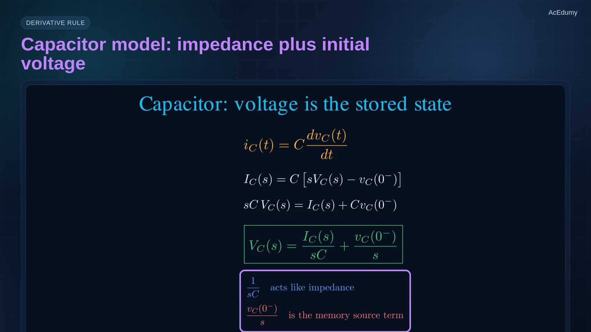
Original-video reference. Two unsuitable source cards use other cards from this same final; complete equations, signs and qualifications are written in the notebook lines. The capacitor stores voltage; use the same passive convention.For constant capacitance:Keep the initial voltage inside the derivative brackets:Solve for voltage with two separate fractions:Impedance and signed series-voltage source:The source is a transformed voltage with volt-second units; the stored state is voltage, not current.Narration transcript
For a capacitor, the stored variable is voltage. With passive sign convention, i C equals C d v C over d t. Taking the Laplace transform gives I C of s equals C times s V C of s minus v C of zero minus. If we solve this for voltage, V C of s equals I C of s over s C, plus v C of zero minus over s. So the impedance is one over s C, and the initial voltage appears as a series voltage source. The capacitor remembers voltage exactly the way the inductor remembers current.
6. Keep impedance and source terms distinct
Original-video reference. Two unsuitable source cards use other cards from this same final; complete equations, signs and qualifications are written in the notebook lines. Compare complete branch equations, not sums of unlike units.Resistor:Inductor, using current into the positive voltage terminal:Capacitor, with the same convention:Source signs follow the derivative rule and the chosen references.If a reference reverses, transform every affected variable and initial value consistently.Choose references, write the physical law, transform it, then draw the source polarity.Narration transcript
Put the three models side by side. The resistor is R. The inductor is s L with an initial-current source term, L i zero minus. The capacitor is one over s C with an initial-voltage source term, v zero minus over s. The signs are not arbitrary; they come from the derivative rule and the chosen reference directions. If a branch current or voltage reference is reversed, the algebra changes sign with it. The safe method is always to write the element law first, then transform it.
7. Solve the RC natural response
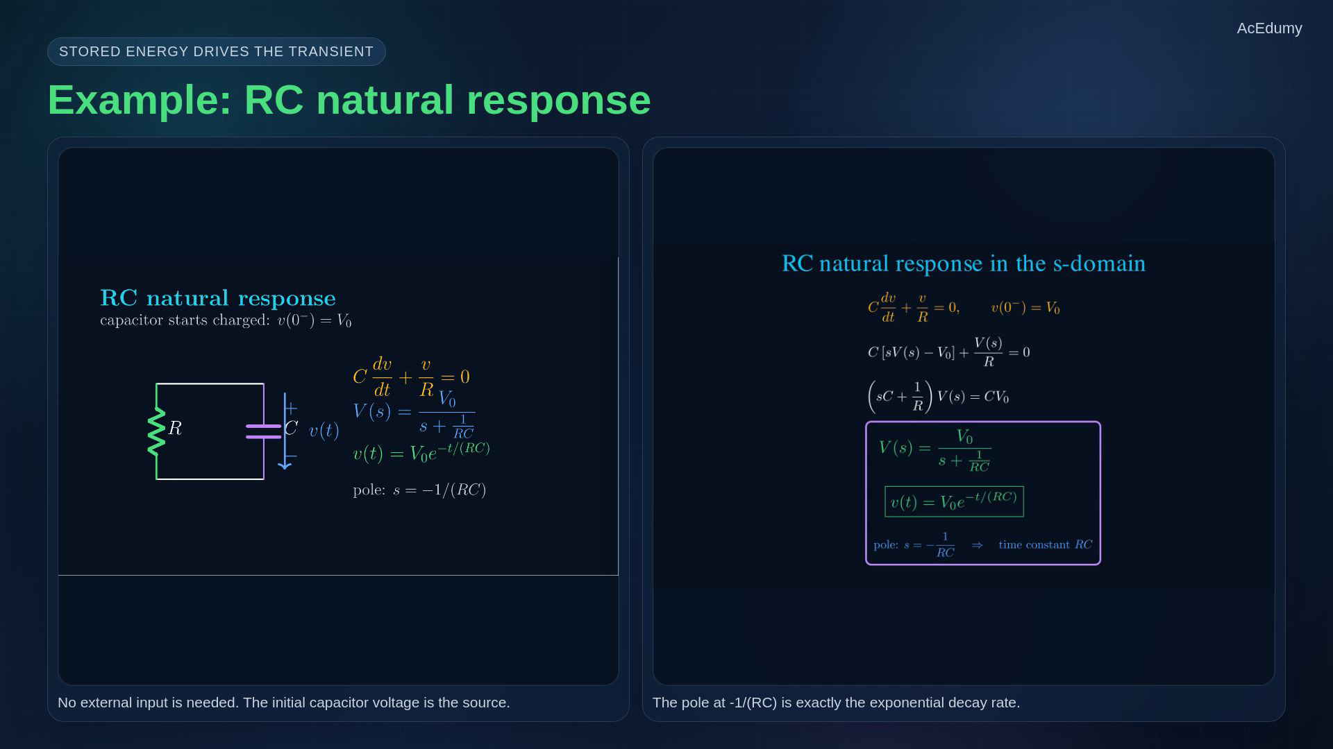
Original-video reference. Two unsuitable source cards use other cards from this same final; complete equations, signs and qualifications are written in the notebook lines. Example: an initially charged capacitor discharging through a resistor, with no external input.Assume positive R and C, and no switching impulse in capacitor current:Take both branch currents from the top node toward the bottom; for positive time:With the zero-minus unilateral convention:Collect V and divide by C; the whole denominator matters:For positive time, with positive decay rate a:For nonzero V_0 the transform pole is negative; the time constant is its reciprocal magnitude:Narration transcript
Now a tiny example. A capacitor starts with voltage V naught, and then discharges through a resistor R. The current through the capacitor plus the resistor current must sum to zero, so C d v over d t plus v over R equals zero. Taking Laplace gives C times s V of s minus V naught, plus V of s over R equals zero. Collect V of s, and we get V of s equals V naught over s plus one over R C. In time domain, this is V naught e to the minus t over R C. The pole is at minus one over R C.
8. Check switching values and source polarities
Original-video reference. Two unsuitable source cards use other cards from this same final; complete equations, signs and qualifications are written in the notebook lines. Four checks: switching value, memoryless resistor, source polarity and zero-input response.Use zero minus in this unilateral convention; do not assume continuity across an impulsive switching event.Do not invent an initial source for an ideal resistor.Derive polarity from the element law and chosen references.Zero external input does not mean zero initial energy.Stored energy drives the zero-input natural response; external inputs can also generate transient terms.Narration transcript
There are four common traps. First, use zero minus, not zero plus, for the stored initial value before the switching event. Second, do not invent an initial source for a resistor. Third, do not memorize the source polarity blindly; derive the sign from the reference directions. Fourth, do not drop the initial term just because there is no external input. A natural response is driven exactly by stored energy.
9. Carry the initial state into node and mesh equations
Original-video reference. Two unsuitable source cards use other cards from this same final; complete equations, signs and qualifications are written in the notebook lines. Summary: use complete branch equations with their initial-state sources.Resistor:Inductor:Capacitor:Initial states supply transformed source terms; impedance alone is not the full model.Next: s-domain node and mesh equations, followed by inversion and time-domain checks.Narration transcript
Summary. A resistor stays R in the s-domain. An inductor becomes s L and remembers its initial current. A capacitor becomes one over s C and remembers its initial voltage. These source terms are the bridge between physical stored energy and algebraic circuit equations. Next, we will use these models to write node and mesh equations directly in the s-domain, then solve the transient response as algebra.
Source video: Circuit Theory-2 #17 | s-Domain RLC Models with Initial Conditions (5:46)