Electronics 1 · Electronics Basics
#06 Series biased clippers — transition voltage and four variations
Use transition voltage, diode orientation, and battery direction to solve all four ideal series-biased clipper variations.
Question
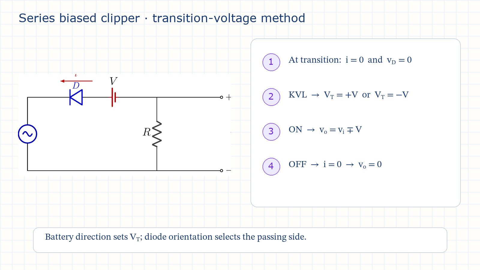
For the four ideal series-biased clipper circuits, take V_m = 10 V and the DC bias magnitude V = 3 V. Determine the transition voltage, the ON/OFF region, and the piecewise output v_o for variations 3 through 6. Explain how battery direction sets the transition level, how diode orientation selects the passing side, and how a 0.7 V silicon drop shifts the ideal transition.
Written solution and narration transcript(shows the full solution)
Below are all the lines written in the notebook together with the full narration transcript.
1. Why add a bias source?
The battery moves the transition away from zero while the diode remains the automatic switch. Simple series clipper: transition at 0 VAdd a DC source V in series with DBias moves the clipping level away from zeroDirection 1 → VT = +V; Direction 2 → VT = −VDiode orientation: positive or negative2 battery directions × 2 diode orientations = 4 variationsNarration transcript
Welcome back. In the last lesson we built series simple clippers. One diode in series with the load resistor, and the clipping level was always exactly zero volts. The diode switched state right at the zero crossing of the input. Today we keep the same series path, but we add one new component: a DC battery, in series with the diode. This battery is called a bias source. Its only job is to move the clipping level away from zero. With the right battery, the diode can switch on at plus three volts, or at minus three volts, instead of at zero. The input voltage where the diode changes state is called the transition voltage. In a simple clipper the transition voltage is zero. In a biased clipper, the battery sets it. We will look at four variations. Two choices: the diode orientation, positive or negative, and the battery direction, one or two. Two times two gives four biased series clippers.
2. Transition-voltage method
The two switching conditions turn the circuit into a repeatable piecewise-analysis problem. At the switching instant:i = 0 and vD = 0Apply KVL around the series loopVT = vi(switch) = +V or −VD ON → vo = vi ∓ VD OFF → i = 0 → vo = 0Find VT first; then write vo on each sideNarration transcript
Before the circuits, here is the method, and it is the same every time. The diode is still an automatic switch. When it is forward biased it is on and acts like a short circuit. When it is reverse biased it is off and the branch is open. The key question is: at which input voltage does it switch? At that exact switching instant, two things are true together. The current i is zero, because the diode is just leaving the off state. And the diode voltage v D is zero, because it is just entering the on state. Apply Kirchhoff's voltage law around the loop with both conditions, and you get one input value. That value is the transition voltage. For a series biased clipper the loop gives v i equals plus or minus V. Once you know the transition voltage, the rest is easy. On one side of it the diode is on, and the output follows v i shifted by the battery. On the other side the diode is off, current is zero, and v o equals i times R equals zero. So: find the transition voltage first, then write v o on each side.
3. Variation 3 — wide region below
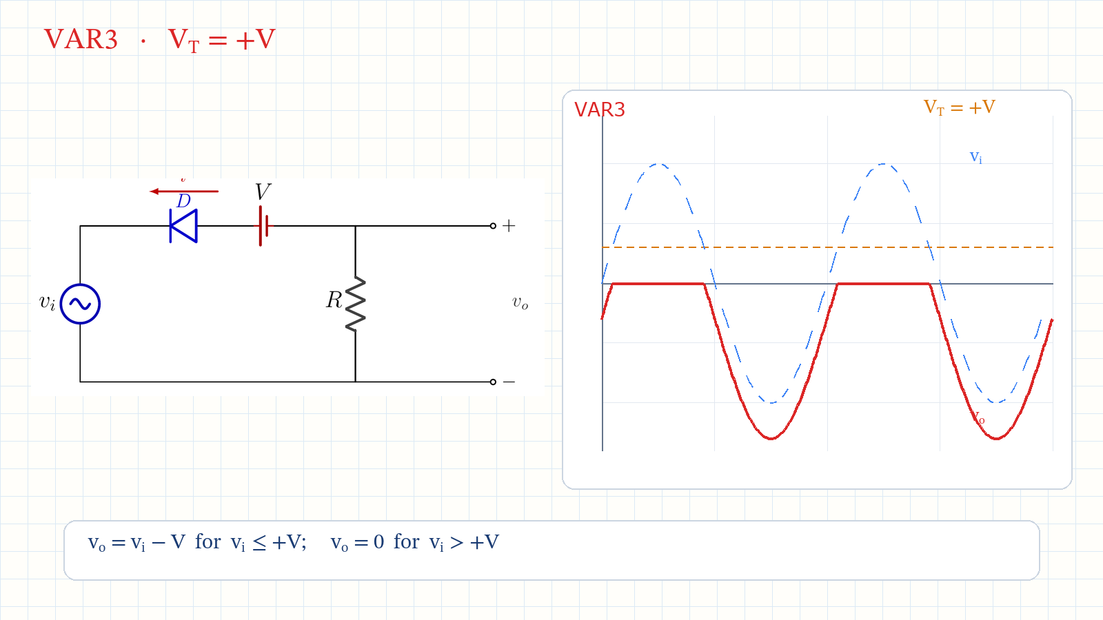
Positive orientation passes the region below +V; direction 1 produces v_o = v_i − V while ON. Variation 3: positive · direction 1D ON for vi ≤ +3 Vvo = vi − 3 V for vi ≤ +3 Vvo = 0 for vi > +3 VOutput range:Wide shifted wave; only the positive tip is clippedNarration transcript
Variation three: positive, series, biased, direction one. Take the positive series clipper from last lesson and add the battery in direction one. Direction one places the transition voltage at plus V. Kirchhoff's voltage law around the loop while the diode conducts gives v o equals v i minus V. Set v o to zero, and the transition voltage is v i equals plus V, plus three volts. A positive clipper passes the region below the transition line. So the diode is on for almost the whole cycle, whenever v i is below plus three volts, and there v o equals v i minus three. Only the very tip of the positive peak, above plus three volts, finds the diode off, and that tip is clipped to zero. The output looks like the input shifted down by three volts, with the top of the positive peak flattened. The bias did not block a half cycle; it sliced off one peak tip and shifted the rest.
4. Variation 4 — positive tip
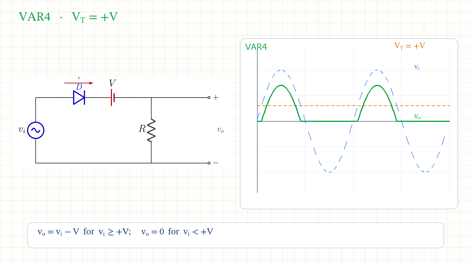
Flipping only the diode keeps the same +V transition but selects the narrow region above it. Variation 4: negative · direction 1D ON for vi ≥ +3 Vvo = vi − 3 V for vi ≥ +3 Vvo = 0 for vi < +3 VOutput range:Only a narrow positive peak survivesNarration transcript
Variation four: negative, series, biased, direction one. Same battery, same direction one, so the transition voltage is still plus three volts. But now the diode is in the negative orientation. Kirchhoff's voltage law in the on state again gives v o equals v i minus V. A negative clipper passes the region above the transition line. So the diode is on only when v i is above plus three volts. There v o equals v i minus three. Everywhere below plus three volts the diode is off, current is zero, and v o is zero. The output is just a small positive bump, the tip of the positive peak, rising from zero up to seven volts. Compare it with variation three. Same transition line at plus three, only the diode flipped. Variation three kept the wide region below the line; variation four keeps only the narrow tip above it. The diode orientation decides which side of the transition survives.
5. Variation 5 — negative tip
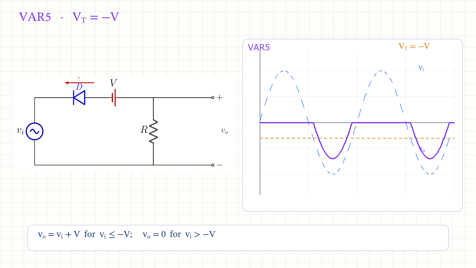
Direction 2 moves the transition to −V; the positive orientation keeps the narrow region below it. Variation 5: positive · direction 2D ON for vi ≤ −3 Vvo = vi + 3 V for vi ≤ −3 Vvo = 0 for vi > −3 VOutput range:Only a narrow negative peak survivesNarration transcript
Variation five: positive, series, biased, direction two. Now reverse the battery into direction two. Direction two moves the transition voltage to minus V. Kirchhoff's voltage law in the on state gives v o equals v i plus V. Setting v o to zero, the transition voltage is v i equals minus V, minus three volts. This is a positive clipper, so it passes the region below the transition line. The line is now down at minus three volts, so the diode is on only when v i is below minus three volts. There v o equals v i plus three. The output is a small negative bump, just the tip of the negative peak, reaching down to minus seven volts. So a positive clipper with direction two keeps only a narrow negative tip, the mirror of variation four.
6. Variation 6 — wide region above
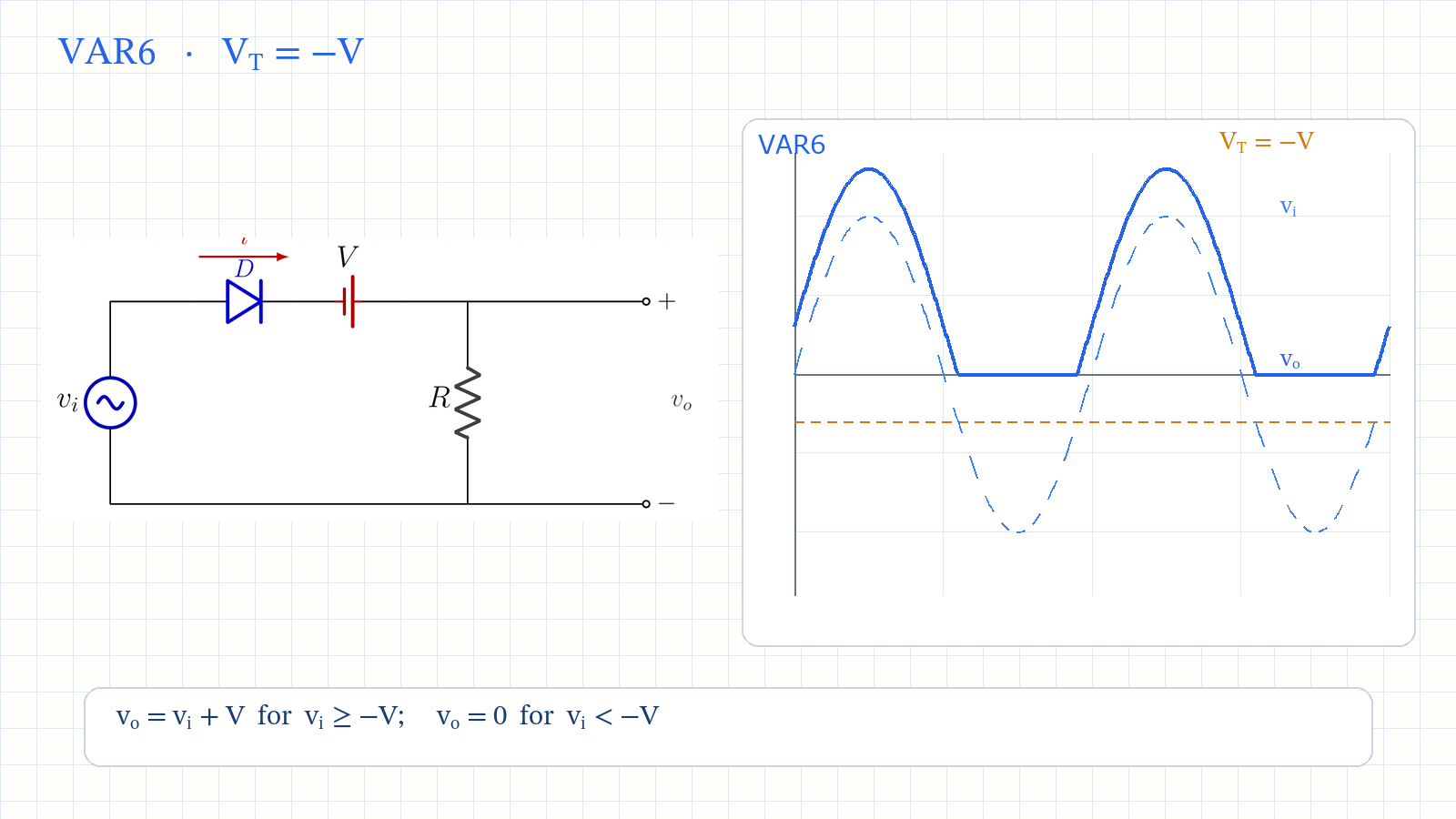
Negative orientation passes the wide region above −V; only the bottom tip is removed. Variation 6: negative · direction 2D ON for vi ≥ −3 Vvo = vi + 3 V for vi ≥ −3 Vvo = 0 for vi < −3 VOutput range:Wide shifted wave; only the negative tip is clippedNarration transcript
Variation six: negative, series, biased, direction two. Battery in direction two, so the transition voltage is minus three volts, and the diode is in the negative orientation. Kirchhoff's voltage law in the on state gives v o equals v i plus V. A negative clipper passes the region above the transition line. The line sits at minus three volts, so the diode is on for almost the whole cycle, whenever v i is above minus three volts. There v o equals v i plus three, the input shifted up by three volts. Only the bottom tip of the negative peak, below minus three volts, is clipped to zero. Variation six is the mirror of variation three: a wide conduction window, the wave passing shifted, and just one peak tip removed, but this time shifted up instead of down.
7. Four-case map and silicon shift
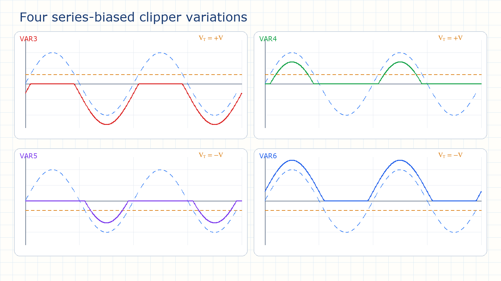
Battery direction fixes the transition line; diode orientation chooses the side that survives. Battery direction sets the transition:Direction 1 → +V; Direction 2 → −VPositive clipper passes below VTNegative clipper passes above VTWide windows: variations 3 and 6Narrow tips: variations 4 and 5Silicon: include VF ≈ 0.7 V in the switching KVLFor V = 3 V, transitions become about 2.3 V or 3.7 VNarration transcript
Let us put all four together. Every series biased clipper is one diode, one resistor, and one DC battery in the loop. The battery sets the transition voltage. Direction one puts the transition line at plus V, above zero. Direction two puts it at minus V, below zero. Then the diode orientation decides which side of that line passes. A positive clipper passes the region below the line. A negative clipper passes the region above it. That gives the four outcomes. Variations three and six keep a wide region: the wave passes, shifted by V, with one peak tip clipped. Variations four and five keep only a narrow tip: a small bump at one peak. The method never changed. Find the transition voltage from i equals zero and v D equals zero, then write v o on each side. One practical note. We used the ideal diode, so the transition voltage is exactly plus or minus V. A real silicon diode adds its forward drop of about zero point seven volts. For example, with a three volt battery the transition shifts to about two point three or three point seven volts, depending on the diode orientation. Next lesson we move the diode from in series with the load to in parallel with it: the parallel clipper. See you there.
Source video: Electronics Basics #06 | Series Biased Clippers: Transition Voltage and the Four Variations (8:14)