Electronics 1 · Electronics Basics
#05 Series simple clippers — positive and negative
Use the ideal-diode switch method to determine which half-cycle passes and which is clipped in positive and negative series clippers.
Question
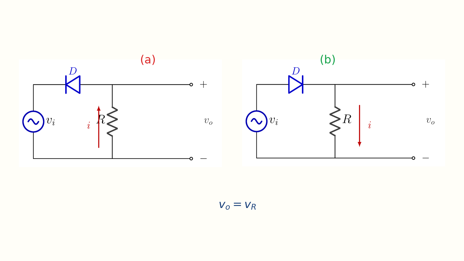
For the two ideal series clipper circuits, determine the diode state, current, and output voltage during the positive and negative input half-cycles. Explain why the positive clipper removes the positive half-cycle while the negative clipper removes the negative half-cycle, and state how a real silicon diode changes the ideal transition.
Written solution and narration transcript(shows the full solution)
Below are all the lines written in the notebook together with the full narration transcript.
1. Clipper analysis method
Circuit (a) clips the positive half-cycle; reversing the diode in circuit (b) clips the negative half-cycle. A clipper removes part of a waveform.The diode acts as an automatic switch: forward bias → ON; reverse bias → OFF.Series clipper: D is in the load-current path.1) Choose the half-cycle: vi > 0 or vi < 0.2) Decide whether D is ON or OFF.3) Ideal D: ON → short circuit; OFF → open circuit.Then find vo across R and compare both diode orientations.Narration transcript
Welcome back. We have finished the basic rectifier idea. Now we start a new diode application: clipping. A clipper circuit removes, or clips, part of a waveform. The diode is used like an automatic switch. When it is forward biased, it turns on and lets current flow. When it is reverse biased, it turns off and the branch becomes open. In this lesson we use the simplest version: the series clipper. Series means the diode is in series with the load resistor. Our analysis method is always the same. First, choose the input half cycle. Is v i positive or negative? Second, decide whether the diode is on or off. Third, replace the ideal diode with a short circuit when it is on, or an open circuit when it is off. Then compute the output voltage v o across the resistor. Today we will compare two orientations: the positive series clipper and the negative series clipper.
2. Positive series clipper
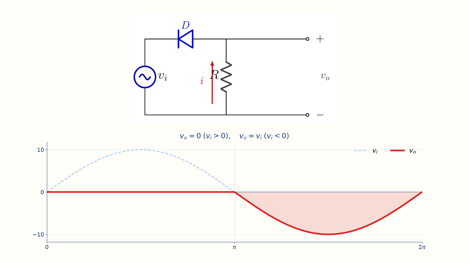
The positive half-cycle is clipped to zero; the negative half-cycle follows the input. Positive series clipperNaming rule: it clips the positive half-cycle.vi > 0 → D OFF → series path openi = 0 → vo = iR = 0 Vvi < 0 → D ON (ideal short) → vo = viNegative half passes; positive half is clipped.Narration transcript
Here is variation one: the positive series simple clipper. The name can feel backwards at first, so keep the rule in mind: a positive clipper clips the positive half cycle. Look at the diode direction. When the input v i is positive, the diode is reverse biased. It is off, so the series path is open. That means the current is zero. If i equals zero, then the resistor voltage is v o equals i times R, which is zero volts. So the positive half cycle does not appear at the output. Now flip the input. When v i is negative, the diode is forward biased. It turns on and behaves like a short circuit. The load is now connected to the source, so the output follows the negative input. For an ideal diode, v o equals v i during the negative half cycle. So this circuit passes the negative half and clips the positive half to zero.
3. Positive-clipper waveform
The positive half-cycle is clipped to zero; the negative half-cycle follows the input. Dashed: input vi · solid: output vovi > 0 → D OFF → vo = 0vi < 0 → D ON → vo = viIdeal rule: vo = 0 for vi > 0Ideal rule: vo = vi for vi < 0The ideal model switches instantly at vi = 0.A silicon diode shifts the transition by about 0.7 V.Simple ideal clipper level: 0 VNarration transcript
The waveform makes the result obvious. The dashed sine wave is the input. For the positive portions of the sine, the diode is off, so the output is forced to zero. For the negative portions, the diode is on, so the output copies the input. Written as a simple ideal rule: when v i is greater than zero, v o equals zero. When v i is less than zero, v o equals v i. At the zero crossings the ideal model changes state instantly. In a real silicon diode the transition is not perfectly sharp, and the forward drop is about zero point seven volts. But for the ideal clipper model, the clipping level is exactly zero volts. That is why this first pair is called simple clippers.
4. Negative series clipper
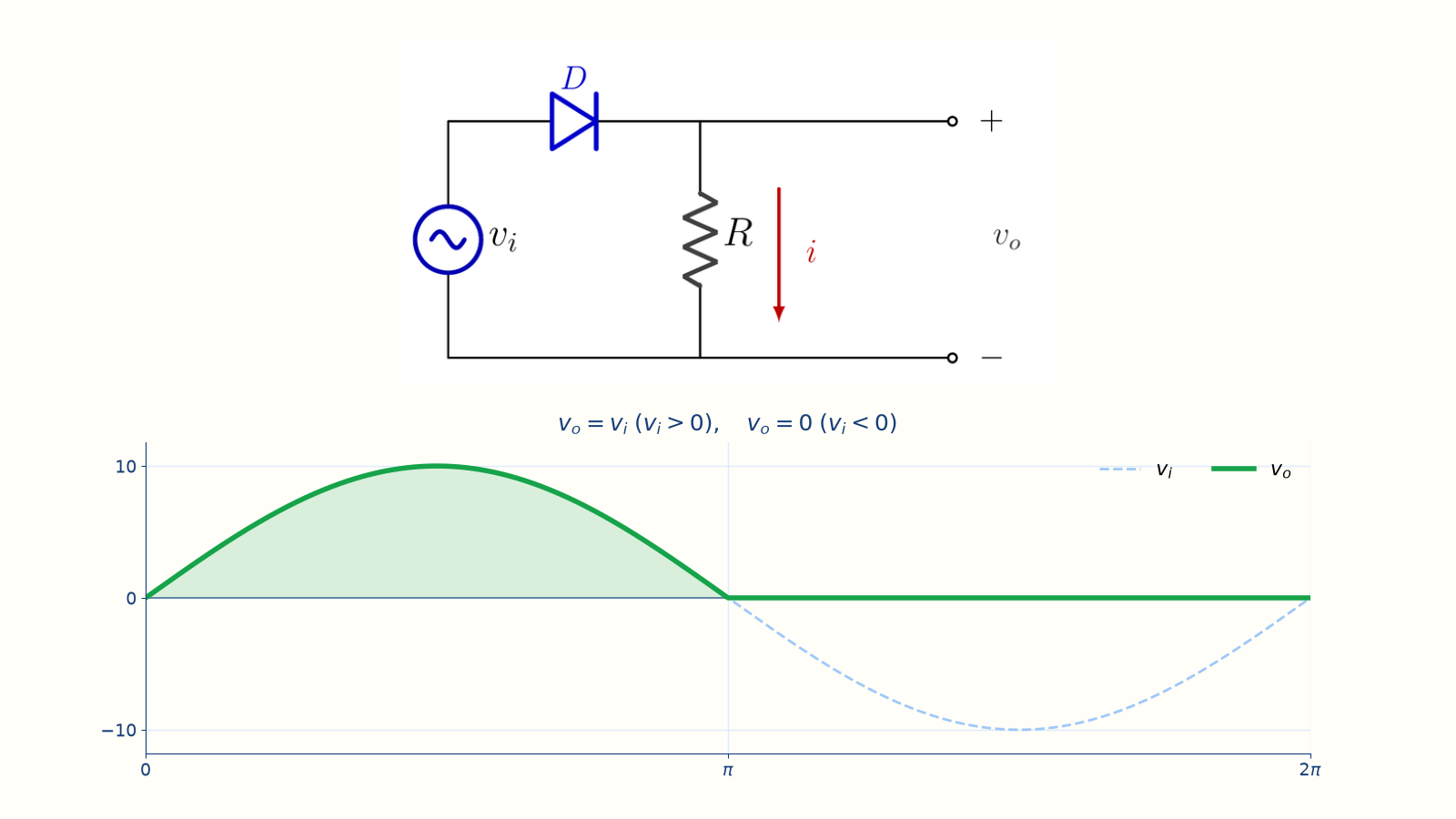
The negative half-cycle is clipped to zero; the positive half-cycle follows the input. Reverse the diode orientation.vi > 0 → D ON → vo = vivi < 0 → D OFF → i = 0 → vo = 0The negative half-cycle is removed.Positive half passes; negative half is clipped.Narration transcript
Now reverse the diode. This gives variation two: the negative series simple clipper. The circuit is almost the same, but the diode orientation is flipped. When v i is positive, the diode is forward biased. It turns on, the source is connected to the resistor, and the output follows the positive input. So for v i greater than zero, v o equals v i. When v i becomes negative, the diode becomes reverse biased. It turns off and opens the series path. The current becomes zero, and therefore v o equals i times R equals zero volts. So the negative half cycle is removed. That is the naming rule again: a negative clipper clips the negative half cycle. It passes the positive half and forces the negative half to zero.
5. Compare the two circuits
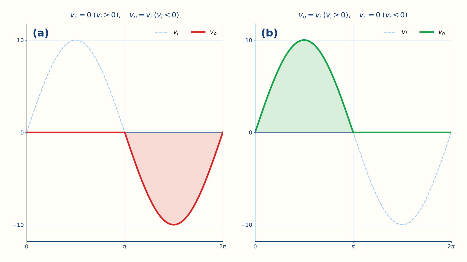
One diode orientation selects which input half-cycle reaches the load. Same circuit, opposite diode directionPositive clipper: blocks + half, passes − half.Negative clipper: blocks − half, passes + half.D, R, and the output measurement are otherwise unchanged.Do not memorize the drawing; find the forward-biased half-cycle.Forward-biased half-cycle → series path conducts.Other half-cycle → D OFF → i = 0 → vo = 0 V.Narration transcript
Put the two circuits side by side and the pattern is simple. In a positive series clipper, the positive half is blocked and the negative half passes. In a negative series clipper, the negative half is blocked and the positive half passes. The only difference is the diode orientation. Everything else is the same: one diode, one resistor, and the output measured across the resistor. This is also a useful way to analyze any diode waveform circuit. Do not memorize every drawing. Instead, ask which half cycle makes the diode forward biased. That half cycle can pass through the series path. The other half cycle leaves the diode off, current equal to zero, and the resistor output equal to zero. For simple ideal series clippers, the clipping level is zero volts.
6. Method summary
One diode orientation selects which input half-cycle reaches the load. Series simple clippersD is in series with the load resistor.D ON → load sees the source → selected half-cycle passes.D OFF → open path → i = 0 → vo = 0.Positive clipper: clips +, passes −.Negative clipper: clips −, passes +.Simple ideal clipping level: 0 VNext: add a DC source to move the clipping level.Narration transcript
Let us recap. A clipper removes part of a waveform. A series clipper puts the diode in series with the load resistor. If the diode is on, the load sees the source and the selected half cycle passes. If the diode is off, the path is open, current is zero, and the output across the resistor is zero. The positive series clipper clips the positive half and passes the negative half. The negative series clipper clips the negative half and passes the positive half. These are simple clippers because the clipping level is zero volts. Next, we will add a DC source in series with the diode. That biased clipper lets us move the clipping level above or below zero. See you in the next lesson.
Source video: Electronics Basics #05 | Series Clipper Circuits: Positive and Negative Simple Clippers (5:39)