Circuit Theory 2 · Sinusoidal signals and phasors
#01 Sinusoidal steady state, rotating-vector projections, amplitude, angular frequency, phase, and the phasor shortcut
Connect a sinusoid to a rotating vector and keep its magnitude and phase, with clear projection, frequency and amplitude conventions.
Question
Explain the bridge from switching transients to sinusoidal steady state. For a counterclockwise rotating vector, distinguish the horizontal cosine projection from the vertical sine projection; they are not the same waveform at the same angle. Define peak amplitude V_m, angular frequency ω in rad/s, frequency f in Hz, period T in seconds, and phase φ in radians measured from the positive horizontal axis. Use a positive frequency and the peak-magnitude, cosine-reference phasor convention. Explain why a phasor is time-independent when the common rotation is factored out; its frequency must still be specified. Define t_0 as the time shift in cos(ω(t−t_0)). The RMS relation shown applies to a pure zero-mean sinusoid; do not mix peak and RMS phasors. Phase is undefined when amplitude is zero. The retained frame is a source reference, not a newly generated synchronized animation.
Written solution and narration transcript(shows the full solution)
Below are all the lines written in the notebook together with the full narration transcript.
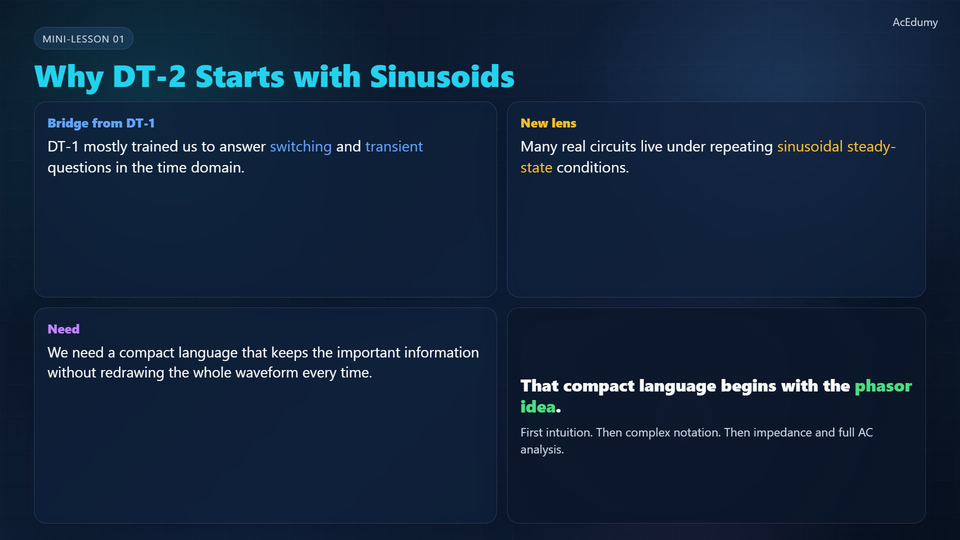
1. Move from switching to sinusoidal steady state
Source reference: cosine and sine use different projection axes. The phasor shortcut keeps magnitude and phase at a stated frequency; the diagrams are conceptual, not matching numerical time samples. DT-1 emphasized switching and transient responses in the time domain.Now consider a sinusoidal source after the circuit's transient response has died away.Alternating-current (AC) steady-state analysis treats one fixed frequency at a time.Narration transcript
In D T 1, we mostly asked time-domain switching questions. But many real circuits operate with repeating sinusoidal sources in steady state. Circuit Theory 2 begins when we change from switch thinking to steady-state A C thinking.
2. Read a rotating vector's projection
Source reference: cosine and sine use different projection axes. The phasor shortcut keeps magnitude and phase at a stated frequency; the diagrams are conceptual, not matching numerical time samples. Picture a vector rotating counterclockwise at constant angular speed.For an angle measured from the positive horizontal axis, the horizontal projection is:The vertical projection is a different, phase-shifted sinusoid for that same angle:Narration transcript
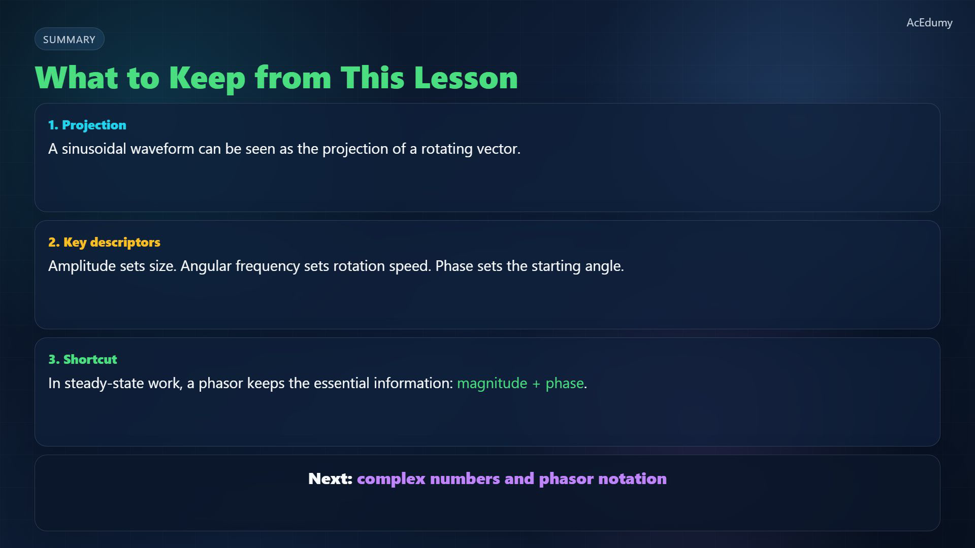
Here is the key picture. A sinusoidal waveform can be viewed as the projection of a rotating vector. As the vector turns, its shadow on an axis creates the familiar sinusoid.
3. Separate amplitude, angular frequency and phase
Source reference: cosine and sine use different projection axes. The phasor shortcut keeps magnitude and phase at a stated frequency; the diagrams are conceptual, not matching numerical time samples. Choose a peak amplitude, a positive angular frequency, and an initial phase.Peak amplitude is vector length; for a pure zero-mean sinusoid the root-mean-square (RMS) value is:Angular frequency ω is in rad/s, while f is in cycles/s (Hz):The initial phase is the angle at t=0; a positive φ advances the cosine in time:Narration transcript
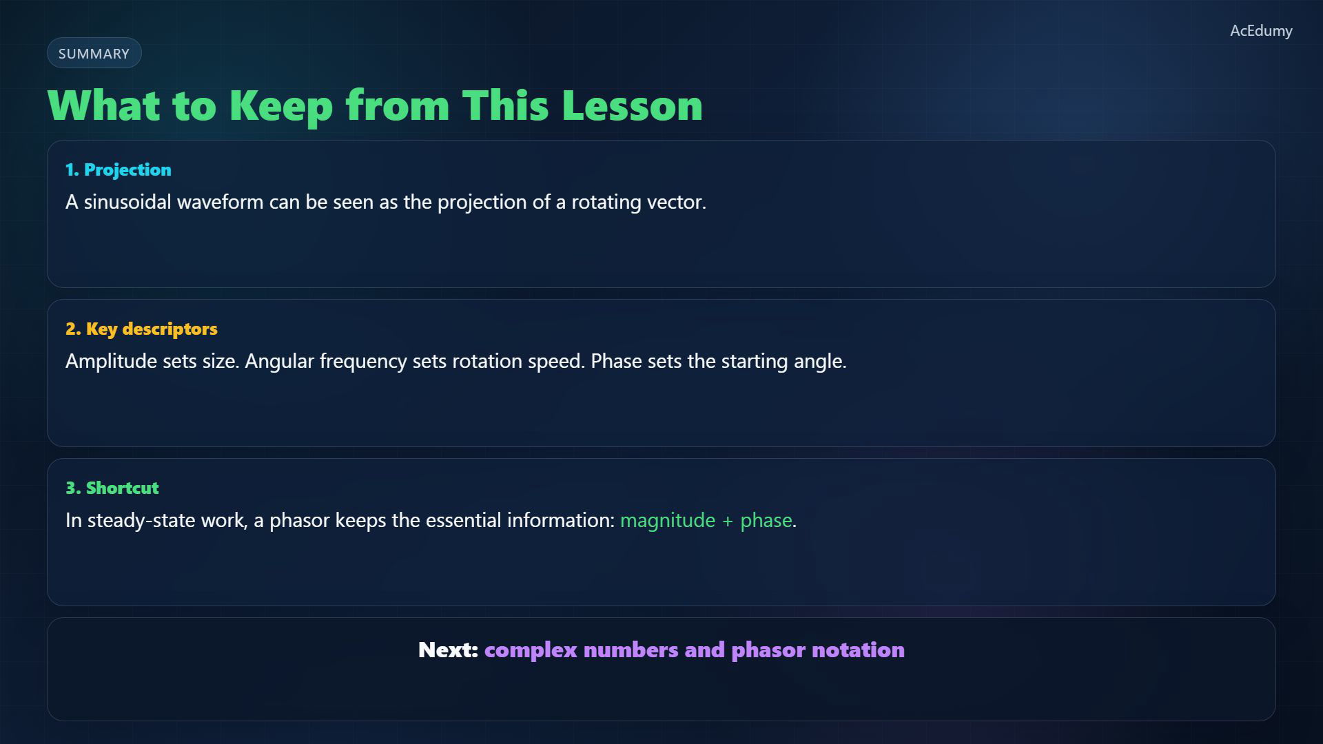
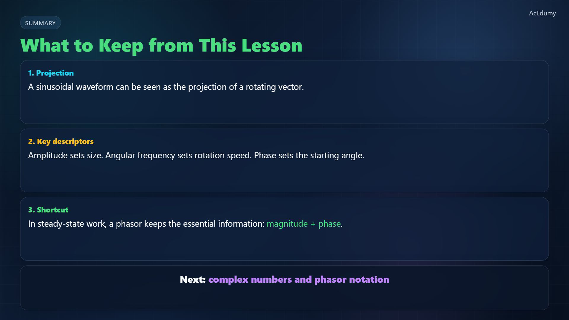
Three quantities control that motion. The amplitude sets the vector length. Omega sets how fast it rotates. And phi sets the starting angle, or phase.
4. Keep magnitude and phase in a phasor
Source reference: cosine and sine use different projection axes. The phasor shortcut keeps magnitude and phase at a stated frequency; the diagrams are conceptual, not matching numerical time samples. At the chosen frequency, factor out the shared rotation; the phasor itself is time-independent.Using peak magnitude and a cosine reference, write the phasor as:Narration transcript
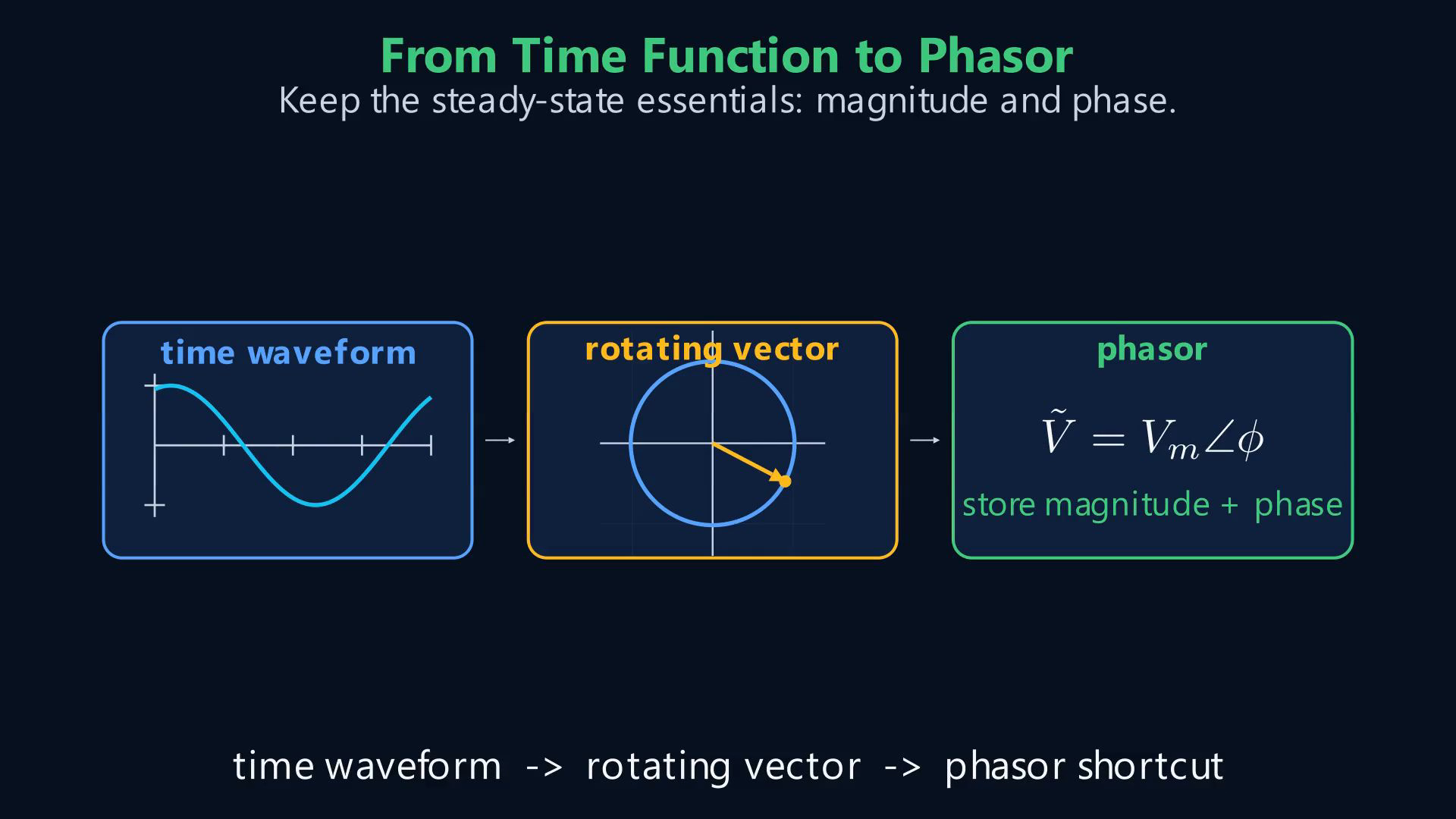
Instead of redrawing the whole time waveform at every instant, we can keep the essential steady-state information in a phasor. A phasor stores magnitude and phase in one compact object.
5. Connect the waveform to complex notation
Source reference: cosine and sine use different projection axes. The phasor shortcut keeps magnitude and phase at a stated frequency; the diagrams are conceptual, not matching numerical time samples. The waveform changes with time; the phasor records its magnitude and initial phase at a stated frequency.Next: represent the same phasor in complex polar and rectangular notation, keeping the amplitude convention fixed.Narration transcript
So the bridge is this: time waveform, rotating vector, then phasor. In the next lesson, we will write phasors with complex numbers and use them as the language of A C analysis.
Source video: Circuit Theory-2 #01 Sinusoidal Signals and the Phasor Idea (1:16)