Control Theory · Sinusoidal Steady-State and Frequency Response — Lecture 5, Part 1
#44 G(jω), sinusoidal steady-state magnitude and phase for stable LTI systems, quadrant-safe atan2 phase, and the decibel scale
Connect s=jω, magnitude, phase, decibels, and the first-order low-pass example in one assumption-safe calculation chain.
Question
Derive the steady-state response of a stable LTI system to a unit-amplitude sinusoid using G(jω). Compute the magnitude, phase, and decibel behavior of G(s)=1/(s+1), and state the quadrant-safe atan2 rule and validity assumptions.
Written solution and narration transcript(shows the full solution)
Below are all the lines written in the notebook together with the full narration transcript.
1. Move from time response to frequency response
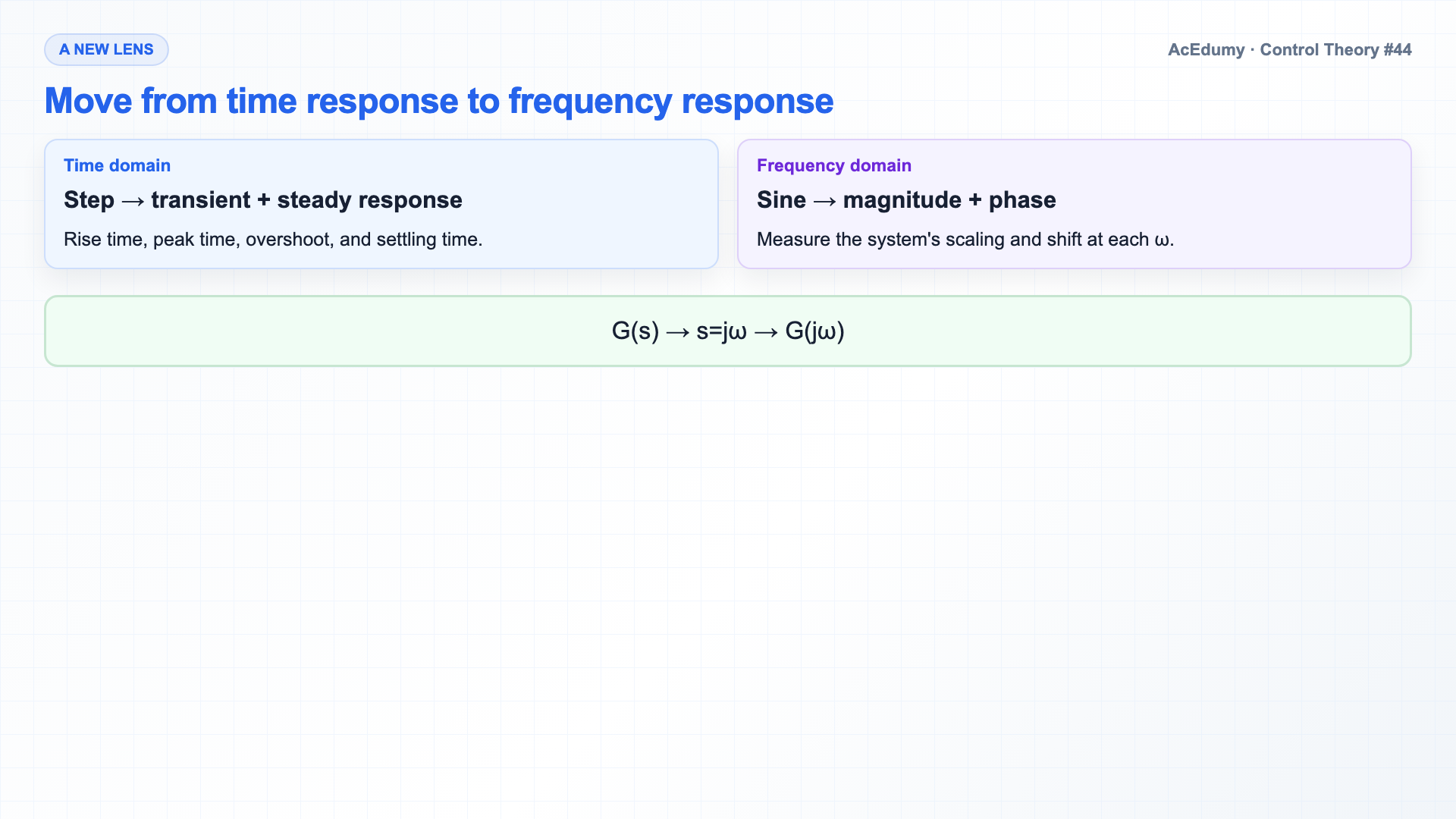
For a stable LTI system, a unit sinusoid is scaled by |G(jω)| and shifted by ∠G(jω); use atan2 for the general phase. Quick recap.So far we have studied a system through its time response — step input, step output, settling time, overshoot.Today we change the lens.Instead of a step, we send in a pure sine wave, and ask what comes out.The answer is the frequency response — and it is the most powerful tool in classical control.Narration transcript
Quick recap. So far we have studied a system through its time response — step input, step output, settling time, overshoot. Today we change the lens. Instead of a step, we send in a pure sine wave, and ask what comes out. The answer is the frequency response — and it is the most powerful tool in classical control.
2. Explain the three roles of sinusoids
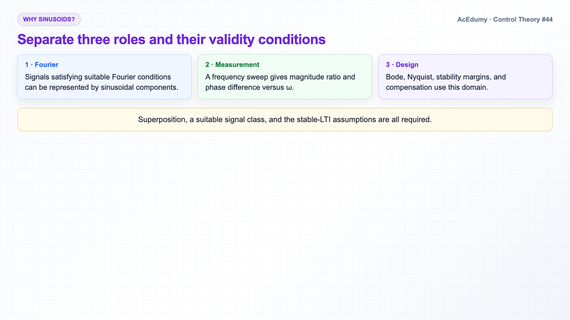
For a stable LTI system, a unit sinusoid is scaled by |G(jω)| and shifted by ∠G(jω); use atan2 for the general phase. Why care about sine waves?Three reasons.First — signals satisfying suitable Fourier conditions can be represented by sinusoidal components.That is the Fourier idea.For a suitable signal class, the component responses can be combined by superposition.Second — frequency response is what we measure in the lab.Drive a sweep into the system, plot magnitude and phase versus frequency.The curve we get is the system, in a different language.Third — every classical design tool from here on — Bode plots, Nyquist stability, gain and phase margins, lead-lag compensators, PID tuning — lives in frequency space.Master the frequency response, and the rest is geometry.Narration transcript
Why care about sine waves? Three reasons. First — every real signal can be written as a sum of sinusoids. That is the Fourier idea. If we know how the system handles each individual sine, we know how it handles every signal. Second — frequency response is what we measure in the lab. Drive a sweep into the system, plot magnitude and phase versus frequency. The curve we get is the system, in a different language. Third — every classical design tool from here on — Bode plots, Nyquist stability, gain and phase margins, lead-lag compensators, PID tuning — lives in frequency space. Master the frequency response, and the rest is geometry.
3. Establish the sinusoidal eigenfunction result for a stable LTI system
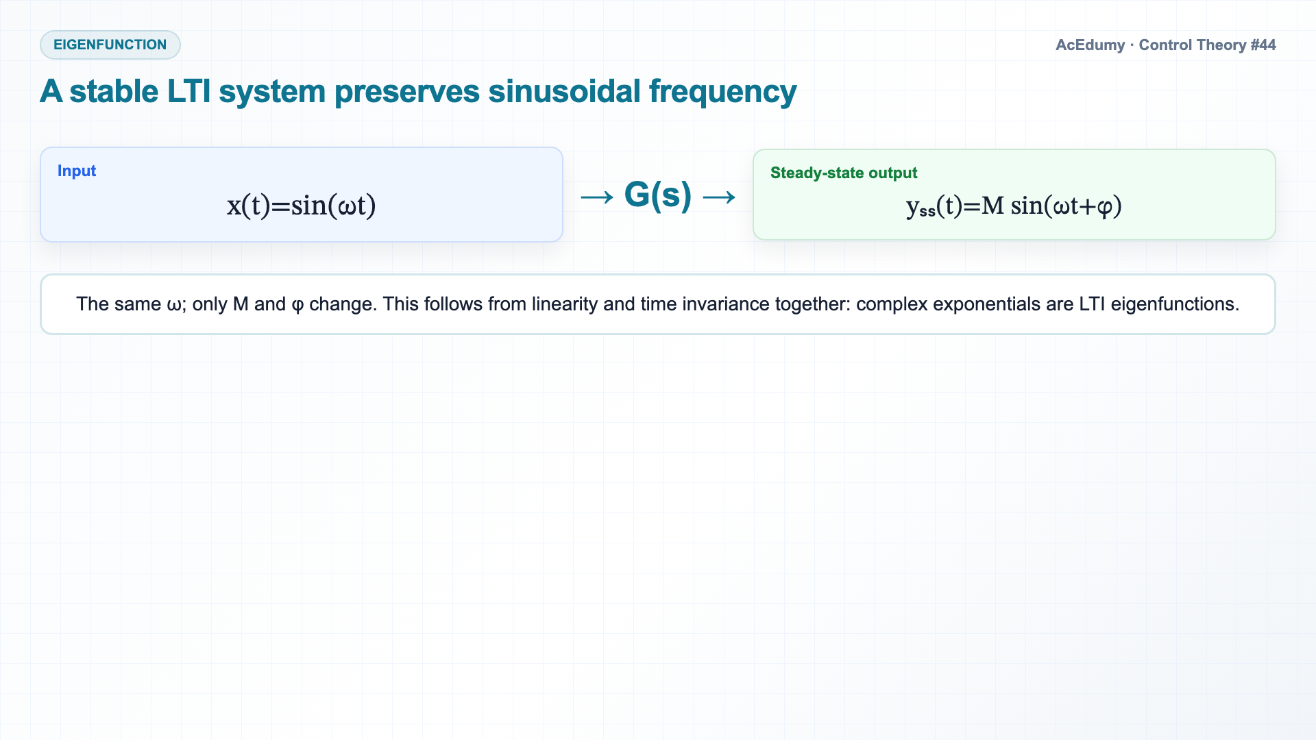
For a stable LTI system, a unit sinusoid is scaled by |G(jω)| and shifted by ∠G(jω); use atan2 for the general phase. The thought experiment.Imagine an LTI system, a black box.Input — a pure sine wave, sin omega t.Wait for transients to die out — that is the steady state.What does the output look like?It turns out the output is also a pure sine wave at the same frequency omega.In steady state, complex exponentials are eigenfunctions of an LTI system; preserving frequency requires linearity and time invariance together.But two things are different.The amplitude is scaled by a factor.And the phase is shifted by an angle.Both depend on omega.Send in a slow sine, you get one amplitude and one phase.Send in a fast sine, you get a different amplitude, a different phase.The system speaks a different dialect at every frequency.Narration transcript
The thought experiment. Imagine an LTI system, a black box. Input — a pure sine wave, sin omega t. Wait for transients to die out — that is the steady state. What does the output look like? It turns out the output is also a pure sine wave at the same frequency omega. The system cannot create new frequencies — that is the linearity promise. But two things are different. The amplitude is scaled by a factor. And the phase is shifted by an angle. Both depend on omega. Send in a slow sine, you get one amplitude and one phase. Send in a fast sine, you get a different amplitude, a different phase. The system speaks a different dialect at every frequency.
4. Write the steady-state magnitude and phase formula
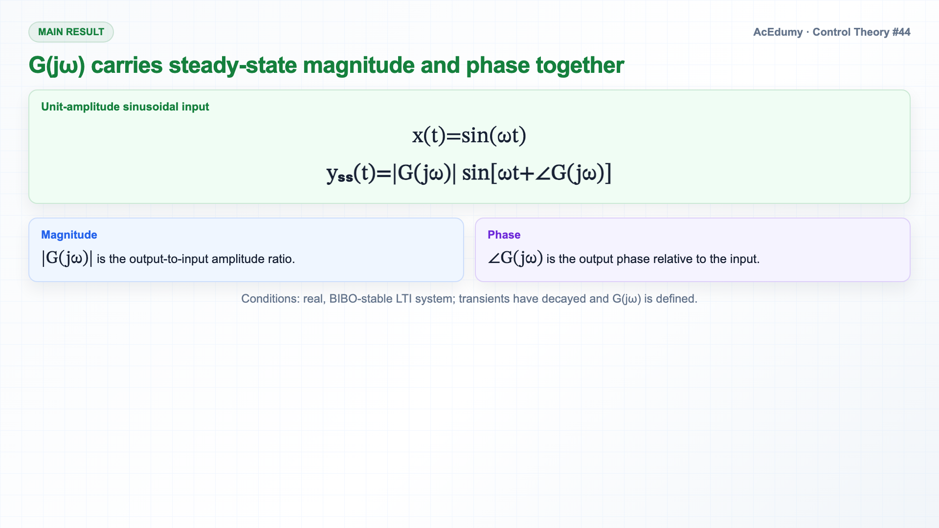
For a stable LTI system, a unit sinusoid is scaled by |G(jω)| and shifted by ∠G(jω); use atan2 for the general phase. The main result, in one line.For the unit input x(t)=sin(ωt), yₛₛ(t)=|G(jω)|sin[ωt+∠G(jω)].That is the entire story.Two numbers — magnitude and phase — at each frequency.Where does the formula come from?A two-step argument.Take the Laplace transform of sin omega t, multiply by G of s, do partial fractions.In a BIBO-stable LTI system the transient terms decay; assume G(jω) is defined.What survives are the two terms with poles at plus and minus j omega — and those combine into a sinusoid with amplitude the magnitude of G of j omega and phase the angle of G of j omega.We do not need the full derivation today.For a suitable transfer function, compute the frequency response by substituting s=jω.The complex number you get encodes both the magnitude scaling and the phase shift.Narration transcript
The main result, in one line. For input sin omega t into an LTI system G of s, the steady-state output is the magnitude of G of j omega, times sin of omega t plus the angle of G of j omega. That is the entire story. Two numbers — magnitude and phase — at each frequency. Where does the formula come from? A two-step argument. Take the Laplace transform of sin omega t, multiply by G of s, do partial fractions. The transient pieces decay because the system is stable. What survives are the two terms with poles at plus and minus j omega — and those combine into a sinusoid with amplitude the magnitude of G of j omega and phase the angle of G of j omega. We do not need the full derivation today. The takeaway — to find the frequency response, just substitute s equals j omega into your transfer function. The complex number you get encodes both the magnitude scaling and the phase shift.
5. Compute magnitude and phase from G(jω) correctly
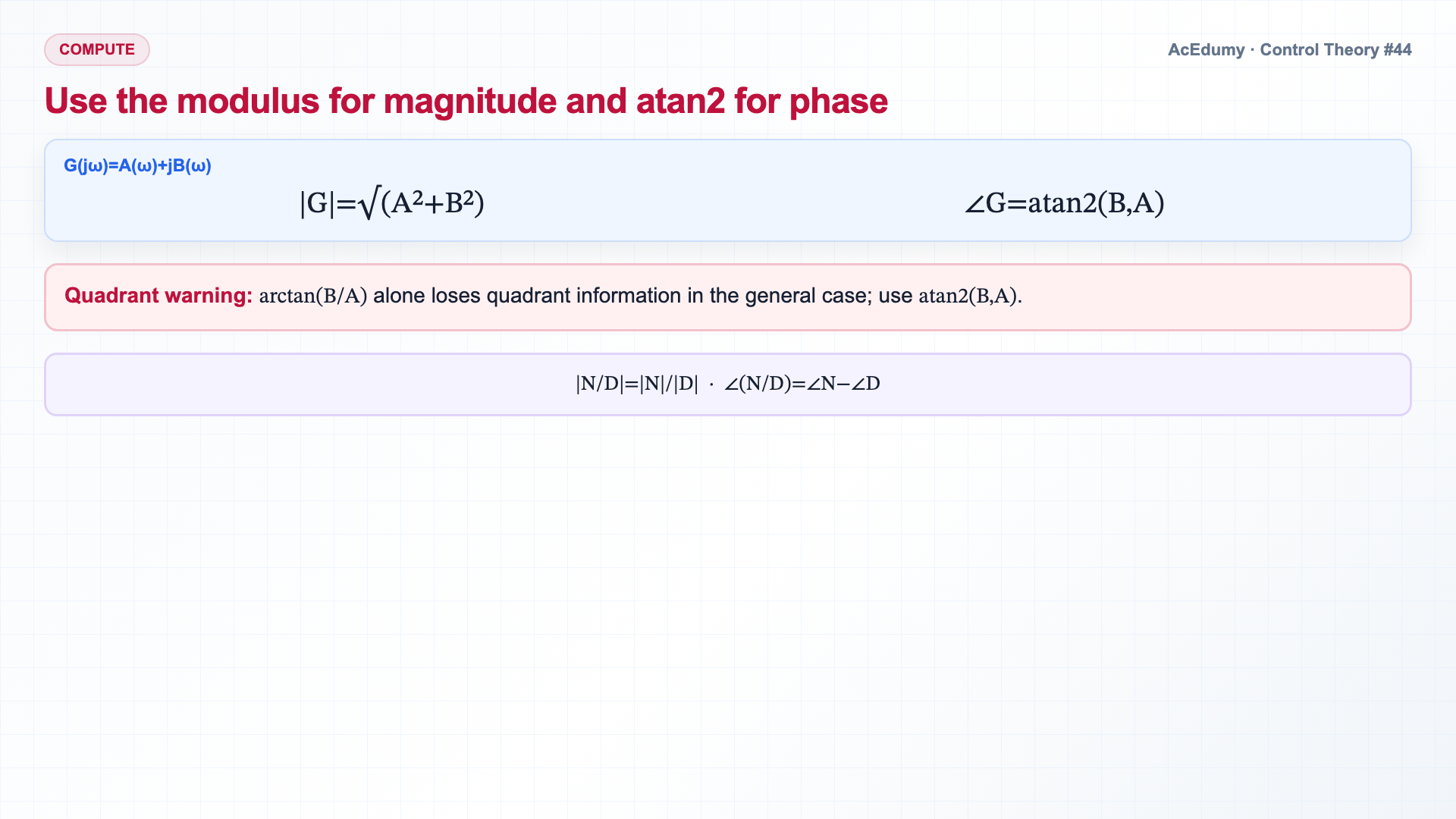
For a stable LTI system, a unit sinusoid is scaled by |G(jω)| and shifted by ∠G(jω); use atan2 for the general phase. How to compute G of j omega.Substitute s equals j omega into G of s.Now you have a complex-valued function of the real variable omega.From that complex number, extract two real numbers.Magnitude — the modulus of G of j omega, written as the absolute value of G of j omega.This is the gain at frequency omega.Phase — the argument of G of j omega, written as angle G of j omega.This is the phase shift the system imposes at frequency omega.If G(jω)=A+jB, then |G|=√(A²+B²) and the general phase is ∠G=atan2(B,A); the source audio's arctan(B/A) rule loses quadrant information.Most transfer functions are rational — a polynomial over a polynomial.For those, factor the numerator and denominator, then magnitude is product of factor magnitudes divided by product of factor magnitudes, and phase is sum of factor phases minus sum of factor phases.Each factor is easy to handle by itself.Narration transcript
How to compute G of j omega. Substitute s equals j omega into G of s. Now you have a complex-valued function of the real variable omega. From that complex number, extract two real numbers. Magnitude — the modulus of G of j omega, written as the absolute value of G of j omega. This is the gain at frequency omega. Phase — the argument of G of j omega, written as angle G of j omega. This is the phase shift the system imposes at frequency omega. If G of j omega equals A plus j B, then magnitude equals root A squared plus B squared, and phase equals arctan B over A. Most transfer functions are rational — a polynomial over a polynomial. For those, factor the numerator and denominator, then magnitude is product of factor magnitudes divided by product of factor magnitudes, and phase is sum of factor phases minus sum of factor phases. Each factor is easy to handle by itself.
6. Solve the frequency response of 1/(s+1)
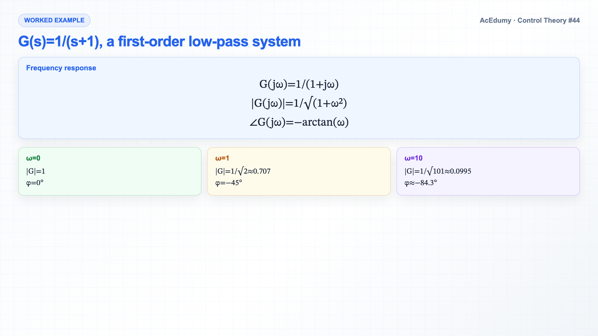
For a stable LTI system, a unit sinusoid is scaled by |G(jω)| and shifted by ∠G(jω); use atan2 for the general phase. Worked example.Take G(s)=1/(s+1).A simple first-order low-pass filter.Substitute s=jω to obtain G(jω)=1/(1+jω).To find the magnitude, multiply numerator and denominator by the complex conjugate, or use the rule directly.For the phase, the angle of one is zero, and the angle of j omega plus one is arctan omega over one, equal to arctan omega.Here 1+jω lies in the first quadrant, so ∠G(jω)=−arctan(ω).Plug in some numbers.At ω=0 (DC), |G|=1 and phase is 0°.The system passes DC perfectly.At ω=1, |G|=1/√2≈0.707 and phase is −45°.At ω=10, |G|=1/√101≈0.0995 and phase is approximately −84.3°; it approaches −90° only as ω→∞.The system attenuates and delays high frequencies.That is the signature of a low-pass filter.Narration transcript
Worked example. Take G of s equals one over s plus one. A simple first-order low-pass filter. Substitute s equals j omega — get G of j omega equals one over j omega plus one. To find the magnitude, multiply numerator and denominator by the complex conjugate, or use the rule directly. The magnitude of one over j omega plus one is one over the magnitude of j omega plus one, which is one over root one plus omega squared. For the phase, the angle of one is zero, and the angle of j omega plus one is arctan omega over one, equal to arctan omega. So angle of G of j omega is zero minus arctan omega, which is just minus arctan omega. Plug in some numbers. At omega equals zero — DC — magnitude is one, phase is zero. The system passes DC perfectly. At omega equals one — the corner frequency — magnitude is one over root two, which is approximately 0.707, and phase is minus 45 degrees. At omega equals 10 — well above the corner — magnitude is about 0.1, and phase approaches minus 90 degrees. The system attenuates and delays high frequencies. That is the signature of a low-pass filter.
7. Convert magnitude to decibels and scope the cutoff interpretation
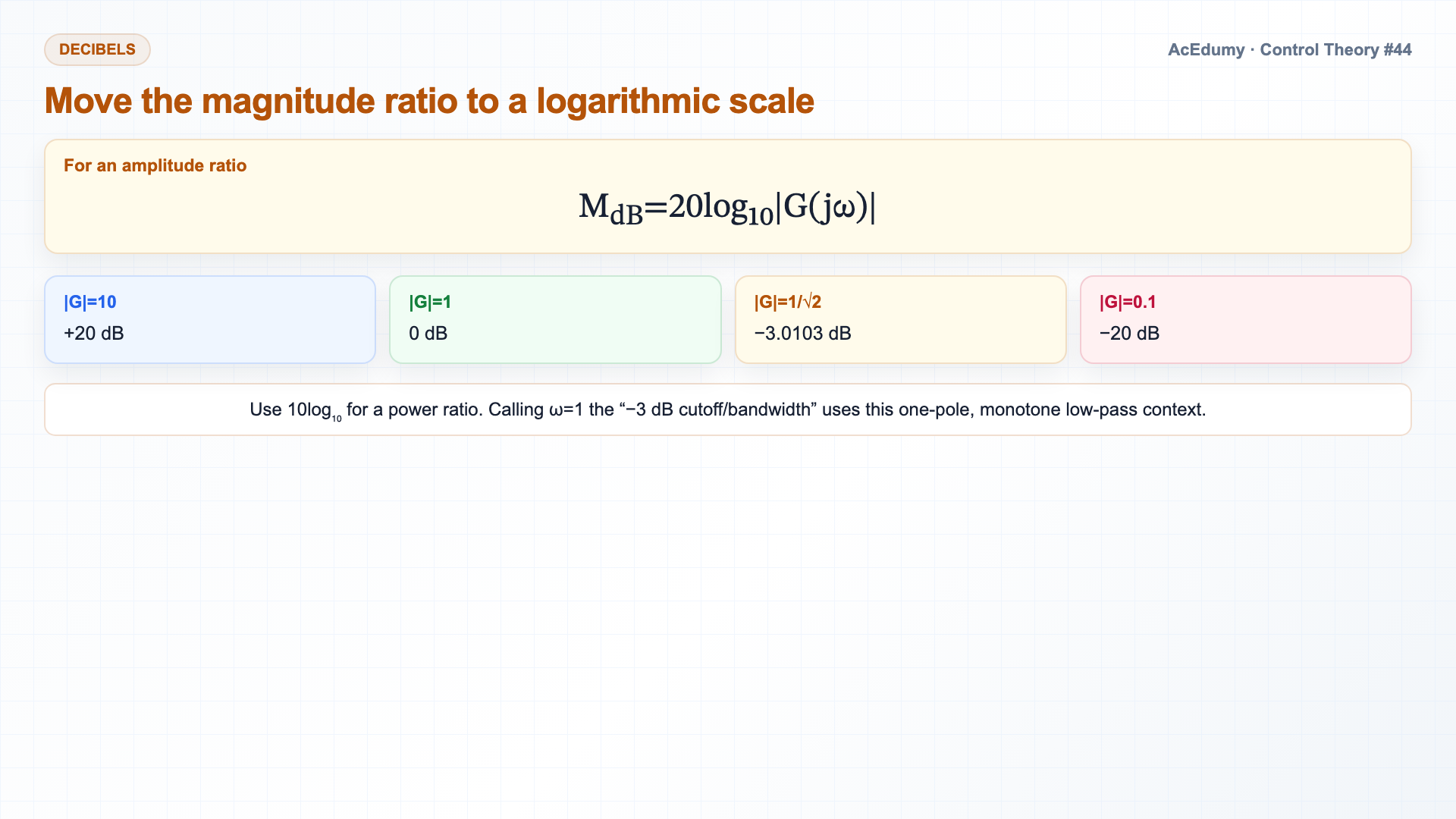
For a stable LTI system, a unit sinusoid is scaled by |G(jω)| and shifted by ∠G(jω); use atan2 for the general phase. One last piece — decibels.Frequency response magnitudes span many orders of magnitude.To compress the range and turn products into sums, we use a logarithmic scale.For an amplitude ratio, MdB=20log₁₀|G(jω)|; use 10log₁₀ for a power ratio.A magnitude of 1 is 0 dB.A magnitude of 10 is 20 dB.A magnitude of 0.1 is minus 20 dB.|G|=1/√2 is −3.0103 dB; in this one-pole low-pass example the DC-relative −3 dB point is both its cutoff and bandwidth.From now on, when we plot magnitude, we will plot it in dB on a log-frequency axis.That is the Bode plot — coming up next.Narration transcript
One last piece — decibels. Frequency response magnitudes span many orders of magnitude. To compress the range and turn products into sums, we use a logarithmic scale. Magnitude in decibels equals 20 times log base 10 of the magnitude. A magnitude of 1 is 0 dB. A magnitude of 10 is 20 dB. A magnitude of 0.1 is minus 20 dB. A magnitude of one over root two is about minus 3 dB — and that minus 3 dB number is so famous it has its own name, the minus 3 dB cutoff frequency, the bandwidth. From now on, when we plot magnitude, we will plot it in dB on a log-frequency axis. That is the Bode plot — coming up next.
8. Interpret the frequency-response curves together
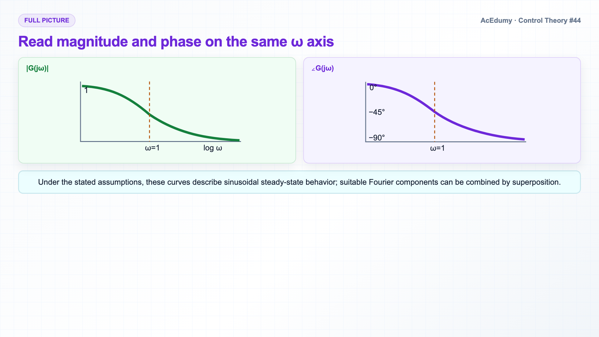
For a stable LTI system, a unit sinusoid is scaled by |G(jω)| and shifted by ∠G(jω); use atan2 for the general phase. The full picture.The frequency response is not just one number — it is a function of omega.For each omega from zero to infinity, we get a magnitude and a phase.Plot both, and you have the complete fingerprint of the system.For our example G equals one over s plus one — magnitude starts at 1 at DC, drops to 0.707 at the corner, falls off as one over omega for high frequencies.Phase starts at 0, passes minus 45 degrees at the corner, approaches minus 90 degrees as omega goes to infinity.Under the stated assumptions, these two curves describe the system's sinusoidal steady-state behavior.They give the sinusoidal response directly; responses of suitable Fourier components can be combined by superposition.Narration transcript
The full picture. The frequency response is not just one number — it is a function of omega. For each omega from zero to infinity, we get a magnitude and a phase. Plot both, and you have the complete fingerprint of the system. For our example G equals one over s plus one — magnitude starts at 1 at DC, drops to 0.707 at the corner, falls off as one over omega for high frequencies. Phase starts at 0, passes minus 45 degrees at the corner, approaches minus 90 degrees as omega goes to infinity. These two curves are the system. They contain everything you need to predict how the system will respond to any sinusoidal input — and by Fourier, to any input.
9. Summarize the frequency-response results
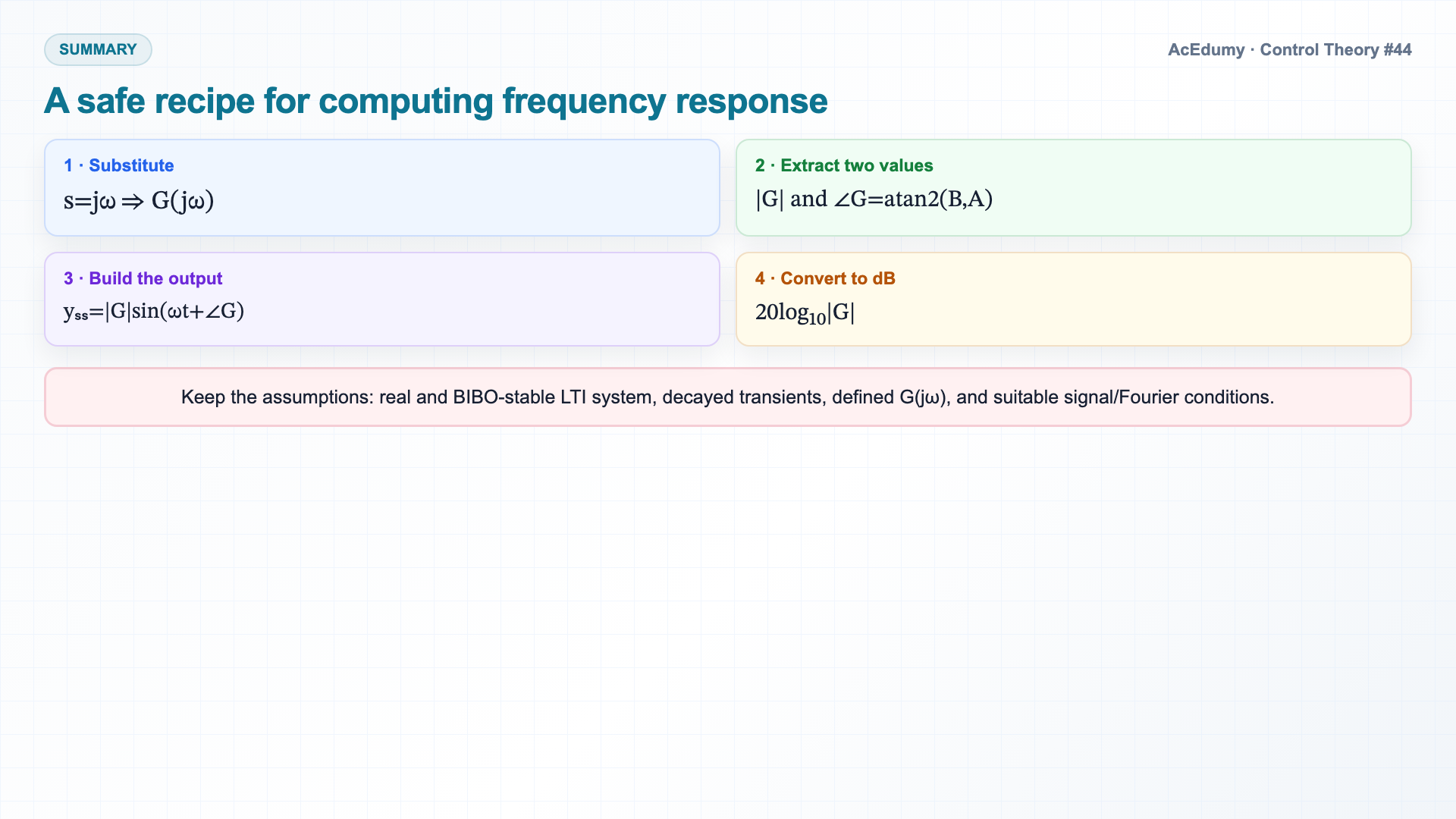
For a stable LTI system, a unit sinusoid is scaled by |G(jω)| and shifted by ∠G(jω); use atan2 for the general phase. Summary.Send a sinusoid into a stable LTI system, wait for transients to die, the output is a sinusoid at the same frequency, with amplitude scaled by the magnitude of G of j omega and phase shifted by the angle of G of j omega.To compute, substitute s equals j omega into G of s.Magnitude and phase fall out of the resulting complex number.Magnitudes are usually plotted in decibels.For an amplitude ratio, dB=20log₁₀|G(jω)|.Magnitude and phase versus frequency describe a stable LTI system's sinusoidal steady-state behavior under suitable regularity conditions.Every classical design tool from here lives in this space.Next — we learn to draw it efficiently, the Bode plot.Narration transcript
Summary. Send a sinusoid into a stable LTI system, wait for transients to die, the output is a sinusoid at the same frequency, with amplitude scaled by the magnitude of G of j omega and phase shifted by the angle of G of j omega. To compute, substitute s equals j omega into G of s. Magnitude and phase fall out of the resulting complex number. Magnitudes are usually plotted in decibels. dB equals 20 log magnitude. The frequency response — magnitude and phase versus frequency — is a complete description of an LTI system. Every classical design tool from here lives in this space. Next — we learn to draw it efficiently, the Bode plot.
Source video: Control Theory #44 — Sinusoidal Steady-State and Frequency Response (Lecture 5 · Part 1) (8:47)