Circuit Theory 1 · Thevenin and Norton
#27 Thevenin and Norton #27 — 1 V test source and a second dependent-source example
Uses a 1 V test source and a short circuit to find the Thevenin resistance of two dependent-source circuits.
Question
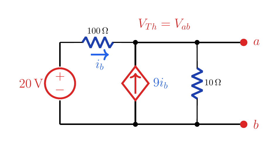
Verify R_Th in the first circuit with a 1 V test source. For the second circuit, find V_Th, I_sc, R_Th, and the Norton equivalent seen by load R_3.
Written solution and narration transcript(shows the full solution)
Below are all the lines written in the notebook together with the full narration transcript.
1. Example 1 recap
V_Th=10 V is already known; R_Th will now be found with a 1 V test source. Example 1: where we left offDependent source: 9ibEarlier methods: Isc and 1 ANew method: 1 V test voltageTurn off the 20 V sourceKeep the dependent sourceNarration transcript
In the previous lesson we found the Thevenin equivalent of this dependent-source circuit using short-circuit current and a one amp test source. Here we keep the same circuit, but use the third resistance method: add a one volt test voltage source at terminals a and b.
2. 1 V test source
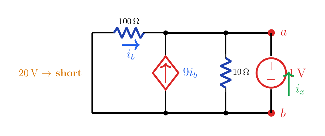
i_b=−0.01 A and i_x=0.2 A, so R_Th=5 Ω. 1 V test source20 V → short circuitVab=1 V (+ at a)Test current: ixNarration transcript
First, the open-circuit voltage is still V Thevenin equal to 10 volts. To find R Thevenin with the voltage-source method, turn off the independent 20 volt source, so it becomes a short circuit. Then connect a 1 volt source from b to a, with the positive terminal at a.
3. Test-voltage result
i_b=−0.01 A and i_x=0.2 A, so R_Th=5 Ω. Test-voltage resultNarration transcript
The terminal node is now at 1 volt. The control current is i b equals zero minus one over 100, so i b is negative 0.01 ampere. KCL at the top node gives 10 i b plus i x equals one over 10. Substituting i b gives i x equal to 0.2 ampere. Therefore R Thevenin is one volt divided by 0.2 ampere, or 5 ohms.
4. Example 2
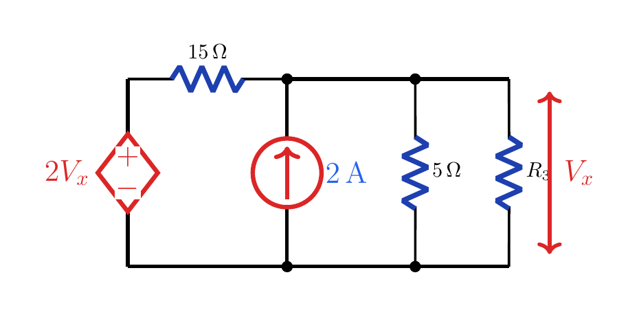
V_x is the voltage of node a relative to b and the load voltage across R_3. Example 2: dependent voltage sourceLoad: R3Controlling voltage:Dependent source: 2VxResistors: 15 Ω and 5 ΩIndependent source: 2 ARequired: VTh and RThNarration transcript
Now use a second example. We want the Thevenin equivalent seen by the load resistor R 3. The circuit has a dependent voltage source of value 2 V x, a 15 ohm resistor, a 2 amp current source, and a 5 ohm branch. The voltage V x is the terminal voltage across R 3, from a to b.
5. Open circuit
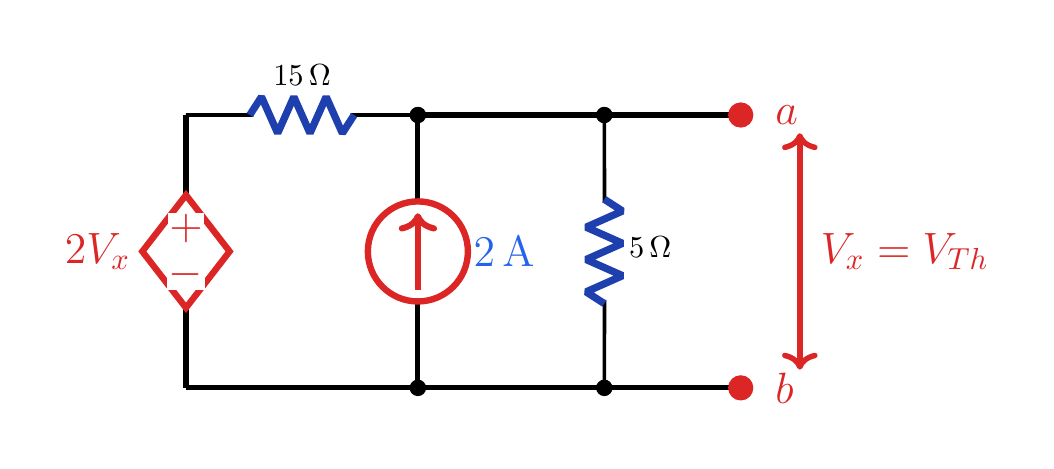
The node equation gives V_x=V_Th=15 V. Open-circuit voltageRemove R3Narration transcript
Remove the load R 3 and find the open-circuit voltage. Since V x is the same as the terminal voltage, write KCL at the top node: V x minus 2 V x over 15, plus V x over 5, minus 2 equals zero. This simplifies to 2 V x over 15 equals 2, so V x equals 15 volts. Thus V Thevenin is 15 volts.
6. Short circuit
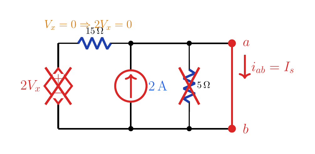
The full 2 A source current becomes the short-circuit current from a to b. Short-circuit methodShort terminals a-b2Vx=0 V → wireNo current in the 5 Ω branchCurrent direction: a→bNarration transcript
For the short-wire method, short terminals a and b. The terminal voltage V x becomes zero. That makes the dependent voltage source 2 V x equal to zero volts, so it acts like a short circuit, and the 5 ohm branch also has zero volts. The 2 amp current source now sends 2 amperes through the short.
7. Equivalent circuit
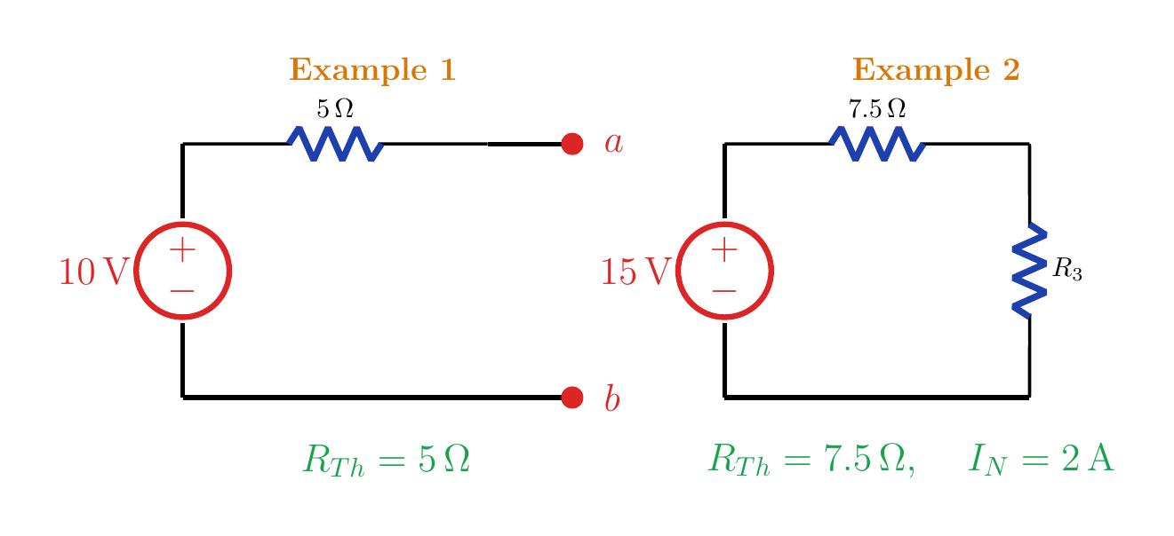
The Norton equivalent of example 2 is 2 A in parallel with 7.5 Ω. Example 2 equivalentThevenin: 15 V in series with 7.5 ΩNorton: 2 A in parallel with 7.5 ΩNarration transcript
The short-circuit current is 2 amperes. Therefore R Thevenin is V Thevenin divided by I short, equal to 15 volts divided by 2 amperes. The result is 7.5 ohms. The Thevenin model is a 15 volt source in series with 7.5 ohms, feeding the load R 3.
8. Method summary
The Norton equivalent of example 2 is 2 A in parallel with 7.5 Ω. Method summaryTurn off independent sourcesKeep dependent sources activeTest voltage:Test current:Short circuit:All three methods give the same RThNarration transcript
The pattern is now complete. With dependent sources, do not turn off the dependent source by itself. For a test source, turn off only the independent sources and keep the controlling variable in the equations. For a short-circuit method, use V Thevenin divided by I short. Both approaches give the same resistance when the signs are tracked consistently.
Source video: Circuit Theory #27 | Thevenin with a Test Voltage Source - Dependent Source Example (3:22)